Subaru Impreza 3 / Impreza WRX / Impreza WRX STI. Manual - part 26


  Index      Subaru     Subaru Impreza 3 / Impreza WRX / Impreza WRX STI - service repair manual 2008-2014 year


Search            


Content   ..  24  25  26  27   ..


Subaru Impreza 3 / Impreza WRX / Impreza WRX STI. Manual - part 26


FU(STI)-16

Throttle Body

FUEL INJECTION (FUEL SYSTEMS)

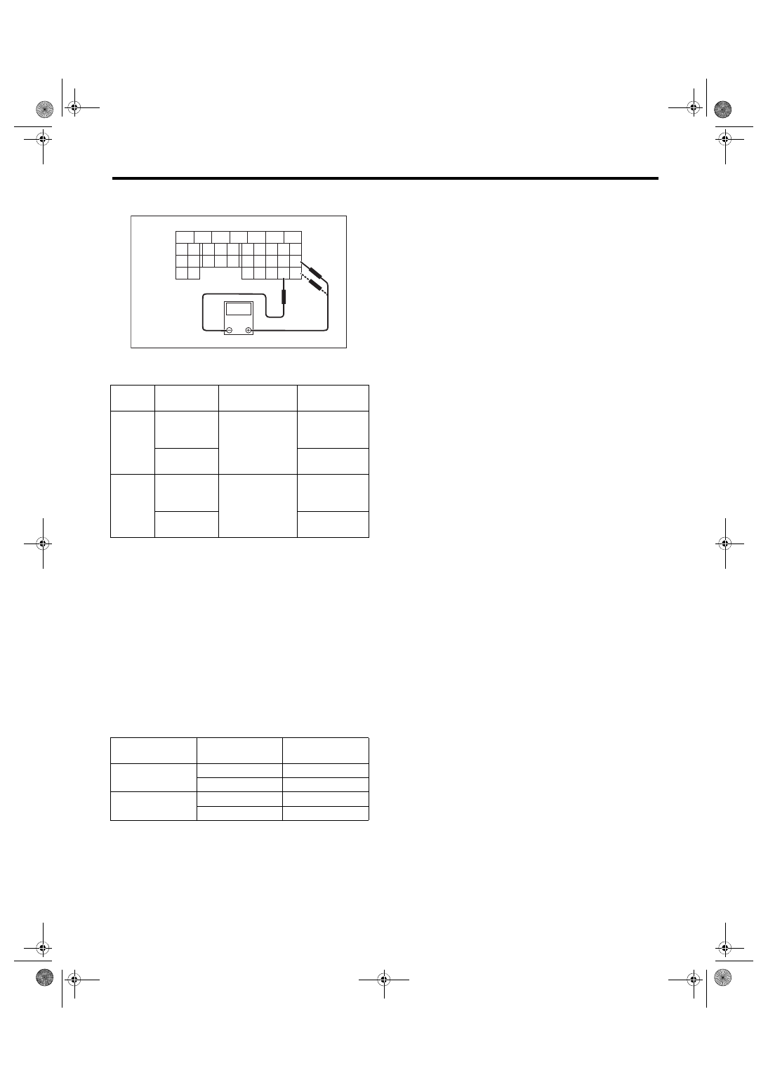
6) Measure  the  voltage  between  ECM  connector

terminals.

7) After  inspection,  install  the  related  parts  in  the

reverse order of removal.
Tightening torque:

7.5 N·m (0.8 kgf-m, 5.5 ft-lb)

2. THROTTLE SENSOR INSPECTION 

(METHOD WITH SUBARU SELECT MONI-

TOR)

1) Turn the ignition switch to ON. (engine OFF)

2) Read the throttle opening angle signal and volt-

age of throttle sensor using Subaru Select Monitor.

<Ref. to EN(H4DOTC)(diag)-41, READ CURRENT

DATA FOR ENGINE (NORMAL MODE), OPERA-

TION, Subaru Select Monitor.>

3. OTHER INSPECTIONS

1) Check that the throttle body has no deformation,

cracks or other damages.

2) Check  that  the  engine  coolant  hose  has  no

cracks, damage or loose part.

(A) To ECM connector

Throttle 

sensor

Accelerator 

pedal

Terminal No.

Standard

Main

Not 
depressed 
(Full closed)

18 (+) and 29 (–)

Approx. 0.6 V

Depressed 
(Full opened)

Approx. 3.96 V

Sub

Not 
depressed 
(Full closed)

28 (+) and 29 (–)

Approx. 1.48 V

Depressed 
(Full opened)

Approx. 4.17 V

Throttle sensor

Throttle opening 

angle signal

Standard

Main

0.0%

Approx. 0.6 V

100.0%

Approx. 3.96 V

Sub

0.0%

Approx. 1.48 V

100.0%

Approx. 4.17 V

FU-04049

5

6

7

8

2

1

9

4

3

10

24

22

23

25

11

12

13

14

15

26

27

28

16

17

18

19

20

21

33

34

29

32

30

31

V

(A)

FU(STI)-17

Intake Manifold

FUEL INJECTION (FUEL SYSTEMS)

3. Intake Manifold

A: REMOVAL

1) Remove the V-belt covers.

2) Collect the refrigerant from A/C system. <Ref. to

AC-19, PROCEDURE, Refrigerant Recovery Pro-

cedure.>

3) Release the fuel pressure. <Ref. to FU(STI)-67,

RELEASING  OF  FUEL  PRESSURE,  PROCE-

DURE, Fuel.>

4) Disconnect the ground cable from battery.

5) Open the fuel filler lid and remove the fuel filler

cap.

6) Lift up the vehicle.

7) Remove  the  under  cover.  <Ref.  to  EI-28,  RE-

MOVAL, Front Under Cover.>

8) Drain approximately 3.0 L (3.2 US qt, 2.6 Imp qt)

of  coolant.  <Ref.  to  CO(STI)-13,  DRAINING  OF

ENGINE  COOLANT,  REPLACEMENT,  Engine

Coolant.>

9) Remove the air intake duct. <Ref. to IN(STI)-10,

REMOVAL, Air Intake Duct.>

10) Remove the air intake boot.

11) Remove  the  intercooler.  <Ref.  to  IN(STI)-12,

REMOVAL, Intercooler.>

12) Remove  the  generator.  <Ref.  to  SC(STI)-21,

REMOVAL, Generator.>

13) Remove  the  coolant  filler  tank.  <Ref.  to

CO(STI)-28, REMOVAL, Coolant Filler Tank.>

14) Disconnect  the A/C pressure hoses from  A/C

compressor. <Ref. to AC-41, REMOVAL, Hose and

Pipe.>

15) Disconnect the engine coolant hose from throt-

tle body.

16) Disconnect the brake booster vacuum hose (A)

and pressure regulator vacuum hose (B) from the

intake manifold.

17) Disconnect the connector from the PCV hose

assembly A.

FU-03487

IN-00203

LU-02413

FU-05761

ME-05007

E N G

(A)

(B)

FU-06567

FU(STI)-18

Intake Manifold

FUEL INJECTION (FUEL SYSTEMS)

18) Remove  the  PCV  hose  assembly  A  from  clip

(A), and remove the vacuum hose from clip (B).

19) Disconnect the vacuum hose (A) and the con-

nector (B) from the PCV hose assembly B.

20) Disconnect  the  air  control  hose  (A)  from  the

waste gate actuator, and loosen the clamp which

holds the intake duct to the turbocharger.

21) Remove the engine coolant hose from the wa-

ter tank pipe.

22) Remove the engine harness from clip (A).

23) Disconnect  the  bulkhead  harness  connectors

from the engine harness connectors.

24) Remove  the  engine  harness  connector  from

the engine harness bracket.

25) Disconnect the connector (A) from the engine

coolant temperature sensor, connector (B) from the

oil  pressure  switch,  and  connector  (C)  from  the

crankshaft position sensor.

FU-06568

(A)

(B)

(A)

(B)

FU-06566

FU-04384

(A)

FU-06569

FU-06570

(A)

FU-06571

FU-06572

(C)

(A)

(B)

FU-05725

FU(STI)-19

Intake Manifold

FUEL INJECTION (FUEL SYSTEMS)

26) Disconnect the connector from power steering

pump switch.

27) Disconnect the connector from the knock sen-

sor.

28) Disconnect the connector from the secondary

air combination valve.

29) Disconnect the connector from the intake cam-

shaft position sensor.

30) Disconnect  the  connector  from  the  intake  oil

flow control solenoid valve.

31) Lift up the vehicle.

FU-04598

FU-03492

FU-03493

FU-04385

FU-03495


Content   ..  24  25  26  27   ..