Subaru Impreza 3 / Impreza WRX / Impreza WRX STI. Manual - part 24


  Index      Subaru     Subaru Impreza 3 / Impreza WRX / Impreza WRX STI - service repair manual 2008-2014 year


Search            


Content   ..  22  23  24  25   ..


Subaru Impreza 3 / Impreza WRX / Impreza WRX STI. Manual - part 24


PM-34

Steering System (Power Steering)

PERIODIC MAINTENANCE SERVICES

24.Steering System (Power 

Steering)

A: INSPECTION

1. STEERING WHEEL

1) Set the steering wheel in a straight-ahead posi-

tion,  and  check  the  wheel  spokes  to  make  sure

they are correctly set in their specified positions.

2) Lightly  turn  the  steering  wheel  to  the  left  and

right to determine the point where front wheels start

to move.

Measure the distance of the movement of steering

wheel at the outer periphery of wheel.
Steering wheel free play:

0 — 17 mm (0 — 0.67 in)

Move the steering wheel vertically toward the shaft

to ascertain if there is play in the direction.
Maximum permissible play:

0.5 mm (0.020 in)

3) Drive the vehicle and check the following items

during operation.

(1) Steering force:

The  effort  required  for  steering  should  be

smooth and even at all points, and should not

vary.

(2) Pulled to one side:

Steering  wheel  should  not  be  pulled  to  either

side while driving on a level surface.

(3) Wheel runout:

Steering  wheel  should  not  show  any  sign  of

runout.

(4) Return factor:

Steering wheel should return to its original posi-

tion after it has been turned and then released.

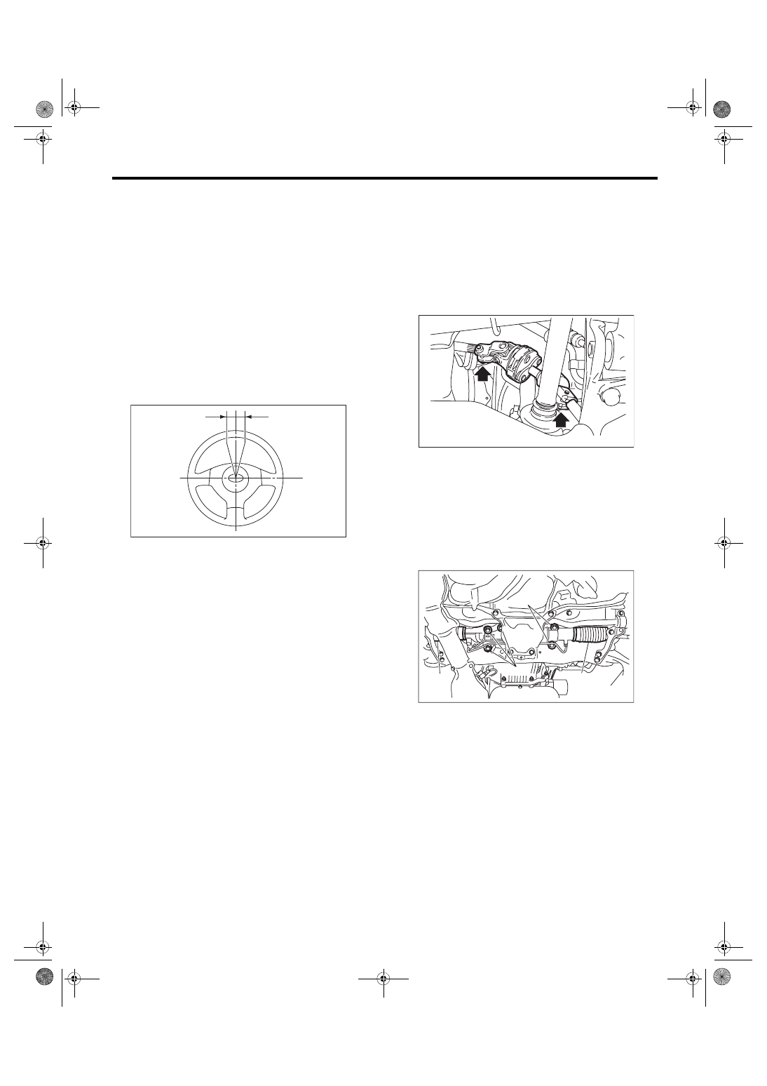
2. STEERING SHAFT JOINT

If steering wheel play is excessive, disconnect the

universal joint of steering shaft and then check the

play where the joints cross and yawing torque. Al-

so,  check  the  seal  for  damage  or  serrations  for

wear. If loose joints, tighten the mounting bolts to

specified torque.
Tightening torque:

24 N·m (2.4 kgf-m, 17.7 ft-lb)

3. GEARBOX

1) With the vehicle placed on a level surface, turn

the steering wheel 90° in both the left and right di-

rections.

While the wheel is being rotated, reach under the

vehicle and check for looseness in gearbox.
Tightening torque:

60 N·m (6.1 kgf-m, 44.3 ft-lb)

2) Check the boot for damage, cracks or deteriora-

tion.

(1) Steering wheel free play

(1)

PS-00450

(A) Boot
(B) Gearbox mounting bolt

PM-00392

PM-00393

(A)

(A)

(B)

(B)

gi14usena07.fm  34 ページ  2013年9月10日 火曜日 午後3時59分

PM-35

Steering System (Power Steering)

PERIODIC MAINTENANCE SERVICES

3) With the vehicle placed on a level surface, quick-

ly turn the steering wheel to the left and right.

While  steering  wheel  is  being  rotated,  check  the

gear  backlash.  If  any  noise  is  noticed,  adjust  the

gear backlash in the following manner.

(1) Loosen the adjusting screw, and apply liquid

gasket to at least 1/3 of the entire perimeter of

adjusting screw thread.

Liquid gasket:

THREE BOND 1102 or 1215

(2) Tighten the adjusting screw, then loosen it.

CAUTION:

Adjust the steering rack to the straight forward

position.
Tightening torque:

25 N·m (2.5 kgf-m, 18 ft-lb)

(3) Tighten the adjusting screw, then loosen it.

(4) Tighten the adjusting screw.

Tightening torque:

5.9 N·m (0.6 kgf-m, 4.2 ft-lb)

(5) Then, return the adjusting screw by 20° and

fix it.

(6) Install the lock nut. While holding the adjust-

ing screw with wrench, tighten the lock nut us-

ing ST.

ST 926230000

SPANNER

Tightening torque (lock nut):

25 N·m (2.5 kgf-m, 18 ft-lb)

Hold the adjusting screw with wrench to prevent

it from turning while tightening the lock nut.

4. TIE-ROD

1) Check  the  tie-rod  and  tie-rod  end  for  bend,

cracks or other damages.

2) Make sure there is free play at the connection of

knuckle ball joint and check the dust seal for dam-

age, and the ball stud for play. If loose castle nut,

tighten  it  to  the  specified  tightening  torque,  and

tighten further within 60° until the cotter pin hole is

aligned.
Tightening torque:

27 N·m (2.75 kgf-m, 19.9 ft-lb)

3) Check the tightening of tie-rod end lock nut. If it

is loose, tighten it to the specified torque.
Tightening torque:

85 N·m (8.7 kgf-m, 62.7 ft-lb)

5. POWER STEERING FLUID LEVEL

NOTE:

• At power steering fluid temperature 20°C (68°F);

read the fluid level on the “COLD” side.

• At  power  steering  fluid  temperature  80°C

(176°F); read the fluid level on the “HOT” side.

1) Place the vehicle with engine “OFF” on a level

surface.

2) Check the fluid level using the scale on the out-

side of the reservoir tank (A). If the level is below

“MIN”, fill fluid up to “MAX” level.

(1) Apply liquid gasket to 1/3 or more of the entire 

perimeter.

PS-00092

(A) Tie-rod end
(B) Tie-rod

PM-00394

(A)

(B)

PI-00461

(A)

HOT  MAX

COLD  MAX

HOT  MIN

COLD  MIN

gi14usena07.fm  35 ページ  2013年9月10日 火曜日 午後3時59分

PM-36

Steering System (Power Steering)

PERIODIC MAINTENANCE SERVICES

CAUTION:

If the power steering fluid is spilt over exhaust

pipe,  wipe  it  off  with  cloth  to  avoid  emitting

smoke or causing a fire.
NOTE:

If fluid level is at MAX level or above, drain fluid to

keep the level in the specified range of indicator by

using a syringe or the like.
Recommended fluid:

Refer to “RM” section. <Ref. to RM-4, FLUID, 

RECOMMENDED MATERIALS, Recommend-

ed Materials.>

Fluid capacity:

0.7 L (0.7 US qt, 0.6 Imp qt)

6. POWER STEERING FLUID FOR LEAKS

Inspect the underside of oil pump and gearbox of

power steering system, hoses, pipes and their cou-

plings for fluid leaks.

If fluid leakage is found, tighten the mounting bolt

(or nut) again or replace with a new part.
NOTE:

• Wipe  the  leaked  fluid  off  after  correcting  fluid

leaks.

• When inspecting the fluid leakage, be careful of

the  clearance  between  the  hose  (or  piping)  and

other parts.

7. HOSES OF OIL PUMP FOR DAMAGES

Check  the  pressure  hose  and  return  hose  of  oil

pump for crack, swell or damage. Replace the hose

with a new part if necessary.
NOTE:

Prevent hoses from turning  and/or  bending  when

installing hoses.

8. POWER STEERING PIPES FOR DAMAG-

ES

Check the power steering pipes for corrosion and

damage.

Replace the pipe with a new part if necessary.

9. GEARBOX BOOTS

Inspect both sides of the gearbox boot as follows,

and correct the defects if necessary.

1) Positions (A) and (B) of the gearbox boot are fit-

ted correspondingly in grooves (A) and (B) of the

gearbox and rod (C).

2) Clips are fitted onto the boot grooves to the po-

sitions (A) and (B) of the boot.

3) Boot does not have crack or hole.
NOTE:

Rotate (B) position of gearbox boot against the tor-

sion produced by the adjustment of toe-in etc.

10.FITTING BOLTS AND NUTS

Inspect  the  fitting  bolts  and  nuts  of  oil  pump  and

bracket for looseness, and retighten them if neces-

sary.

Inspect and/or retighten them when engine is cold.

(1) Reservoir tank
(2) Suction hose
(3) Return hose
(4) Pressure hose

PM-00446

(3)

(1)

(2)

(4)

(C)

(B)

(A)

PM-00090

gi14usena07.fm  36 ページ  2013年9月10日 火曜日 午後3時59分

PM-37

A/C Filter

PERIODIC MAINTENANCE SERVICES

25.A/C Filter

A: REPLACEMENT

1) Remove the glove box damper.

2) Disengage the stopper section and pull the glove

box lid to remove it.

3) Pinch the claw to unlock and remove the A/C fil-

ter.

4) Install in the reverse order of removal.

EI-01887

EI-01831

AC-01789

gi14usena07.fm  37 ページ  2013年9月10日 火曜日 午後3時59分


Content   ..  22  23  24  25   ..