Subaru Impreza 3 / Impreza WRX / Impreza WRX STI. Manual - part 32
FU(STI)-40
Knock Sensor
FUEL INJECTION (FUEL SYSTEMS)
7. Knock Sensor
A: REMOVAL
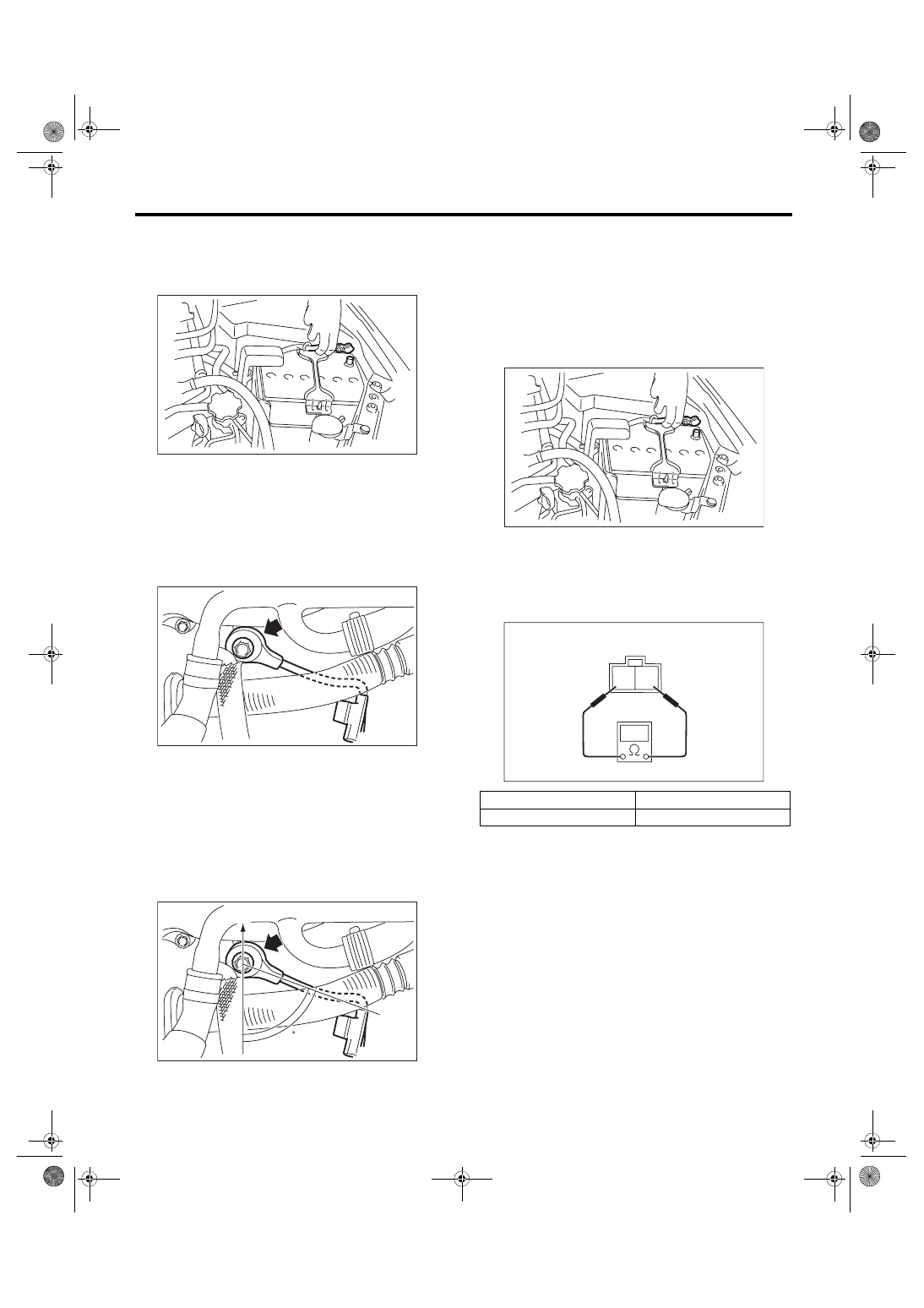
1) Disconnect the ground cable from battery.
2) Remove the intercooler. <Ref. to IN(STI)-12,
3) Remove the intake manifold. <Ref. to FU(STI)-
17, REMOVAL, Intake Manifold.>
4) Remove the secondary air combination valve
RH. <Ref. to EC(STI)-29, REMOVAL, Secondary
5) Remove the knock sensor from cylinder block.
B: INSTALLATION
1) Install the knock sensor to the cylinder block.
NOTE:
The portion of the knock sensor cord that is pulled
out must be positioned at a 60° angle relative to the
engine rear.
Tightening torque:
24 N·m (2.4 kgf-m, 17.7 ft-lb)
2) Install the secondary air combination valve RH.
<Ref. to EC(STI)-30, SECONDARY AIR COMBI-
NATION VALVE RH, INSTALLATION, Secondary
3) Install the intake manifold. <Ref. to FU(STI)-21,
INSTALLATION, Intake Manifold.>
4) Install the intercooler. <Ref. to IN(STI)-13, IN-
5) Connect the battery ground terminal.
C: INSPECTION
1) Check that the knock sensor has no deforma-
tion, cracks or other damages.
2) Measure the resistance between knock sensor
terminals.
(A) Front side of vehicle
IN-00203
FU-04494
FU-05758
60
(A)
Terminal No.
Standard
1 and 2
560±28 kΩ
IN-00203
2 1
EC-02428