Subaru Legacy (2005 year). Manual - part 952


  Index      Subaru     Subaru Legacy - service repair manual 2005 year


Search            


Content   ..  950  951  952  953   ..


Subaru Legacy (2005 year). Manual - part 952


GW-15

GLASS/WINDOWS/MIRRORS

Front Door Glass

10) Make the same adjustment of two adjusting
bolts of rear sash.
ST

61299AE000

SPACER (Glass thickness: 5 
mm (0.197 in) for front door 
glass)

NOTE:
Do not tilt the sash bracket toward inner panel dur-
ing adjustment. Otherwise smooth regulator opera-
tion cannot be achieved. 

11) Make adjustment of front sash in the same
manner as that of rear sash.

NOTE:
Although front and rear sashes must, as a rule, be
adjusted in the same manner, in some door instal-
lation, the adjustment in a different manner may be
required. However, adjustment of one sash to the
maximum amount and the other to the minimum
amount is not permitted. Such adjustment may re-
sult in application of excessive load to regulator. 
12) After adjustments, tighten the nuts.

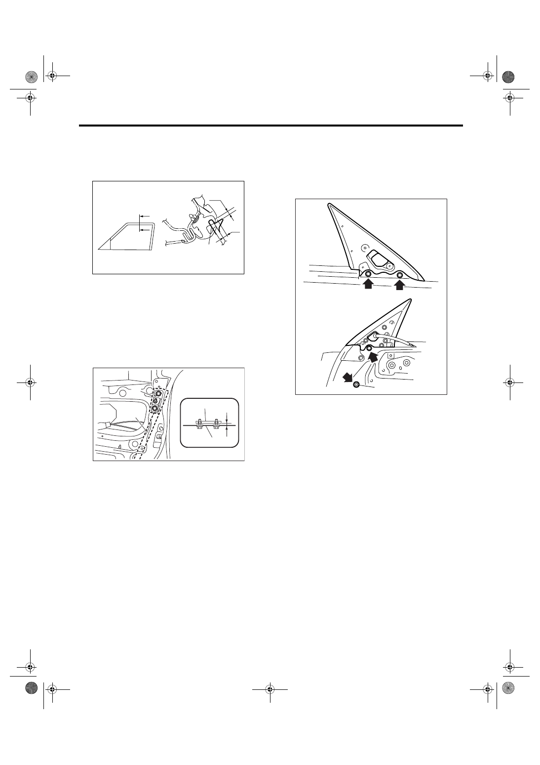
13) After adjustment of the glass, close the door. If
there is a gap between outer lip of gusset and glass
surface, adjust the gap with adjusting bolt (A) in
lower fitting part of gusset to prevent generation of
wind noise.
14) During adjustment, loosen other three clamp-
ing bolts.

15) After adjustment, tighten the bolts and nuts.

(1) 3.2 — 4.8 mm (0.126 — 0.189 in)

(2) When reusing weather strip: 5.5 mm (0.217 in)

With new weather strip: 3 mm (0.118 in)

(3) ST

(1) Sash bracket

(2) Rear sash

(3) Adjust the lines parallel

(4) Sash

(5) Inner panel

GW-00430

A

A

A-A

(1)

(2)

(3)

GW-00270

(1)

(2)

(4)

(3)

(5)

GW-00271

(A)

GW-16

GLASS/WINDOWS/MIRRORS

Front Regulator and Motor Assembly

5. Front Regulator and Motor 

Assembly

A: REMOVAL

1) Remove the door glass. <Ref. to GW-11, RE-
MOVAL, Front Door Glass.>
2) Disconnect the motor connector. 
3) Remove the four bolts and two nuts to remove
regulator assembly.

4) Remove the screws to remove motor assembly.

NOTE:
When removing the motor assembly, secure the
arm correctly. Otherwise the regulator arm moves
with the force of balancing spring.

B: INSTALLATION

1) Install in the reverse order of removal.
2) Adjust the front door glass. <Ref. to GW-12, AD-
JUSTMENT, Front Door Glass.>

Tightening torque:

Refer to “COMPONENT” of “General Descrip-
tion”. <Ref. to GW-4, FRONT DOOR GLASS, 
COMPONENT, General Description.>

C: INSPECTION

1) Make sure that the power window motor rotates
properly when the battery voltage is applied to the
terminals of motor connector.
2) Change polarity of battery connection to termi-
nals to ensure that the motor rotates in reverse di-
rection.

GW-00273

GW-00274

GW-17

GLASS/WINDOWS/MIRRORS

Remote Control Mirror System

6. Remote Control Mirror System

A: WIRING DIAGRAM

<Ref. to WI-305, Remote Control Mirror System.>

B: INSPECTION

Symptom

Repair order

All the functions do not operate.

(1) Fuse (F/B No. 6)
(2) Mirror switch
(3) Wiring harness

One side of the mirror motor does not operate.

(1) Mirror switch
(2) Mirror motor
(3) Wiring harness

Mirror heater does not operate.

(1) Mirror switch
(2) Mirror heater
(3) Wiring harness

GW-18

GLASS/WINDOWS/MIRRORS

Scalp Cap

7. Scalp Cap

A: REPLACEMENT

1) Remove the outer mirror. <Ref. to GW-21, RE-
PLACEMENT, Outer Mirror.>
2) Press-in the upper side clips (A) from the inside
of door mirror.

3) Pull the scalp cap frontward of door mirror, and
remove the upper side clips (A) and lower side
hooks (B) to remove scalp cap.

4) Insert the hook (B) of lower portion of scalp cap
to door mirror, and push the upper clips (A) in.

5) Install the scalp cap securely.

CAUTION:
Do not remove the scalp cap forcibly. The lower 
hooks may be damaged.

GW-00312

(A)

(A)

(A)

GW-00275

(B)

(B)

(A)

GW-00276


Content   ..  950  951  952  953   ..