Subaru Legacy (2005 year). Manual - part 781
VDC-13
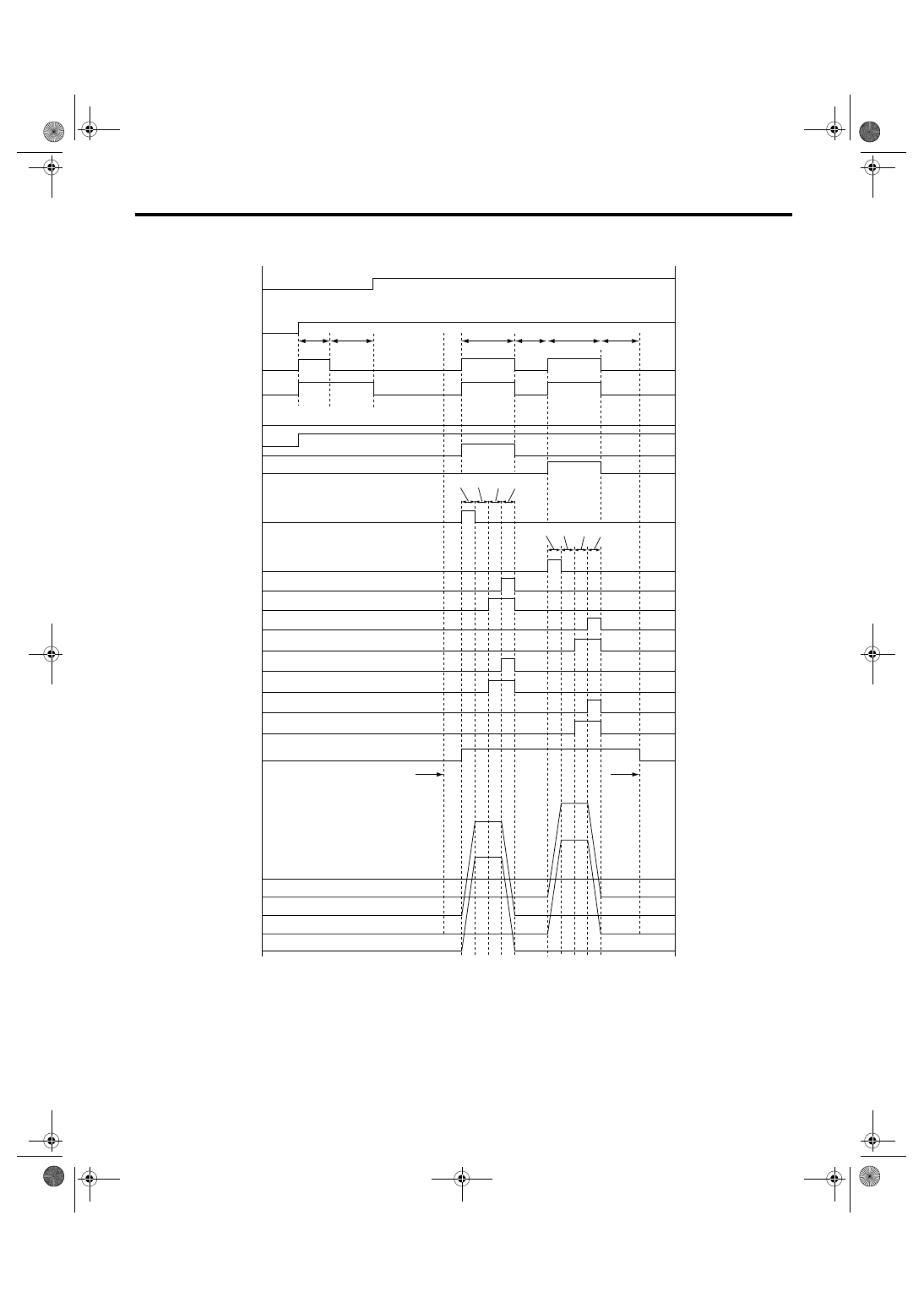
VEHICLE DYNAMICS CONTROL (VDC)
VDC Sequence Control
2. CONDITIONS FOR VDC SEQUENCE CONTROL
(20)
ON
ON
(23)
(23)
(23)
(4)
(5)
(19)
(32)
(3)
(2)
(1)
(22)
(22)
(22)
(22)
V max < 4 km/h (2.5 MPH)
V max < 10 km/h (6 MPH)
OFF
OFF
OFF
OFF
OFF
ON
VDC
(21)
(27)
(28)
(25)
(26)
(24)
(29)
(30) (31)
(25)
(24)
(8)
(7)
(9)
(10)
OFF
(11)
OFF
(12)
OFF
(14)
OFF
(15)
OFF
(16)
OFF
(13)
OFF
(18)
OFF
(17)
(6)
(33)
(35)
(34)
(36)
VDC00275
(29)
(30) (31)
(25)