Subaru Legacy (2005 year). Manual - part 780


  Index      Subaru     Subaru Legacy - service repair manual 2005 year


Search            


Content   ..  778  779  780  781   ..


Subaru Legacy (2005 year). Manual - part 780


VDC-9

VEHICLE DYNAMICS CONTROL (VDC)

VDC Control Module and Hydraulic Control Unit (VDCCM&H/U)

8) Disconnect the pressure gauges from FL and FR
caliper bodies.
9) Install the air bleeder screws of FL and FR cali-
per bodies.
10) Remove the air bleeder screws from the RL
and RR caliper bodies.
11) Connect two pressure gauges to the RL and
RR caliper bodies.
12) Bleed air from the pressure gauges and the RL
and RR caliper bodies.
13) Perform VDC sequence control.
<Ref. to VDC-12, VDC Sequence Control.>
14) When the hydraulic unit begins to work, first the
RR side performs compression, holding, and de-
compression, and then the RL side performs com-
pression, holding, and decompression.
15) Read the values indicated on the pressure
gauges and check it within specification. Depress
the brake pedal and check that it is not abnormally
hard, and tightness is normal.
16) Disconnect the pressure gauge from the RL
and RR caliper bodies.
17) Install the air bleeder screws of RL and RR cal-
iper bodies.
18) Bleed air from the brake line.

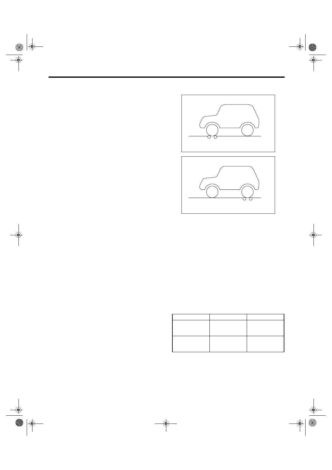
4. CHECK HYDRAULIC UNIT VDC OPERA-
TION WITH BRAKE TESTER

1) Set the wheels other than the measured one on
free rollers.
2) Prepare for operating the VDC sequence con-
trol. <Ref. to VDC-12, VDC Sequence Control.>

3) Set the front wheels or rear wheels on the brake
tester and set the select lever position to “N” range.

4) Operate the brake tester.
5) Perform VDC sequence control.
<Ref. to VDC-12, VDC Sequence Control.>
6) When the hydraulic unit begins to work, check
the following working sequence.

(1) The FL wheel performs compression, hold-
ing and decompression in sequence, and sub-
sequently the FR wheel repeats the cycle.
(2) The RR wheel performs compression, hold-
ing and decompression in sequence, and sub-
sequently the RL wheel repeats the cycle.

7) Read values indicated on the brake tester and
check if the fluctuation of the values between de-
compression and compression meets specifica-
tion.

8) After the inspection, depress the brake pedal
and check that it is not abnormally hard, and tight-
ness is normal.

(1) Brake tester

Front wheel

Rear wheel

When com-
pressed

2,000 N

(203 kgf, 447 lbf)

or more

1,000 N

(102 kgf, 225 lbf)

or more

When decom-
pressed

500 N

(51 kgf, 112 lbf)

or less

500 N

(51 kgf, 112 lbf)

or less

ABS00136

(1)

ABS00137

(1)

VDC-10

VEHICLE DYNAMICS CONTROL (VDC)

VDC Control Module and Hydraulic Control Unit (VDCCM&H/U)

D: ADJUSTMENT

When the following replacement, removal and in-
stallation is performed, be sure to perform the cen-
tering setting of steering angle sensor and zero
point setting of yaw rate & lateral G sensor.
• VDCCM&H/U
• Steering angle sensor
• Yaw rate & lateral G sensor
• Steering wheel parts (Including airbag)
• Suspension parts
• Wheel alignment adjustment
1) Park the vehicle straight on a level surface. (En-
gine operation on “P” or “N” range)
2) Check that steering wheels are positioned in
center. (When the center position is not correct, ad-
just the wheel alignment.)
3) Set the Subaru Select Monitor to vehicle, select
the {Set up mode for Neutral of Steering Angle
Sensor & Lateral G Sensor 0 point} on “Function
check sequence” display. (Follow the step on dis-
play.)
4) On the “Brake Control System” display screen,
select the {Current Data Display & Save}, and
check that the steering angle sensor is displayed “0
deg”.
5) When the “0 deg” is not displayed, repeat the
above steps and check that the “0 deg” is dis-
played.
6) Drive the vehicle for 10 minutes, and check that
the ABS and VDC warning light is not illuminated.
7) Check that the unnecessary operation of VDC,
or losing control of steering is not occurred. And
when the malfunction occurred, repeat the above
steps.

VDC-11

VEHICLE DYNAMICS CONTROL (VDC)

ABS Sequence Control

3. ABS Sequence Control

A: OPERATION

<Ref. to ABS-10, OPERATION, ABS Sequence
Control.>

1. ABS SEQUENCE CONTROL WITH SUB-
ARU SELECT MONITOR

<Ref. to ABS-10, ABS SEQUENCE CONTROL
WITH SUBARU SELECT MONITOR, OPERA-
TION, ABS Sequence Control.>

2. CONDITIONS FOR ABS SEQUENCE 
CONTROL

<Ref. to ABS-11, CONDITIONS FOR ABS SE-
QUENCE CONTROL, OPERATION, ABS Se-
quence Control.>

B: SPECIFICATION

1. CONDITIONS FOR COMPLETION OF 
ABS SEQUENCE CONTROL

<Ref. to ABS-12, CONDITIONS FOR COMPLE-
TION OF ABS SEQUENCE CONTROL, SPECIFI-
CATION, ABS Sequence Control.>

VDC-12

VEHICLE DYNAMICS CONTROL (VDC)

VDC Sequence Control

4. VDC Sequence Control

A: OPERATION

1) While the VDC sequence control is performed,
the operation of the hydraulic unit can be checked
using the brake tester or pressure gauge after the
hydraulic unit solenoid valve is operated.
2) VDC sequence control can be started by Subaru
Select Monitor.

1. VDC SEQUENCE CONTROL WITH SUB-
ARU SELECT MONITOR

NOTE:
In the event of any trouble, the sequence control
does not operate.
1) Connect the Subaru Select Monitor to data link
connector under the driver’s side instrument panel
lower cover.
2) Turn the ignition switch to ON.
3) Set the Subaru Select Monitor power switch to
ON.
4) Set the Subaru Select Monitor to “Brake Control”
mode.
5) When the “VDC Inspection Mode” is selected
from the “Function check sequence” menu, the
“VDC sequence control” will start.
6) Since “Press the [YES] key” is displayed, press
the YES key.
7) Operation points will be displayed on the Subaru
Select Monitor.


Content   ..  778  779  780  781   ..