Subaru Legacy (2005 year). Manual - part 763
 

  Index      Subaru     Subaru Legacy - service repair manual 2005 year


Search            


Content   ..  761  762  763  764   ..


Subaru Legacy (2005 year). Manual - part 763


ABS(diag)-17

ABS (DIAGNOSTICS)

Subaru Select Monitor

3. CLEAR MEMORY MODE

1) On the «Main Menu» display screen, select the
{2. Each System Check} and press the [YES] key.
2) On the «System Selection Menu» display
screen, select the {Brake Control} and press the
[YES] key.
3) Press the [YES] key after the {ABS} is displayed.
4) On the «Brake Control Diagnosis» display
screen, select the {Clear Memory} and press the
[YES] key.

5) When “Done” and “Turn ignition switch OFF” are
shown on the display screen, turn the Subaru Se-
lect Monitor power switch and ignition switch to
OFF.

NOTE:
For details concerning operation procedure, refer
to the SUBARU SELECT MONITOR OPERATION
MANUAL.

4. ABS SEQUENCE CONTROL

5. FREEZE FRAME DATA

NOTE:
• Data stored at the time of trouble occurrence is
shown on display.
• Each time trouble occurs, the latest information
is stored in the freeze frame data in memory.
• Freeze frame data will be memorized up to three.
• If a Freeze Frame Data is not properly stored in
memory (due to a drop in ABS control module pow-
er supply, etc.), the DTC which is suffixed with a
question mark “?” appears on the Subaru Select
Monitor display. This shows it may be an unreliable
reading.

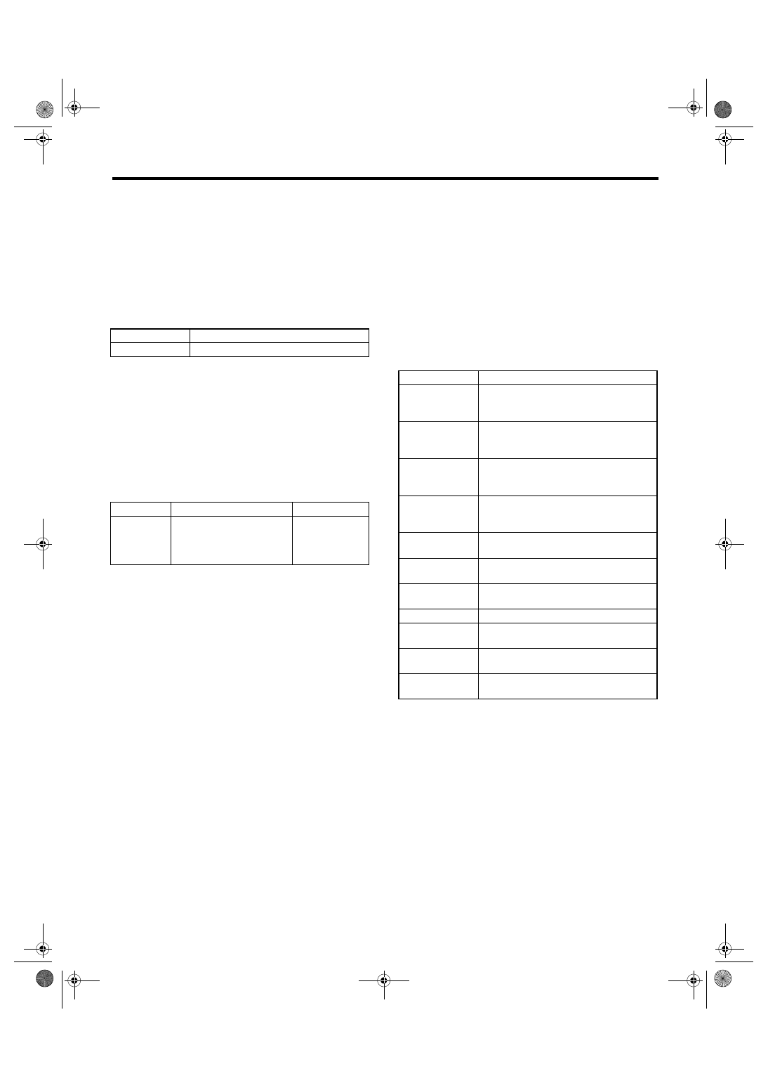
Display

Contents to be monitored

Clear memory?

Function of clearing DTC.

Display

Contents to be monitored

Index No.

ABS 
sequence 
control

Operate the valve and 
pump motor continuously 
to perform the ABS 
sequence control.

<Ref. to ABS-
10, ABS 
Sequence Con-
trol.>

Display

Contents to be monitored

FR Wheel

Wheel speed detected by the Front ABS 
wheel speed sensor RH is displayed in 
km/h or MPH.

FL Wheel

Wheel speed detected by the Front ABS 
wheel speed sensor LH is displayed in 
km/h or MPH.

RR Wheel

Wheel speed detected by the Rear ABS 
wheel speed sensor RH is displayed in 
km/h or MPH.

RL Wheel

Wheel speed detected by the Rear ABS 
wheel speed sensor LH is displayed in 
km/h or MPH.

IG power supply 
voltage

Voltage supplied (V) to ABSCM&H/U is 
displayed.

G Sensor

Vehicle acceleration detected by analog 
G sensor is displayed.

Motor relay mon-
itor

Motor relay condition is displayed.

BLS Signal

Brake ON/OFF is displayed.

Vehicle speed

Vehicle speed calculated by ABS control 
module is displayed.

ABS Control 
Flag

ABS control condition is displayed.

Power Supply 
Failure

Whether abnormal voltage occurred or 
not is displayed during malfunction.

ABS(diag)-18

ABS (DIAGNOSTICS)

Subaru Select Monitor

B: INSPECTION

1. COMMUNICATION FOR INITIALIZING IMPOSSIBLE

DETECTING CONDITION:
Defective harness connector
TROUBLE SYMPTOM:
Communication is impossible between ABS and Subaru Select Monitor.
WIRING DIAGRAM:

ABS00621

B301

B40

1 2 3 4 5 6 7 8

9 10 11 12 13 14 15 16

MAIN SBF

SBF-6

No.33

B40

B301

E

E

1

10

7

15

18

ABSCM & H/U

1 2 3 4 5 6 7 8 9 10 11

16 17 18 19 20 21 22 23 24 25 26

13

12

15

14

IGNITION
SWITCH

BATTERY

DATA LINK 
CONNECTOR

No.13

ABS(diag)-19

ABS (DIAGNOSTICS)

Subaru Select Monitor

Step

Check

Yes

No

1

CHECK IGNITION SWITCH.

Does the ignition switch turn to 
ON?

Go to step 2.

Turn the ignition 
switch to ON, and 
select ABS mode 
using Subaru 
Select Monitor.

2

CHECK BATTERY.
1) Turn the ignition switch to OFF.
2) Measure the battery voltage.

Is the voltage more than 11 V? Go to step 3.

Charge or replace 
the battery.

3

CHECK BATTERY TERMINAL.

Is there poor contact at battery 
terminal?

Repair or tighten 
the battery termi-
nal.

Go to step 4.

4

CHECK SUBARU SELECT MONITOR COM-
MUNICATION.
1) Turn the ignition switch to ON.
2) Using Subaru Select Monitor, check 
whether communication to other system can 
be executed normally.

Is the system name and model 
year displayed on Subaru 
Select Monitor?

Go to step 8.

Go to step 5.

5

CHECK SUBARU SELECT MONITOR COM-
MUNICATION.
1) Turn the ignition switch to OFF.
2) Disconnect the ABSCM&H/U connector.
3) Turn the ignition switch to ON.
4) Check whether communication to other 
systems can be executed normally.

Is the system name and model 
year displayed on Subaru 
Select Monitor?

Replace 
ABSCM&H/U. 
<Ref. to ABS-6, 
ABS Control Mod-
ule and Hydraulic 
Control Unit 
(ABSCM&H/U).>

Go to step 6.

6

CHECK HARNESS CONNECTOR BETWEEN 
EACH CONTROL MODULE AND DATA LINK 
CONNECTOR.
1) Turn the ignition switch to OFF.
2) Disconnect ABSCM&H/U, ECM and TCM.
3) Measure the resistance between data link 
connector and chassis ground.

Connector & terminal

(B40) No. 10 — Chassis ground:

Is the resistance more than 1 
M

Ω?

Go to step 7.

Repair the har-
ness and connec-
tor between each 
control module 
and data link con-
nector.

7

CHECK OUTPUT SIGNAL FOR ABSCM&H/
U.
1) Turn the ignition switch to ON.
2) Measure the voltage between data link con-
nector and chassis ground.

Connector & terminal

(B40) No. 10 (+) — Chassis ground (

):

Is the voltage less than 1 V?

Go to step 8.

Repair the har-
ness and connec-
tor between each 
control module 
and data link con-
nector.

8

CHECK HARNESS CONNECTOR BETWEEN 
ABSCM&H/U AND DATA LINK CONNEC-
TOR.
Measure the resistance between ABSCM&H/U 
connector and data link connector.

Connector & terminal

(B301) No. 7 — (B40) No. 10: 

Is the resistance less than 0.5 
Ω?

Go to step 9.

Repair the har-
ness and connec-
tor between 
ABSCM&H/U and 
data link connec-
tor.

9

CHECK INSTALLATION OF ABSCM&H/U 
CONNECTOR.
Turn the ignition switch to OFF.

Is the ABSCM&H/U connector 
inserted into ABSCM&H/U until 
it is locked by clamps?

Go to step 10.

Insert ABSCM&H/
U connector into 
ABSCM&H/U.

10

CHECK POWER SUPPLY CIRCUIT.
1) Turn the ignition switch to ON. (engine 
OFF)
2) Measure the ignition power supply voltage 
between ABSCM&H/U connector and chassis 
ground.

Connector & terminal

(B301) No. 18 (+) — Chassis ground (

):

Is the voltage 10 — 15 V?

Go to step 11.

Repair the open 
circuit in harness 
between 
ABSCM&H/U and 
battery.

ABS(diag)-20

ABS (DIAGNOSTICS)

Subaru Select Monitor

2. WITHOUT DTC

DETECTING CONDITION:
• Defective combination meter
• Open in harness
TROUBLE SYMPTOM:
• ABS warning light does not go off.
• “NO TROUBLE CODE” will be displayed on the Subaru Select Monitor.

NOTE:
When the ABS warning light is OFF and “NO TROUBLE CODE” is displayed on Subaru Select Monitor, the
system is in normal condition.

11

CHECK HARNESS CONNECTOR BETWEEN 
ABSCM&H/U AND CHASSIS GROUND.
1) Turn the ignition switch to OFF.
2) Disconnect the connector from ABSCM&H/
U.
3) Measure the resistance of harness 
between ABSCM&H/U connector and chassis 
ground.

Connector & terminal

(B301) No. 15 — Chassis ground:

Is the resistance less than 0.5 
Ω?

Go to step 12.

Repair the open 
circuit in harness 
between 
ABSCM&H/U and 
inhibitor side con-
nector, and poor 
contact in cou-
pling connector.

12

CHECK POOR CONTACT IN CONNECTOR. Is there poor contact in control 

module power supply, ground 
circuit and data link connector?

Repair the con-
nector.

Replace the 
ABSCM only. 
<Ref. to ABS-8, 
REPLACEMENT, 
ABS Control Mod-
ule and Hydraulic 
Control Unit 
(ABSCM&H/U).>

Step

Check

Yes

No


Content   ..  761  762  763  764   ..