Subaru Legacy (2005 year). Manual - part 692
6MT-115
MANUAL TRANSMISSION AND DIFFERENTIAL
Shifter Fork and Rod
2) Install the reverse interlock block and interlock
block to striking rod.
NOTE:
Be sure the reverse interlock block and interlock
block are installed in proper direction.
E: INSPECTION
1) Check the shift shaft and shift rod for damage.
Replace if damaged.
2) Repair or replace the gear shift mechanism if ex-
cessively worn, bent or defective in any way.
F: ADJUSTMENT
1. SELECTION OF 1ST-2ND FORK ROD
NOTE:
Perform the procedures below in the following cas-
es.
• When replacing the 1st and 2nd driven gear.
• When replacing the 1st and 2nd synchro ring as-
sembly.
• When replacing the adapter plate.
• When replacing the driven shaft.
• When replacing the 1st-2nd hub and sleeve as-
sembly.
1) Insert the drive pinion assembly in adapter plate.
NOTE:
Make sure the thrust bearing outer race is not re-
moved and drive pinion is not lifted-up.
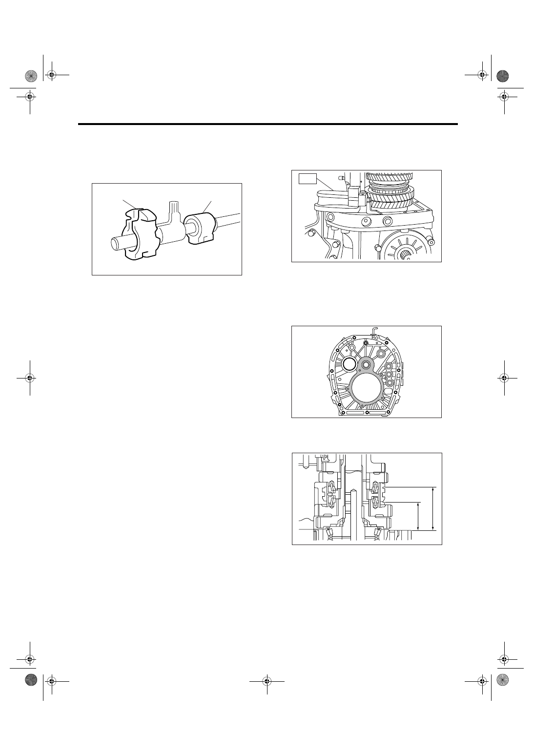
2) Set the height gauge to adapter plate. Lower the
indicator of height gauge to mating surface of
adapter plate and case, then set to zero point.
ST
18853AA000
HEIGHT GAUGE
NOTE:
• Remove the remaining gasket on edge surface
with scraper, since the adapter plate is base point
of measurement.
• Do not place the height gauge on shaded area in
the figure during the measurement.
3) Select the main shaft snap ring. <Ref. to 6MT-
81, ADJUSTMENT, Main Shaft Assembly.>
4) Measure “B1” and “B2” as shown in the figure.
(A) Reverse interlock block
(B) Interlock block
(A)
(B)
MT-00688
MT-00582
ST
MT-00583
MT-00979
B1
B2