Subaru Legacy (2005 year). Manual - part 690
6MT-107
MANUAL TRANSMISSION AND DIFFERENTIAL
Front Differential Assembly
3) Install the O-ring.
NOTE:
Use a new O-ring.
E: INSPECTION
Repair or replace the front differential in following
cases.
• When each gear is damaged, seized, or exces-
sively worn.
• When sliding surfaces of the differential case is
damaged, seized or excessively worn.
• When bearings and bearings part is damaged,
rusted or worn.
• When bearing that fails to turn smoothly or
makes noise when turned.
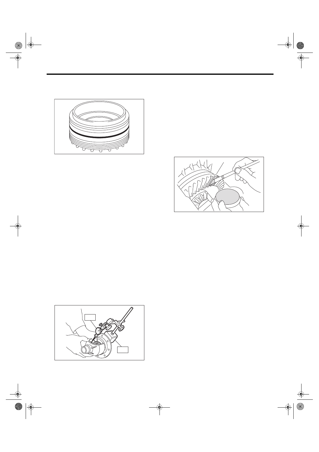
1. BEVEL PINION GEAR BACKLASH
Measure the bevel pinion gear backlash. If it is not
within specification, install a suitable washer to ad-
just. <Ref. to 6MT-108, ADJUSTMENT, Front Dif-
ferential Assembly.>
NOTE:
• Be sure the pinion gear teeth contact adjacent
gear teeth during measurement.
• Before measuring the backlash, rotate each gear
to get each part accustomed.
ST1
498247001
MAGNET BASE
ST2
498247100
DIAL GAUGE
Standard backlash:
0.13 — 0.18 mm (0.0051 — 0.0071 in)
2. HYPOID GEAR BACKLASH
Check the hypoid gear backlash. If it is not within
specification, adjust it. <Ref. to 6MT-108, HYPOID
GEAR BACKLASH, ADJUSTMENT, Front Differ-
ential Assembly.>
3. TOOTH CONTACT OF HYPOID GEAR
1) Be sure the hypoid gear backlash is within spec-
ification. If it is not within specification, adjust it.
<Ref. to 6MT-108, HYPOID GEAR BACKLASH,
ADJUSTMENT, Front Differential Assembly.>
2) Apply a uniform thin coat of red lead on both
tooth surfaces of three or four teeth of the hypoid
driven gear.
3) Install the drive pinion shaft assembly, and then
secure with four bolts.
NOTE:
Use the old gasket and washer to prevent the mat-
ing surface of housing from damaging.
Tightening torque:
50 N
⋅
m (5.1 kgf-m, 36.9 ft-lb)
4) Rotate the drive pinion shaft to right and left for
several times.
AT-00219
ST1
ST2
MT-00672
MT-00652