Subaru Legacy (2005 year). Manual - part 515


  Index      Subaru     Subaru Legacy - service repair manual 2005 year


Search            


Content   ..  513  514  515  516   ..


Subaru Legacy (2005 year). Manual - part 515


4AT-41

AUTOMATIC TRANSMISSION

Automatic Transmission Assembly

25) Remove the front, center and rear exhaust
pipes and muffler.
<Ref. to EX(H4SO 2.0)-6, REMOVAL, Front Ex-
haust Pipe.> <Ref. to EX(H4SO 2.0)-10, REMOV-
AL, Rear Exhaust Pipe.> <Ref. to EX(H4SO 2.0)-
12, REMOVAL, Muffler.>
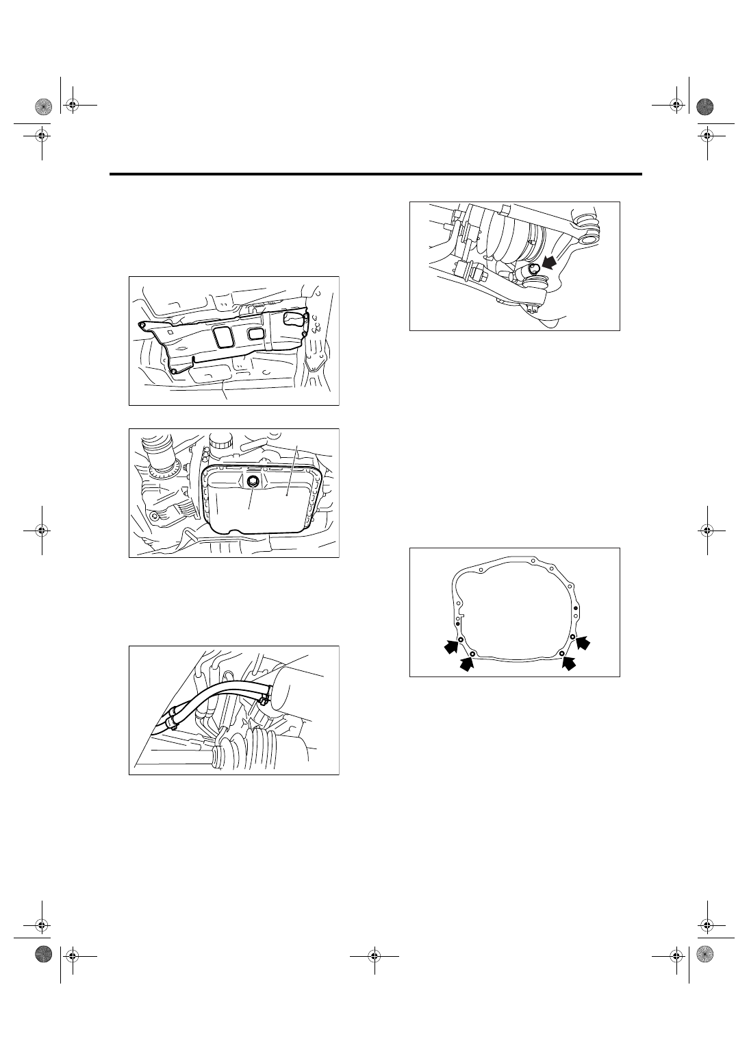
26) Remove the heat shield cover.

27) Remove the ATF drain plug to drain ATF.

28) Disconnect the ATF cooler hoses from pipes of
transmission side, and remove the oil charge pipe.
(Model without ATF cooler with warmer function)

29) Remove the propeller shaft.
<Ref. to DS-10, REMOVAL, Propeller Shaft.>
30) Remove the shift select cable.
<Ref. to CS-27, REMOVAL, Select Cable.>
31) Remove the brackets (two) which hold front
stabilizer.

32) Remove the ball joint of front arm from housing.

33) Pull out the front drive shaft from transmission.

(1) Using a tire lever or a pinch bar, etc., pull out
the front drive shaft until its joint facing to trans-
mission can move smoothly.

NOTE:
Place a cloth between tire lever or pinch bar and
transmission in order to avoid damaging the side
retainer of transmission.

(2) Hold the transmission side joint portion of
front drive shaft by hand and extract the housing
from the transmission by pressing it outside so
as not to stretch the boot.

34) Remove the bolts which hold the clutch hous-
ing cover.
35) Remove the bolts which install lower side of the
transmission to engine.

36) Place the transmission jack under transmis-
sion.

NOTE:
Make sure that the support plates of transmission
jack do not touch the oil pan.

(A) Oil pan

(B) ATF drain plug

AT-01331

AT-01332

(B)

(A)

AT-01333

AT-00809

AT-00108

4AT-42

AUTOMATIC TRANSMISSION

Automatic Transmission Assembly

37) Remove the transmission rear crossmember
from the vehicle.

38) While lowering the transmission jack gradually,
retract the engine support fully, and then tilt the en-
gine backward.

NOTE:
Retract the support until the clearance between
front crossmember and torque converter case be-
comes approx. 10 mm (0.39 in).
39) Remove the transmission.

CAUTION:
Remove the transmission and torque converter 
as a unit from engine.

40) Remove the rear cushion rubber from transmis-
sion assembly.

B: INSTALLATION

1) Replace the differential side oil seal with new
one.

NOTE:
When a new oil seal has been installed, the re-
placement is not required.
2) Install the rear cushion rubber to transmission
assembly.

Tightening torque:

40 N

m (4.1 kgf-m, 29.5 ft-lb)

3) Install the ST to converter case.
ST

498277200

STOPPER SET

4) Install the transmission onto engine.

(1) Lift up the transmission gradually using a
transmission jack.

(2) Engage them at spline portion.
(3) While lowering the transmission jack gradu-
ally, rotate the screw of engine support, and
then tilt the engine forward.

5) Install the transmission rear crossmember.

Tightening torque:

T1: 35 N

m (3.6 kgf-m, 26 ft-lb)

T2: 70 N

m (7.1 kgf-m, 51.6 ft-lb)

6) Take off the transmission jack.

AT-01334

AT-00109

AT-00103

ST

AT-00109

AT-01335

T2

T2

T1

4AT-43

AUTOMATIC TRANSMISSION

Automatic Transmission Assembly

7) Tighten the bolts which install lower side of
transmission to engine.

Tightening torque:

50 N

m (5.1 kgf-m, 36.9 ft-lb)

8) Screw the bolts for the clutch housing cover.
9) Lower the lift.
10) Connect the engine and transmission.

(1) Remove the ST from converter case.

NOTE:
When removing the ST, be careful not to drop it into
converter case.
ST

498277200

STOPPER SET

(2) Install the starter.
<Ref. to SC(H4SO 2.0)-6, INSTALLATION,
Starter.>
(3) Tighten the bolts which install upper side of
transmission to engine.

Tightening torque:

50 N

m (5.1 kgf-m, 36.9 ft-lb)

11) Install the torque converter clutch to drive plate.

(1) Tighten the bolts which install torque con-
verter clutch to drive plate.
(2) Insert the wrench to crank pulley bolt, and
then tighten all bolts while slightly rotating the
crank pulley.

Tightening torque:

25 N

m (2.5 kgf-m, 18.4 ft-lb)

(3) Install the plug to service hole.
(4) Install the V-belt cover.

12) Remove the ST.

13) Install the bracket of warmer cock assembly.
(Model with ATF cooler with warmer function)

Tightening torque:

16 N

m (1.6 kgf-m, 11.6 ft-lb)

AT-00108

AT-00106

AT-00102

AT-02167

ST

AT-02166

4AT-44

AUTOMATIC TRANSMISSION

Automatic Transmission Assembly

14) Install the warmer cock assembly. (Model with
ATF cooler with warmer function)

Tightening torque:

T1: 6.4 N

m (0.65 kgf-m, 4.7 ft-lb)

T2: 15 N

m (1.5 kgf-m, 11.1 ft-lb)

15) Connect each hose to warmer cock assembly.
(Model with ATF cooler with warmer function)

16) Install the pitching stopper bracket and bracket
(Model with ATF cooler with warmer function).

Tightening torque:

41 N

m (4.2 kgf-m, 30.4 ft-lb)

17) Install the ATF cooler with warmer function to
transmission. (Model with ATF cooler with warmer
function)

Tightening torque:

23 N

m (2.3 kgf-m, 17 ft-lb)

18) Connect the ATF cooler inlet and outlet hoses
to ATF cooler pipes. (Model with ATF cooler with
warmer function)

19) Install the throttle body. <Ref. to FU(H4SO
2.0)-10, INSTALLATION, Throttle Body.>

(A) Pitching stopper bracket

(B) Bracket (Model with ATF cooler with warmer 

function)

AT-02168

T1

T2

AT-02163

AT-02169

(A)

(B)

AT-03199

AT-02171


Content   ..  513  514  515  516   ..