Content .. 1012 1013 1014 1015 ..
Subaru Legacy (2005 year). Manual - part 1014
CC-3
CRUISE CONTROL SYSTEM
General Description
B: CAUTION
• Before disassembling or reassembling parts, al-
ways disconnect the battery ground cable from bat-
tery. When repairing the audio, control module, etc.
which are provided with memory functions, record
the memory contents before disconnecting the
ground cable from battery. Otherwise, the memory
will be erased.
• Reassemble the parts in the reverse order of dis-
assembly unless otherwise indicated.
• Adjust the parts to specifications specified in this
manual.
• Connect the connectors securely during reas-
sembly.
• After reassembly, ensure functional parts oper-
ate properly.
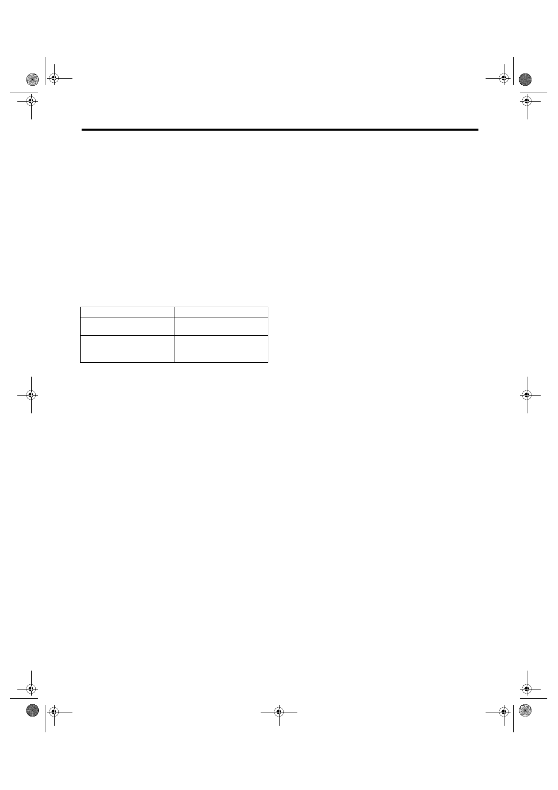
C: PREPARATION TOOL
TOOL NAME
REMARKS
Circuit tester
Used for measuring resis-
tance and voltage.
TORX
®
BIT T30
Used for removing and
installing driver’s airbag
module.