SsangYong Musso. Manual - part 486


  Index      SsangYong     SsangYong Musso - service repair manual


Search            


Content   ..  484  485  486  487   ..


SsangYong Musso. Manual - part 486


AUTOMATIC TRANSMISSION  5A-121

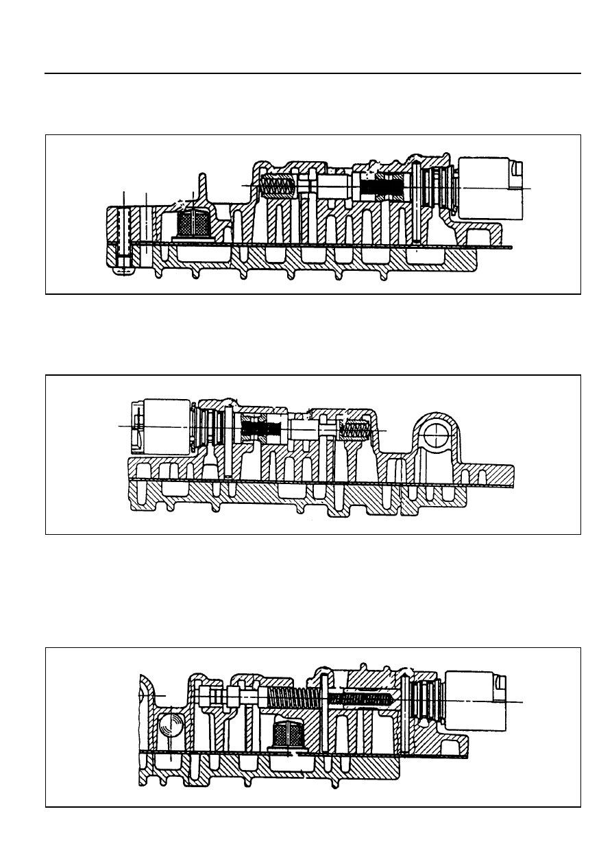
12. Install the band apply regulator (BAR) valve (refer to figure

8.54), springs, plunger and retainer pin.

Figure 8.54 - Band Apply Regulator Valve and Solenoid 4

13. Install the clutch apply regulator (CAR) valve (refer to figure

8.55), springs, plunger and retainer pin.

Figure 8.55 - Clutch Apply Regulator Valve and solenoid 3

14. Install the solenoid supply valve, spring and retainer plate.

Refer to figure 8.56.

Notice

This aluminum valve is easily damaged.

Figure 8.56 - Solenoid Supply Valve and Solenoid 6

5A-122  AUTOMATIC TRANSMISSION

15. Install solenoid 6 plunger, spring and retaining pin.

16. Position the third feed ball (large nylon) in the valve body

and install the solenoid 5 filter and the solenoid 6 filter.
Refer to figures 8.5  and 8.56.

17. Check the separator plate for burrs and damage. Repair

or replace the separator plate as necessary.

18. Check the upper and lower valve body gaskets for

damage. Replace the gaskets as necessary.

19. Install the lower valve body gasket on the lower valve body.

20. Install the reverse lockout valve, spring, plug and retainer

plate. Ensure that the valve is correctly oriented. Refer to
figure 8.57.

Figure 8.57 - Reverse Lockout Valve

21. Position the five nylon ball checks in the upper valve body.

Refer to figure 8.48.

22. Fit the upper valve body gasket. Install the separator plate

over the upper valve body.

AUTOMATIC TRANSMISSION  5A-123

23. Holding the separator plate to the upper valve body to

prevent the check balls from falling out, install the upper
valve body on the lower valve body. Install all screws finger
tight then tighten the screws to specification in the
prescribed sequence. Refer to figure 8.58.

24. Install solenoids 1,2,3,4 and 6. Ensure the solenoid is firmly

secured by the retainer and that the screw is tightened to
specification.

25. Install solenoid 5. Ensure that the solenoid is pushed firmly

into the valve body by the retainer.

Notice

The wiring loom ground wire eyelet terminal is secured
beneath the solenoid retainer.

26. Install the line pressure relief valve, tapered end first, (refer

to figure 8.59), and the spring and disc. Secure with the
retaining pin.

Figure 8.58 - Tightening Sequence Upper to Lower Valve Body

Figure 8.59 - Line Pressure Relief Valve

5A-124  AUTOMATIC TRANSMISSION

27. Install the line pressure plug and tighten to specification.

Refer to figure 8.62.

28. Install the detent spring assembly (spring, support plate

and screw), ensuring that the screw is tightened to
specification. Check the spring for wear or damage.

29. Install the manual shift valve. Refer to figure 8.60.

Notice

Be aware that the manual valve will fall out of the valve
body.

Figure 8.62 - Wiring Installation

Figure 8.60 - Manual Shift Valve


Content   ..  484  485  486  487   ..