SsangYong Musso. Manual - part 484


  Index      SsangYong     SsangYong Musso - service repair manual


Search            


Content   ..  482  483  484  485   ..


SsangYong Musso. Manual - part 484


AUTOMATIC TRANSMISSION  5A-113

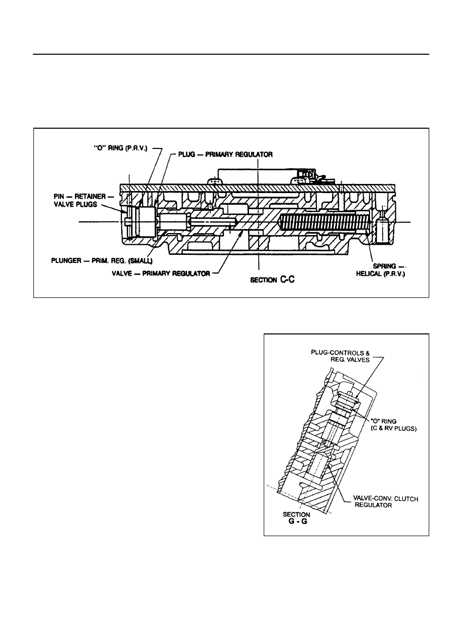
9. Assemble the primary regulator valve and plunger (refer

to figure 8.36) to the pump cover, ensuring that the
regulator valve slides freely, then fit the regulator valve
plug and ‘O’ ring.

10. Install the retaining pin.

11. Install the converter clutch regulator valve (refer to figure

8.37), plug, and ‘O’ ring.

Figure 8.36 - Primary Regulator Valve

Figure 8.37 - Converter Clutch Regulator Valve

5A-114  AUTOMATIC TRANSMISSION

13. Install the converter clutch control valve (refer to figure

8.38), spring, plug, and ‘O’ ring.

14. Install the retaining pin. Refer to figure 8.39.

Figure 8.39 - Valve Retaining Plugs and Pins

Figure 8.38 - Converter Clutch Control Valve

12. Install the retaining pin. Refer to figure 8.39.

AUTOMATIC TRANSMISSION  5A-115

15. Install the C1 bias valve spring, valve, plug and ‘O’ ring.

Refer to figure 8.40.

16. Install the retaining pin. Refer to figure 8.39.

17. Install the converter release check ball and spring and the

feed ball. Refer to figures 8.41,  8.42 and 8.43.

Figure 8.40 - C1 Bias Valve

Figure 8.41 - Converter Relief Ball and Spring

Figure 8.42 - Peed Ball

Figure 8.42 - Feed Ball

5A-116  AUTOMATIC TRANSMISSION

18.  Install the gasket on the pump cover.

19.  Install the cover plate, solenoid 7 with the retainer and the

solenoid wiring retainer to the pump cover, ensuring that
the periphery of the cover plate is flush with the periphery
of the pump cover. Refer to figure 8.34.

Tighten the screws to specification in the order (1-5), shown
in figure 8.44.

24. Install the pump and cover assembly over the input shaft

being careful not to damage the sealing rings. Tighten the
pump cover to case bolts to specification. Refer to figure
8.45.

20. Tighten the solenoid 7 screw. Refer to figure 8.39.

Notice

Check that neither the wiring nor the connector protrudes
excessively, in order that at assembly neither the wiring
and the connector contacts or rubs on the input shaft or
the C1/C2 clutch cylinder.

21. Assemble the pump to the pump cover.

Tighten all bolts and the crescent screw finger tight,
ensuring that the pump is flush against the pump cover.
Tighten the bolts and the screw to specification in the order
(A - F), shown in figure 8.44.

22. Install the pump to transmission case gasket onto the case.

23. Fit the ‘O’ ring to the pump cover outer diameter.

Figure 8.44 - Pump Bolt Tightening Sequence

Figure 8.45 - Tightening Sequence Pump to

      Case


Content   ..  482  483  484  485   ..