SsangYong Musso. Manual - part 483


  Index      SsangYong     SsangYong Musso - service repair manual


Search            


Content   ..  481  482  483  484   ..


SsangYong Musso. Manual - part 483


AUTOMATIC TRANSMISSION  5A-109

Forward Sun Gear and C3 Clutch Pack Assembly

To assemble the forward sun gear and C3 clutch pack assembly
(Refer to figure 8.30), proceed as follows:

1. Fit the No. 7 needle thrust bearing assembly over the forward

sun gear, ensuring that the thrust washer is between the
bearing and the sun gear.

2. Lubricate the thrust plate with petroleum jelly and fit the

thrust plate onto the reverse sun gear.

Refer to figure 8.33.

3.  Align and fit the C3 clutch assembly over the forward sun

gear.

4.  Lubricate the No. 6 needle thrust bearing with petroleum

jelly and fit it to the thrust plate. Ensure the lugs on the
outside diameter of the bearing fit in the thrust plate
counterbore.

Refer to figure 8.19.

5.  Align and fit the plastic thrust washer to the thrust plate with

petroleum jelly.

Refer to to figures 8.19.

6.  Install the assembly over the forward sun gear shaft against

the No.6 thrust bearing.

Refer to figure 8.19.

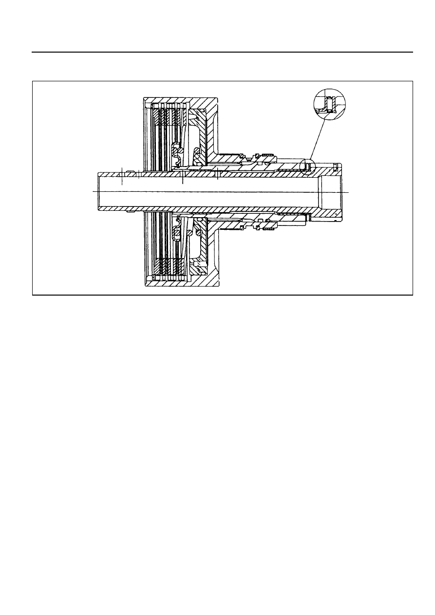
7. Place the assembly to one side.

Figure 8.30 - Typical forward Sun Gear add C3 Clutch Assembly

5A-110  AUTOMATIC TRANSMISSION

C1 Clutch Overdrive Shaft and Input Shaft
Assembly

Notice

1. Ensure that the snap rings are fitted correctly.

2. Check pistons for cracks, especially the C1 piston.

3. Do not mix clutch piston return springs.

4. If the C1/C2 clutch packs separate from the C3 clutch pack,

make sure the No. 6 bearing doesn’t drop out of the bearing
retainer.

To assemble the C1 clutch overdrive shaft and input shaft
assembly, proceed as follows:

1.  Check the overdrive shaft grooves for any defect.

2.  Coat the sealing rings, large and small, with petroleum jelly

and fit them to the overdrive shaft. The sealing rings may
be held in place with a small amount of petroleum jelly.

3.  Assemble the clutch plate and disc into the cylinder in the

following sequence:

!

steel plate

!

friction disc

!

steel plate

!

friction disc

!

steel plate

!

steel plate - 0574-GOOGOl, 0574-000003,

0574-000004, 0574-000005, 0574-000020,

0574-000021, or friction disc -0574-000002

!

steel plate (selective)

!

friction disc

!

steel plate (selective)

!

friction disc

4.  Check the clutch pack clearance using special tool No.0555-

331900. Refer to figure 8.31.

Use selective plates to achieve the correct specification.

Notice

The clutch pack supporting a 2 kg weight, the dimension
from the input shaft locating stop to the friction disc must
be 0.70-0.90 mm.

5.  If new friction plates are being fitted, remove the clutch pack

and soak the friction elements in automatic transmission
fluid for a minimum of five minutes prior to assembly.

Notice

The clutch pack clearance must be taken before
elements are soaked in automatic transmission fluid.

6.  Check the fit of the C1 clutch hub on the overdrive shaft. If

it is loose, the hub and shaft assembly must be replaced.

Figure 8.31 - Typical C1 Clutch Assembly

 Clearance

AUTOMATIC TRANSMISSION  5A-111

7. Coat the small nylon thrust spacer with petroleum jelly and

install it over the overdrive shaft. Refer to figure 8.19.

8. Carefully fit the overdrive shaft into the C1 cylinder so as

not to damage the sealing ring.

9. Fit the small bronze C1 hub thrust washer in place with

petroleum jelly. Refer to figure 8.19.

10. Check the input shaft for any defect. Fit the input shaft

into the cylinder and secure it with the circlip, ensuring
that the circlip is completely seated in the groove.

11.  Coat the sealing rings with petroleum jelly and fit onto the

input shaft.

12. Assemble the C1/C2/C4 clutch assembly to  the C3 clutch

and sun gear assembly. Refer to figures 8.32 and 8.33.

13. Install this assembly in the transmission case.

5A-112  AUTOMATIC TRANSMISSION

Pump Cover  and Converter Support

Notice

1. Do not wash the nose of solenoids in solvent.

2. Ensure that the correct ‘O’ ring is fitted for the application.

3. Do not mix up the low first blow-off and the torque converter

blow-off ball springs.

4. Be careful not to damage the needle bearings on the

assembly. Avoid any axial impact loads during assembly.

5. Check the transmission end float. This will help to detect

any missing parts or incorrect assembly.

Notice

Figure 8.35 shows the orientation of the cross- sections for
figures 8.36 to 8.42.

To assemble the pump cover and converter support

(refer to figures 8.34 and 8.35), proceed as follows.

1. Check the pump body for any damage, chips or irregularity.

Check that the bush is firmly staked in the drive gear.

2.  Install the seal flush with the front face of the pump body.

3.  Lubricate the pump bush, and the drive and driven gears,

with automatic transmission fluid.

4.  Install the pump driven gear and the pump drive gear into

the pump body.

5.  Using a straight edge and thickness gauge, check that the

clearance between pump face and gears is 0.04 - 0.018
mm.

6.  Lubricate the pump body ‘O’ ring with automatic transmission

fluid and fit it to the pump body. Put the pump body to one
side.

7.  Ensure that the pump cover cavities, ports and holes are

clean and free of any obstruction.

8.  Lubricate all loose parts with automatic transmission fluid

prior to assembly.

Figure 8.34 - Pump, Cover and Converter

      Support

Figure 8.35 - Pump Cover Assembly


Content   ..  481  482  483  484   ..