SsangYong Musso. Manual - part 420


  Index      SsangYong     SsangYong Musso - service repair manual


Search            


Content   ..  418  419  420  421   ..


SsangYong Musso. Manual - part 420


1F3-30  OM600 ENGINE CONTROLS

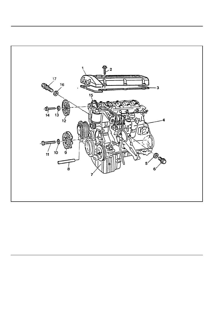
REMOVAL AND INSTALLATION OF INJECTION TIMING DEVICE

Preceding Work : Removal of vacuum pump

1 Cylinder Head Cover
2 Bolt ............................................................ 10Nm
3 Gasket ................................................... Replace
4 Fuel Injection Pump
5 Seal ....................................................... Replace
6 Screw Plug ................................................. 30Nm
7 Oil Pan
8 Locking Pin
9 Injection Timing Device

10 Washer

11 Bolt (Left-Hand Thread) ............................. 46Nm

12 Camshaft Sprocket
13 Washer
14 12-Sided Stretch Bolt ............ Check, 25Nm + 90°
15 Timing Chain
16 Seal
17 Chain Tensioner......................................... 80Nm

OM600 ENGINE CONTROLS  1F3-31

Tools Required

601 589 00 08 00 Flange

601 589 05 21 00 Locking Screw

116 589 20 33 00 Sliding Hammer

116 589 02 34 00 Threaded Bolt

667 589 04 63 00 Retaining Plate

Removal & Installation Procedure

1. Remove the bolts (2) and then remove the cylinder head

cover (1) and gasket (3).

Installation Notice

Tightening Torque

10 Nm

Notice

Replace the gasket.

Rotate the engine 1 revolution by hand and check TDC
marking of the crankshaft and camshaft.

2. Loosen the camshaft sprocket bolt (14).

Notice

Do not remove the bolt.

Installation Notice

Notice

If max. length of bolt exceeds 53.6mm, replace it.

Tightening  Torque

25Nm + 90°

3. Loosen the bolt (11) (left-hand thread).

Notice

Do not remove the bolt.

1F3-32  OM600 ENGINE CONTROLS

5. Remove the plug (6) and seal (5) from the fuel injection

pump and collect oil in a suitable vessel.

Installation Notice

Notice

Replace the seal.

Tightening Torque

30 Nm

6. Install the locking screw (18) into the injection pump.

Notice

Before tightening the bolts for the injection timing device
and the camshaft sprocket, always remove the locking screw
from the injection pump and reinstall the plug.

Locking Screw 601 589 05 21 00

7. Place alignment marks (arrow) on the timing chain (12) and

camshaft sprocket (15).

4. Position the no.1 cylinder at ATDC 15°.

Notice

Do not rotate the engine with camshaft sprocket bolt or
opposite direction of the engine rotation.

OM600 ENGINE CONTROLS  1F3-33

9. Pull out the 12-sided stretch bolt (14) and washer and

remove the camshaft sprocket (12).

Tightening Torque

46 Nm

11. Using special tool (24, 25), remove the locking pin (8).

Sliding Hammer 116 589 20 33 00

Threaded Bolt 116 589 02 34 00

8. Remove the chain tensioner (17).

Installation Notice

Tightening Torque

80 Nm

Notice

Replace the seal (16).

10. Pull out the bolt (11) and washer (10).

Notice

Be careful that the bolt is left-hand thread.

Installation Notice


Content   ..  418  419  420  421   ..