SsangYong Musso. Manual - part 234
1A1-6 GENERAL ENGINE INFORMATION
SPECIAL TOOLS
SPECIAL TOOLS TABLE
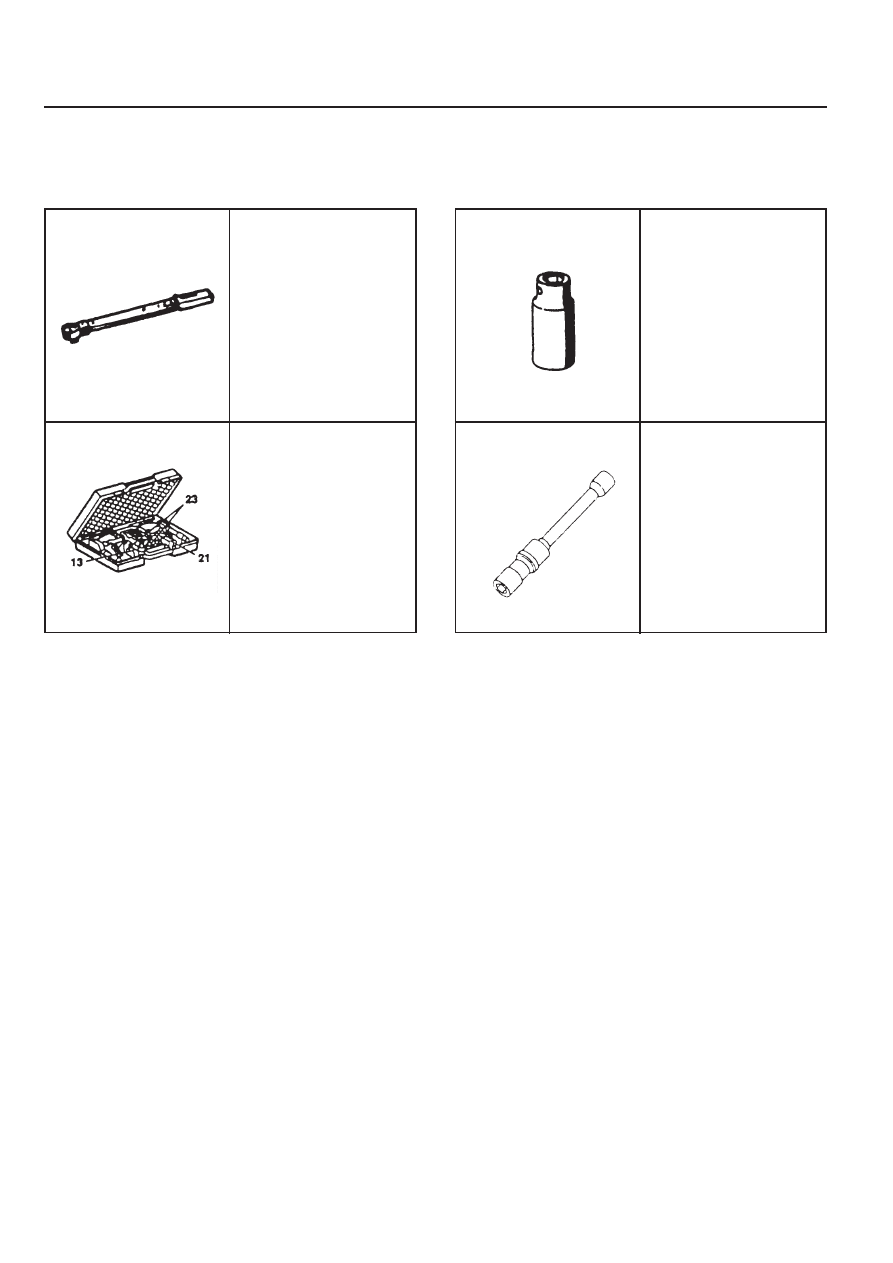
000 589 10 99 01
Torque Wrench
001 589 76 21 00
Compression Pressure
Tester
119 589 01 09 00
Spark Plug Wrench
001 589 65 09 00
Socket
|
|
|
1A1-6 GENERAL ENGINE INFORMATION SPECIAL TOOLS SPECIAL TOOLS TABLE 000 589 10 99 01 Torque Wrench 001 589 76 21 00 Compression Pressure Tester 119 589 01 09 00 Spark Plug Wrench 001 589 65 09 00 Socket |