SsangYong Musso. Manual - part 34


  Index      SsangYong     SsangYong Musso - service repair manual


Search            


Content   ..  32  33  34  35   ..


SsangYong Musso. Manual - part 34


9T-6  REMOTE KEYLESS ENTRY AND ANTI-THEFT SYSTEM
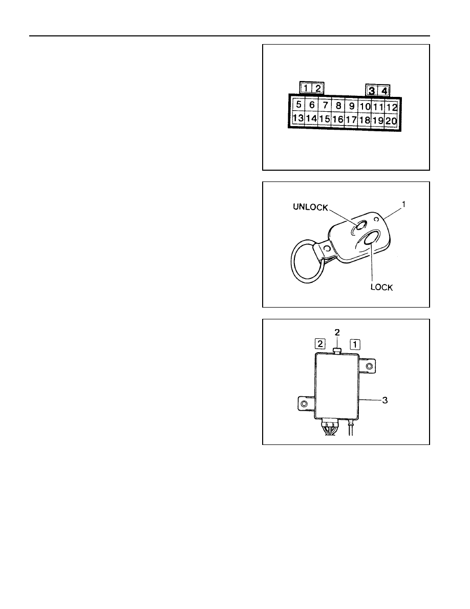
Input Memory

!

When the REKES transmitter is lost

1. Connect the battery terminal No.3 and REKES terminal No.4

which are on the diagnosis socket in engine room with service
lead wire.

2. Push the lock or unlock button on the REKES transmitter.

3. Input Memory and close all doors.

4. Check the operation of door locking system by pushing the

lock or unlock button on the REKES transmitter.

!

When the transmitter is faulty

1. Replace the REKES transmitter with a new one and connect

the wiring connector.

2. Set the input switch of the REKES receiver onto the No.1 or

No.2 position and push the lock or unlock button on the
REKES transmitter.

3. Set the input switch of the REKES receiver onto the central

position and close all doors.

4. Check the operation of door locking system by pushing the

lock or unlock button on the REKES transmitter.

1

REKES Transmitter

2

Input Switch of the REKES Receive

3

REKES Switch

REMOTE KEYLESS ENTRY AND ANTI-THEFT SYSTEM  9T-7

Characteristic Signal

1. Lock or unlock all doors according to the REKES signal

when the key is removed from the key hole.

2. Characteristic Signal : Right Picture

3. Time Interval

T1 : 0.05 ± 0.02sec.(lock signal)

T2 : 0.1 ± 0.02sec.(unlock signal)

T3 : within 0.25sec.

T4 : 0.5 ± 0.1sec.

T5 : within 0.35sec.

T6,T7 : 0.5 ± 0.1sec.

T8 : 1 ± 0.25sec.

Connector Appearance and Connecting Circuit

Pin No.

1

2

3

4

5

6

Connecting Circuit

B+

Memory Terminal

Key Reminder Switch

STICS

Ground

Memory Terminal

SECTION 9U

CONTROL  UNITS  AND  SYSTEM

Caution: Disconnect the negative battery cable before removing or installing any electrical unit or when a
tool or equipment could easily come in contact with exposed electrical terminals. Disconnecting this cable
will help prevent personal injury and damage to the vehicle. The ignition must also be in LOCK unless otherwise
noted.

TABLE OF CONTENTS

Specifications . . . . . . . . . . . . . . . . . . . . . . . .  9U-1

STICS Specifications . . . . . . . . . . . . . . . . . . .  9U-1

Schematic and Routing Diagrams . . . . . . . .  9U-2

STICS . . . . . . . . . . . . . . . . . . . . . . . . . . . . . . .  9U-2

Function Description . . . . . . . . . . . . . . . . . .  9U-3

SPECIFICATIONS

STICS SPECIFICATIONS

Description

DC 12V

Dc 9V - 16V

Less than 1mA(key is removed and all doors locked)

-30

°

C - +80

°

C

Between terminal No.5 and 3,4,8,12,18,25

Between terminal No. 5 and 2,6,7,16,17

Between terminal No.5 and 11, 27

Application

Voltage Rating

Voltage Rating

Current Consumption

Operating Temperature

Voltage Drop

(at DC 12V)

Max. 1.2V

Max. 1.8V

Max. 2.0V

STICS . . . . . . . . . . . . . . . . . . . . . . . . . . . . . . .  9U-3

Maintenance and Repair . . . . . . . . . . . . . .  9U-10

On-Vehicle Service . . . . . . . . . . . . . . . . . . . . .  9U-10

STICS . . . . . . . . . . . . . . . . . . . . . . . . . . . . . .  9U-10

9U-2  CONTROL UNITS AND SYSTEM

STICS

SCHEMATIC  AND ROUTING DIAGRAMS


Content   ..  32  33  34  35   ..