Scania 6000 Instrumentation en-GB 2 268 512. Operator's manual - part 3
Application modes
Application mode {1oc}
Application mode {1oc} has the following functions:
• Measurement of engine parameters, and generator
parameters, i.e., voltage, frequency, current, power,
coolant temperature, oil pressure, etc.
• Starting or stopping the engine.
• Engine protection and generator protection in the
form of relay output in the opening of generator set
circuit breakers.
• Relay output for the closure of the generator set cir-
cuit breaker.
• Detection of power failure on normal electrical pow-
er network,
Application mode {2oc}
Application mode {2oc} has the following functions:
• Measurement of engine parameters, and generator
parameters, i.e., voltage, frequency, current, power,
coolant temperature, oil pressure, etc.
• Starting or stopping the engine.
• Engine protection and generator protection in the
form of relay output in the opening of generator set
circuit breakers.
• Relay output for the closure of the generator set cir-
cuit breaker.
• Relay output for opening and closing of the circuit
breaker in the automatic transfer switch.
• Detection of power failure on normal electrical pow-
er network and automatic startup and shutdown of
the engine.
32
Operating modes
Operating modes
Operating mode stop
Note:
Operating mode stop is not the same as an emergency stop. In
some cases the instrument panel carries out additional logic func-
tions, such as an engine cooling-off period before the engine is
turned off. Scania recommends that a digital input for emergency
stop is used and programmed as an alarm of class F.
In the operating mode stop neither the engine or generator set cir-
cuit breakers run. Depending on the application mode, the circuit
breakers cannot be operated.
The following occurs if operating mode stop is se-
lected when the engine is already shut down:
• Generator set circuit breaker does not close.
• The fuel solenoid relay is not activated.
• Commands for the digital inputs and CAN bus are ignored.
• Display buttons for start disabled, depending on previous op-
erating mode.
• The monitoring of the generator set remains disabled, except
for the monitoring that is not dependent on engine speed.
33
Operating modes
The following occurs if the operating mode stop
has been selected when the engine is running
• The circuit breaker in the generator set opens when
- the instrument panel is at least in application mode {1o}
- the circuit breaker in the generator set is closed.
• The circuit breaker in the automatic transfer switch closes
when
- the instrument panel is at least in application mode {2oc}
- the circuit breaker in the generator set is open
- the circuit breaker in the automatic transfer switch is acti-
vated
- the parameter close MCB in stop mode (close the circuit
breaker in the automatic transfer switch in operating mode
stop) is set to YES.
• Engine cooling is performed and the indicator lamp for oper-
ating mode stop flashes.
• The fuel solenoid relay is deactivated.
• The monitoring of the generator set is disabled, except for the
monitoring that is not dependent on engine speed.
• The instrument panel display displays the steps when they are
carried out.
The following occurs if the operating mode stop
has been selected when the engine implements
cooling.
• The cooling is stopped and the engine is turned off.
Note:
If the logic handler function Enable MCB (the circuit breaker in
the automatic transfer switch) (parameter 12923) has the value
true, the circuit breaker in the automatic transfer switch closes
again if it is open in the operating mode stop.
34

Operating modes
Manual operating mode
In manual operating mode, the engine and the circuit breakers are
operated via the display buttons at the bottom of the view.
Any device that can be operated via the display button has a black
border, others may not be operated. The line diagrams's lowest
line changes according to the application mode.
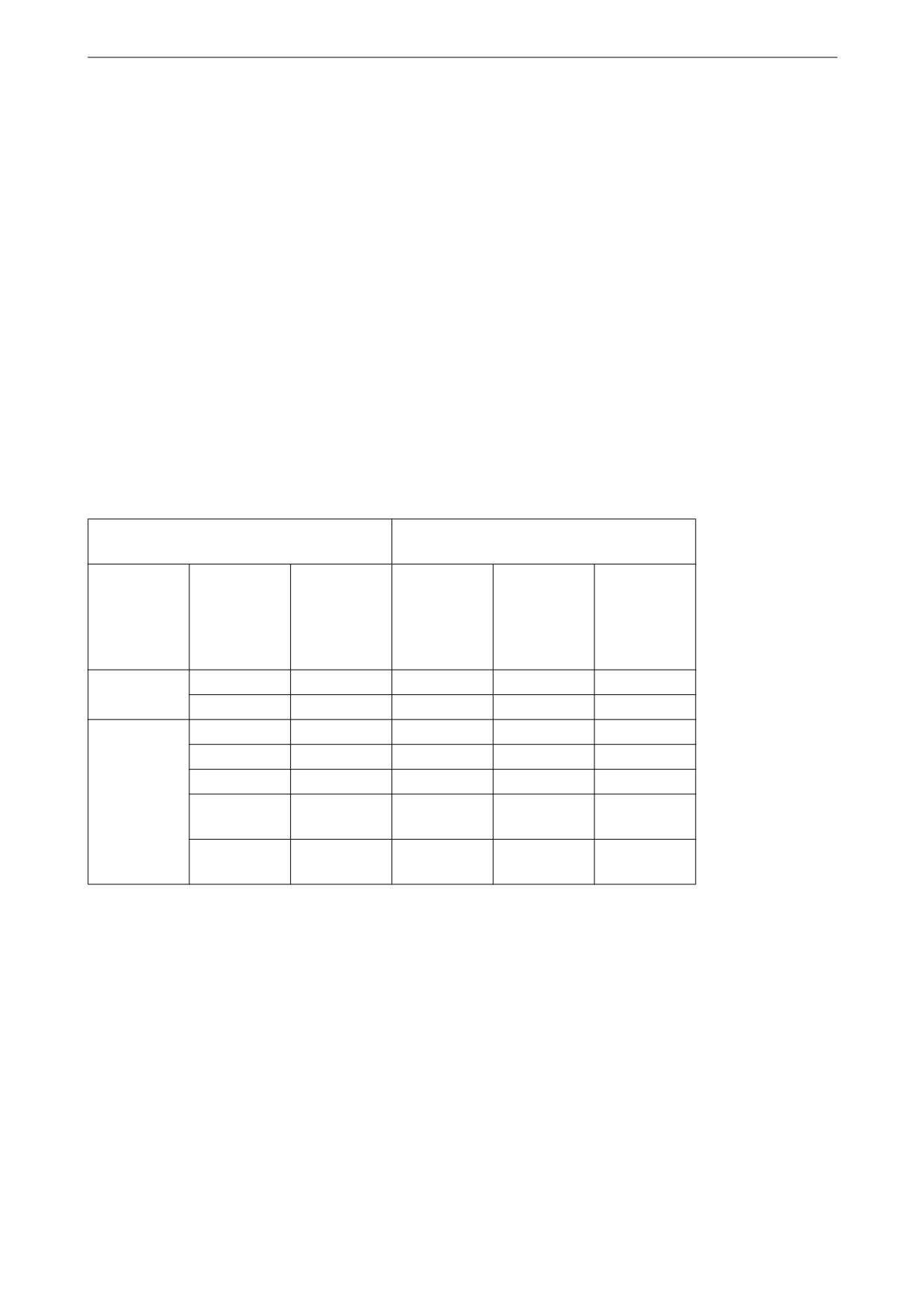
Line diagram for application mode {0}
For application mode {0} a display button with a black frame is
displayed around the engine to indicate that it is possible to start
and stop the engine.
Example of line diagram
• Start the engine
• Shut off the engine
Line diagram for application mode {1o}
For application mode {1o} display buttons for both the engine
and generator set power circuit breaker are displayed with the fol-
lowing functions.
The symbol X indicates that an open command for the circuit
breaker has been issued and the closing of the circuit breaker has
been blocked. The dotted line indicates no defined status of the
circuit breaker.
Example of line diagram
• Start the engine
• Shut off the engine
• Open the circuit breaker in
the generator set
35
Operating modes
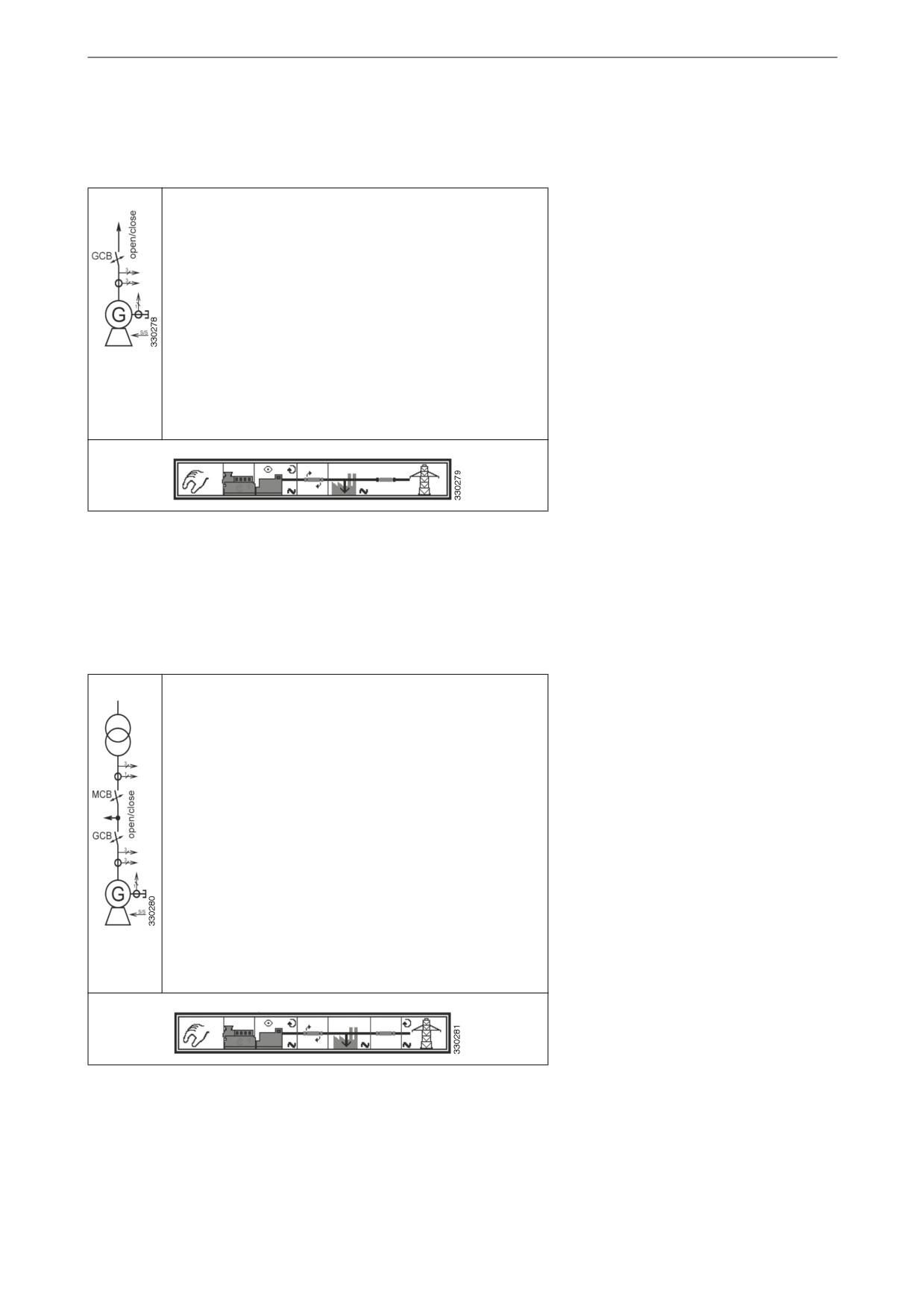
Line diagram for application mode {1oc}
For application mode {1oc} display buttons for both the engine
and generator set power circuit breaker are displayed with the fol-
lowing functions.
Example of line diagram
• Start the engine
• Shut off the engine
• Open the circuit breaker in
the generator set
• Close the circuit breaker in
the generator set
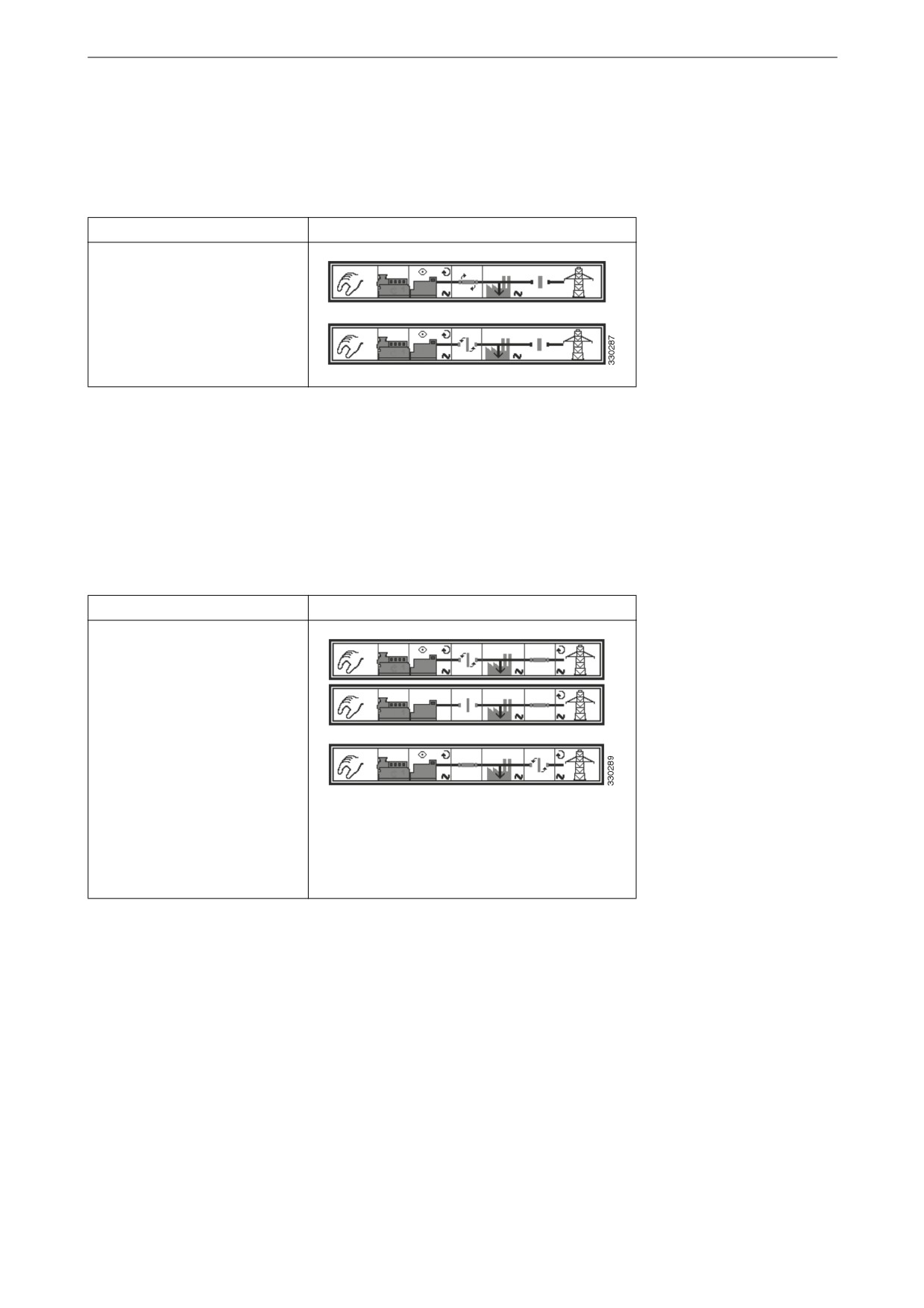
Line diagram for application mode {2oc}
For application mode {2oc} display buttons for the engine, the
circuit breaker in the generator set and the circuit breaker in the
automatic transfer switch are displayed with the following func-
tions:
Example of line diagram
• Start the engine
• Shut off the engine
• Open the circuit breaker in
the generator set
• Close the circuit breaker in
the generator set
• Open the circuit breaker in
the automatic transfer
switch
• Close the circuit breaker in
the automatic transfer
switch
36
Operating modes
Automatic operating mode
In automatic operating mode, all functions of the motor, circuit
breakers in generator sets and automatic transfer switches are op-
erated via a remote start signal, or automatically by the instru-
ment panel, such as during a power failure on the normal
electrical power network.
The function of the instrument panel depends on its configuration
and the external signals used.
The main features are briefly described as follows.
Starting the engine
Remote engine start
The engine is started with a remote start signal.
A remote start requires that:
• Automatic operating mode is enabled.
• The Start req. in AUTO function is assigned to a digital input
via the logic handler and the conditions are met (true).
• The digital input or an external start is activated (logic high
signal ) or the necessary command interface is set on the inter-
face.
• An alarm of class C or higher is not present.
• The engine is ready for operation.
• Generator set circuit breaker is open.
37
Operating modes
Power failure
Automatic operation during a power failure on the normal elec-
trical power network.
If the automatic operating mode is enabled, the application mode
is {2oc} and a power failure on the normal electrical power net-
work is detected, the engine and the circuit breakers are operated
in accordance with the conditions in the table below.
An automatic start require that:
• Automatic operating mode is enabled.
• Application Mode is configured as {2oc}.
• The Emergency power parameter is configured.
• The configured limits for power failure on the normal electri-
cal power network is reached.
• The configured delay times have expired.
• An alarm of class C or higher is not present.
• The engine is ready for operation.
Status before detected power failure on
Measure in order
the normal electrical power network
Engine
Circuit
Circuit
Engine
Circuit
Circuit
breaker in
breaker in
breaker in
breaker in
the genera-
the auto-
the genera-
the auto-
tor set
matic trans-
tor set
matic trans-
fer switch
fer switch
0 (switched
0 (opened)
0 (opened)
1 (start)
2 (closes)
off)
0 (opened)
1 (closed)
1 (start)
3 (closes)
2 (opens)
1 (running)
0 (opened)
0 (opened)
--
1 (closes)
0 (opened)
1 (closed)
--
2 (closes)
1 (opens)
1 (closed)
0 (opened)
--
--
--
1 (closed)
1 (closed)
--
1 (opens)3
2 (closes)
(closes)
1 (closed)
1 (closed)
--
(remains
1 (opens)
closed)
38
Components in the central electric unit
Components in the central electric
unit
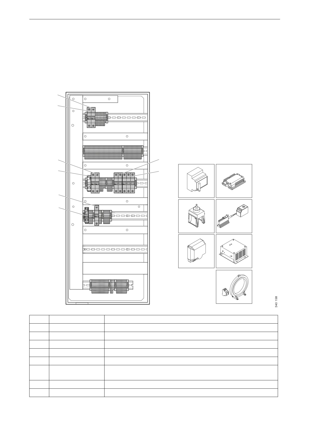
The illustration below shows the location of the components in-
side the central electric unit. The figure shows all options, and the
central electric unit ordered can therefore have other equipment.
1
2
3
7
9
10
4
8
5
11
12
6
13
14
15
Pos.
Designation
Description
1
MCB2
Miniature circuit breaker for instrument panel, 10 A
2
MCB1
Miniature circuit breaker for engine control unit, 20 A
3
MCB3
Miniature circuit breaker for coolant heater, 10 A
4
MCB6
Miniature circuit breaker for battery charger, 6 A
5
MCB4
Miniature circuit breaker for instrument panel heating element, 2 A
6
HCR
Relay for engine heater, instrument panel heater element and generator
heater
7
MCB
Miniature circuit breakers for load voltage
8
MCB
Miniature circuit breakers for mains voltage
39

Components in the central electric unit
Pos.
Designation
Description
9
Netbiter WS200
Communication unit for remote connection
10
Expansion unit
16 additional inputs and outputs
11
Switch
For changing between 50/60 Hz
12
OH2/FLZ510
Heater element for instrument panel/thermostat
13
Battery charger
For 110 V electrical power network
14
Battery charger
For 220/240 V electrical power network
15
Hobut
Residual current device
40