Scania 6000 Instrumentation en-GB 2 268 512. Operator's manual - part 2

Display navigation
Measured values
This view is displayed when the display button Measured values
in the view Next page is pressed.
Return to view Next page.
J1939 interface
Display view for J1939 interface.
Analog inputs/
Display view for analogue inputs and outputs.
outputs
Discrete inputs/
Display view for digital inputs and outputs.
outputs
Generator
Display view for generator.
Busbar
Display view for busbar.
Mains
Display view for normal electrical power net-
Measured values
work.
Note:
Digital inputs and outputs are designated as Discrete inputs/out-
puts on the display button and in views.
J1939 interface
This view is displayed when the display button J1939 interface in
the Measured values view is pressed. Values that have been trans-
mitted from the engine control unit are shown here. If a value is
not transmitted, Missing is displayed.
Return to view Measured values.
Scroll up in the view
J1939 interface
Scroll down in the view
16
Display navigation
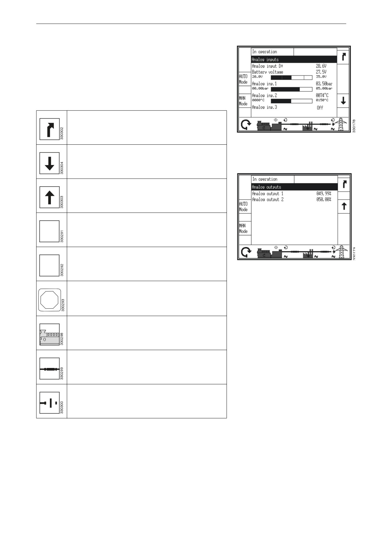
Analogue inputs and outputs
This view is displayed when the display button Analog inputs/
outputs in the Measured values view is pressed.
The analogue outputs are displayed as a percentage of the select-
ed hardware range, i.e. 50% on a 0-20 mA output refers to 10 mA.
Return to view Measured values.
Analogue inputs
Scroll down to the view for analogue outputs.
Scroll up to the view for analogue inputs.
Switch to automatic operating mode.
"650
.PEF
Switch to manual operating mode.
."/
Analogue outputs
.PEF
Switch to operating mode stop.
4501
Start or switch off the engine. Only displayed in manual
operating mode.
Open circuit breaker in the generator set or in the auto-
matic transfer switch. Only displayed in manual operat-
ing mode.
Close circuit breaker in the generator set or in the auto-
matic transfer switch. Only displayed in manual operat-
ing mode.
17

Display navigation
Digital inputs and outputs
This view is displayed when the display button Discrete inputs/
outputs in the Measured values view is pressed.
The status of digital inputs and outputs is displayed.
Note:
Digital inputs and outputs are designated as Discrete inputs/out-
puts on the display button and in views.
Internal digital inputs and outputs
Return to view Measured values.
Scroll down to view for external digital inputs and out-
puts.
Scroll up to view for internal digital inputs and outputs.
Switch to automatic operating mode.
"650
.PEF
Switch to manual operating mode.
."/
.PEF
External digital inputs and outputs
Switch to operating mode stop.
4501
Start or switch off the engine. Only displayed in manual
operating mode.
Open circuit breaker in the generator set or in the auto-
matic transfer switch. Only displayed in manual operat-
ing mode.
Close circuit breaker in the generator set or in the auto-
matic transfer switch. Only displayed in manual operat-
ing mode.
18

Display navigation
Status of digital inputs and outputs is displayed with filled or un-
filled square.
The configuration of the input determines how the instrument
panel reacts. If the input is configured as normally open it will re-
act when it is energised. If the input is configured as normally
closed it will react when it is de-energised. Refer to the table be-
low.
Digital input:
energized.
Main measured values for the generator
de-energized.
Digital output:
activated.
deactivated.
Generator
This view is displayed when the display button Generator in the
Measured values view is pressed.
All measured generator values are displayed in this view.
Return to view Measured values.
Scroll down to the view for additional generator meas-
urements.
Scroll up to the view for main generator measurements.
Reset the maximum measured values.
Switch to automatic operating mode.
"650
.PEF
Additional measured values for the gener-
ator
19
Display navigation
Switch to manual operating mode.
."/
.PEF
Switch to operating mode stop.
4501
Start or switch off the engine. Only displayed in manual
operating mode.
Open circuit breaker in the generator set or in the auto-
matic transfer switch. Only displayed in manual operat-
ing mode.
Close circuit breaker in the generator set or in the auto-
matic transfer switch. Only displayed in manual operat-
ing mode.
V
Voltage.
I
Current.
P
Actual power.
Q
Reactive power.
S
Apparent power.
PF
Power factor.
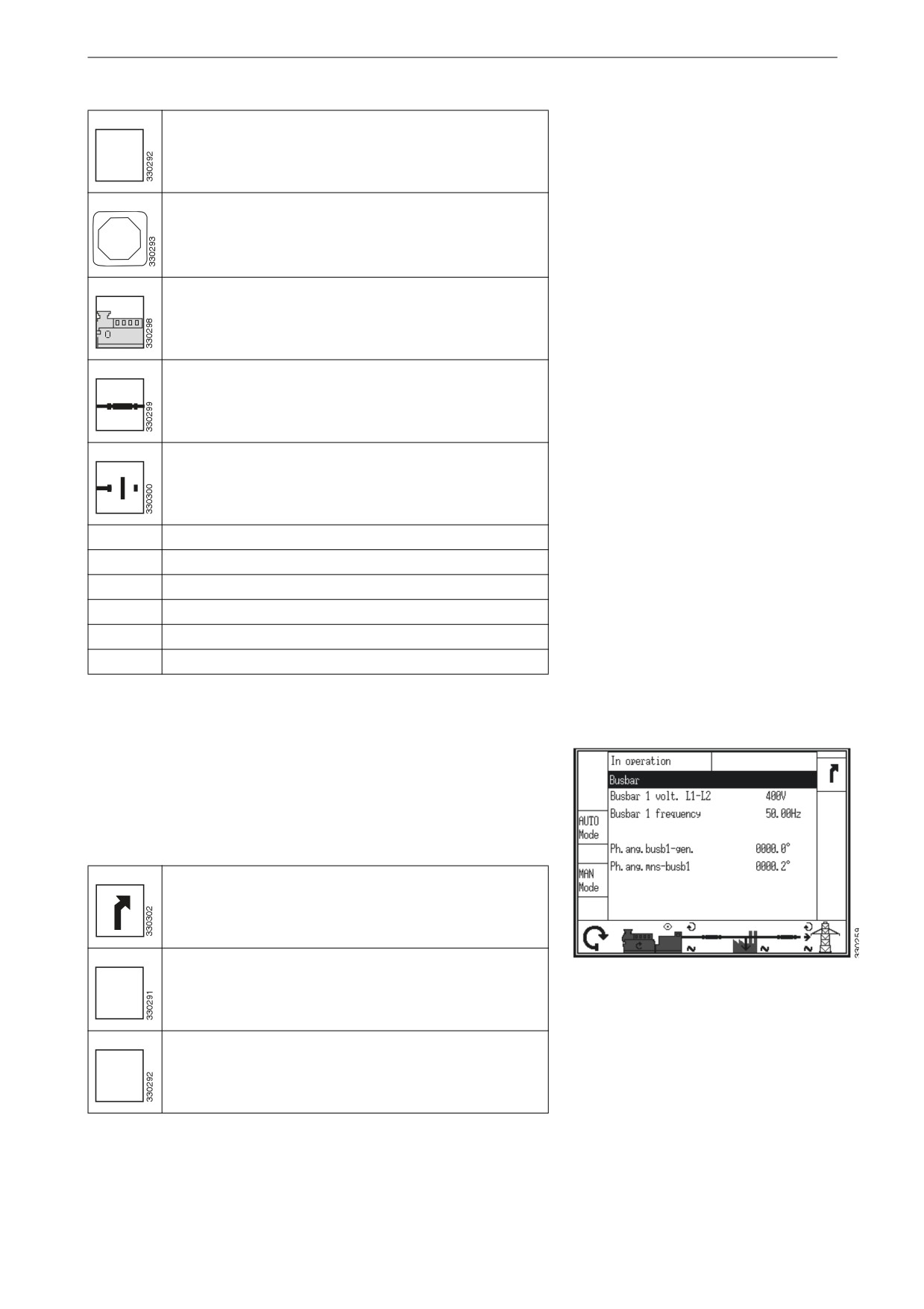
Busbar
This view is displayed when the display button Busbar in the
Measured values view is pressed.
All measured values on the busbar are displayed.
Return to view Measured values.
Switch to automatic operating mode.
Busbar
"650
.PEF
Switch to manual operating mode.
."/
.PEF
20

Display navigation
Switch to operating mode stop.
4501
Start or switch off the engine. Only displayed in manual
operating mode.
Open circuit breaker in the generator set or in the auto-
matic transfer switch. Only displayed in manual operat-
ing mode.
Close circuit breaker in the generator set or in the auto-
matic transfer switch. Only displayed in manual operat-
ing mode.
Electrical power network
This view is displayed when the display button Mains in the
Measured values view is pressed.
All measured values for the electrical power network are dis-
played.
Return to view Measured values.
Scroll down to the view for additional network meas-
urements.
Main measured values for the electrical
power network
Scroll up to the view for main network measurements.
Reset the maximum measured values.
Switch to automatic operating mode.
"650
.PEF
Switch to manual operating mode.
."/
.PEF
Additional measured values for the elec-
trical power network
21

Display navigation
Switch to operating mode stop.
4501
Start or switch off the engine. Only displayed in manual
operating mode.
Open circuit breaker in the generator set or in the auto-
matic transfer switch. Only displayed in manual operat-
ing mode.
Close circuit breaker in the generator set or in the auto-
matic transfer switch. Only displayed in manual operat-
ing mode.
V
Voltage.
I
Current.
P
Actual power.
Q
Reactive power.
S
Apparent power.
PF
Power factor.
22

Display navigation
Diagnostics
This view is displayed when the display button Diagnostic in the
Next page view is pressed.
Diagnostics
Return to view Next page.
LogicsManager
Display the view for handling of the com-
conditions
mand variables.
Actual date and
Display the view for current date and time.
time
Event history
Display view for event history. Requires pass-
word for access.
Version
Display view for version. Requires password
for access.
23

Display navigation
Command variables
This view is displayed when the display button Logics Manager
conditions in the Diagnostic view is pressed.
The status is displayed for all variables, divided into groups in the
system.
Return to view Diagnostic.
Variable groups
Scroll up a group or variable.
Scroll down a group or variable.
Select the highlighted variable group and view the sta-
tus of variables in this group.
Status for variables is displayed with a filled or unfilled square.
Variable values for group 4 (example)
True.
False.
24
Display navigation
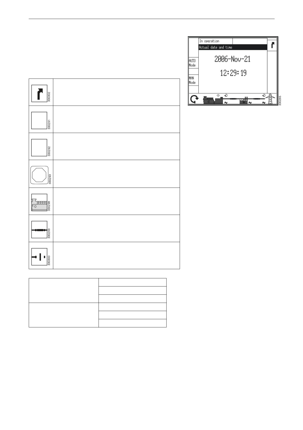
Current date and time
This view is displayed when the display button Actual date and
time in the Diagnostic view is pressed.
Current date and time is displayed.
Return to view Diagnostic.
Switch to automatic operating mode.
Current date and time
"650
.PEF
Switch to manual operating mode.
."/
.PEF
Switch to operating mode stop.
4501
Start or switch off the engine. Only displayed in manual
operating mode.
Open circuit breaker in the generator set or in the auto-
matic transfer switch. Only displayed in manual operat-
ing mode.
Close circuit breaker in the generator set or in the auto-
matic transfer switch. Only displayed in manual operat-
ing mode.
xxxx = Year.
Date. xxxx-yyy-zz
yyy = Month.
zz = Day.
xx = Hour.
Time. xx:yy:zz
yy = Minute.
zz = Second.
25
Operation
Operation
A
B
Display
The display is divided into sub views.
C
F
E
D
A = Operating mode
B = Alarm messages
C = Measurements
D = Operation
E = Display buttons
F = Display buttons
Operating mode
Sub view Operating mode displays actual operating information.
A
B
C
F
E
D
Operating mode
Alarm messages
The alarm messages sub view displays the last alarm message
that is not yet confirmed.
A
B
C
F
E
D
Alarm messages
26
Operation
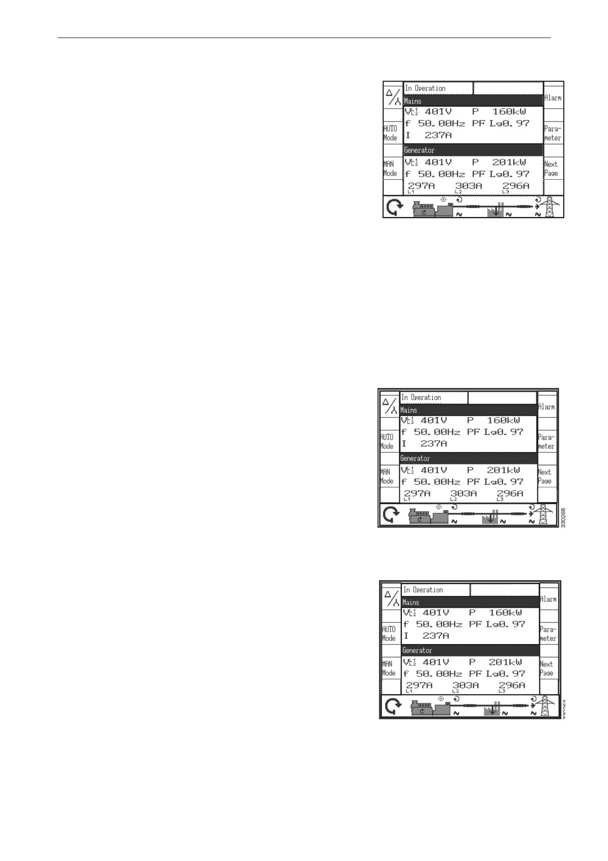
Measured values
A
B
The measurement sub view displays all the measured power-re-
lated information including voltages, currents, frequencies, pow-
er and power factor values.
C
F
E
D
Measured values
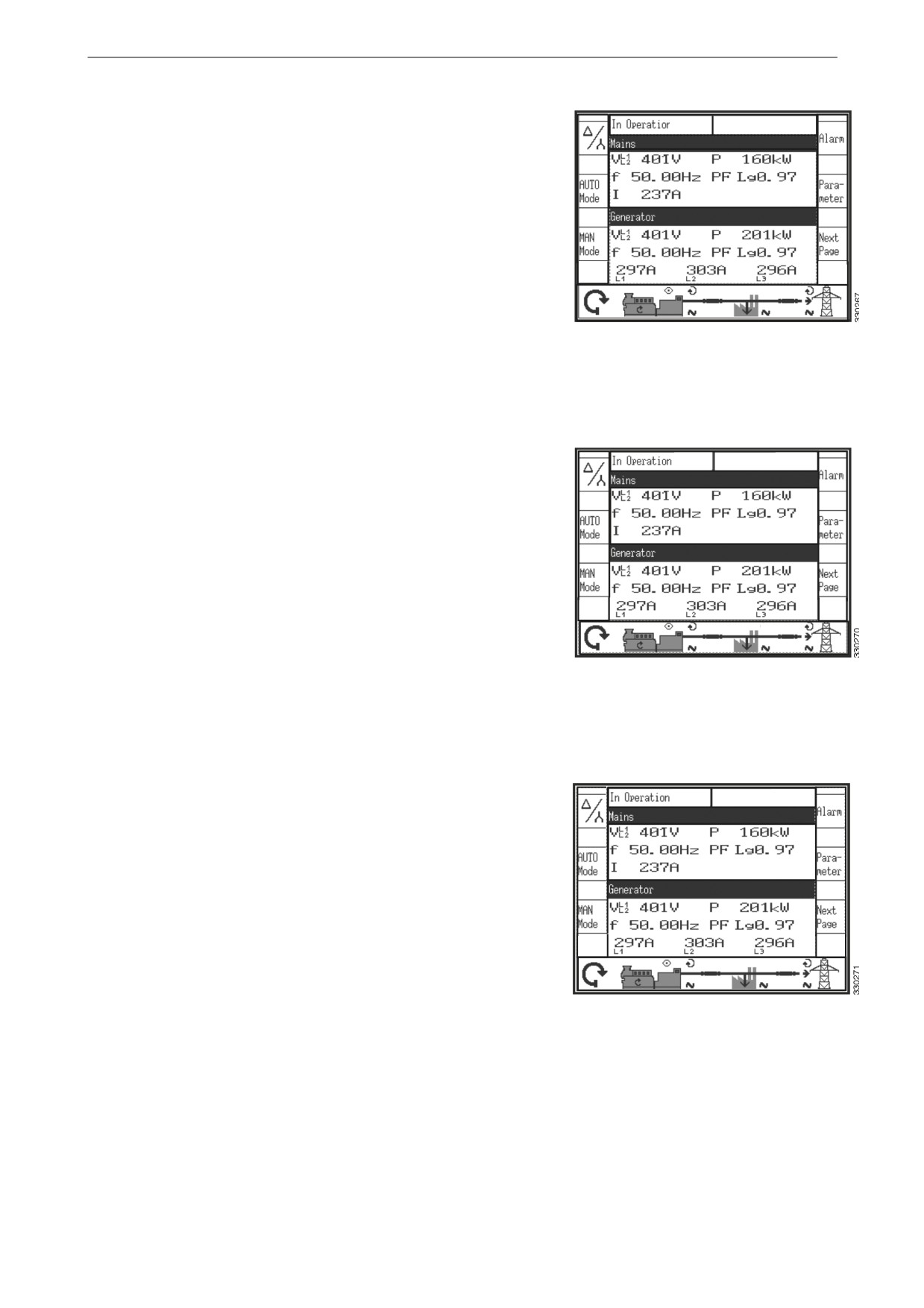
Operation
The Operation sub view has a line diagram of the system applica-
A
B
tion that displays the current status of the engine and circuit
breakers.
This sub view displays the buttons for manual operation of the
C
generator set.
F
E
D
Operation
Display buttons
A
B
The sub view Display buttons allow navigation between views,
levels and functions as well as configuration and operation.
C
F
E
D
Display buttons
27

Operation
Choice of operating modes
By pressing the display buttons AUTO Mode, MAN Mode or
STOP the desired operating mode is selected.
Depending on the selected application mode various display but-
tons on the display are turned on or off . The active operation
mode is displayed to the left of the engine symbol.
A
B
If the operating mode stop is selected, the indicator lamp next to
the push-button illuminates and operation mode is displayed to
the left of the engine symbol.
C
Note:
If the instrument panel is configured for the external selection of
operating mode, the display buttons for the automatic and manual
F
E
operating mode are not displayed and the pushbutton for the op-
D
erating mode stop is disabled. The operating mode cannot be
changed.
Display buttons for selecting operating
mode
Automatic operating mode, AUTO Mode. When auto-
matic operating mode is selected, the instrument panel
"650
performs the startup and shutdown of the engine as well
.PEF
as closing and opening of circuit breakers. The func-
tions are performed according to how the instrument
panel is configured.
Automatic operating mode is indicated by the symbol in
the lower left corner of the view.
Manual operating mode, MAN Mode. When manual
operating mode is selected, the engine is started and
."/
stopped and circuit breakers closed and opened manual-
.PEF
ly using display buttons at the bottom of the view.
Manual operating mode is indicated by the symbol in
the lower left corner of the view.
When the operating mode stop is selected, the engine
switches off.
STOP
Operating mode stop is indicated by the symbol in the
lower left corner of the view.
4501
28

Operation
Operation
Display buttons in manual operating mode
When manual operating mode is selected, the display buttons are
enabled for manual operation of the engine and circuit breakers.
The symbols 0 and 1 indicate if a start command or a stop com-
mand is being processed currently.
The arrows on the circuit breaker symbols indicate if an open
command or a close command is being processed currently.
A
B
The eye symbol indicates that the engine control functions are en-
abled. The network symbol indicates that there is voltage on each
unit: generator, busbar or normal electrical power network.
C
The direction of the circular arrow indicates whether the phase
rotation field of the generator or the normal electrical power net-
work is clockwise or anti-clockwise.
The arrow symbol at the normal electrical power network con-
F
E
nection point indicates whether the power is exported or import-
D
ed.
Display buttons in manual operating
mode
Start or switch off the engine.
Press the display button to start the engine.
• If the engine starts, the circular arrow indicates the
engine is running. The eye symbol indicates that the
monitoring functions are enabled.
• If the engine fails to start, the message for failed
start is displayed.
Press the display button to switch off the engine.
• When the engine is switched off the circular arrow
and the eye symbol disappear.
• If the engine fails to shut down, the message for
failed shutdown is displayed.
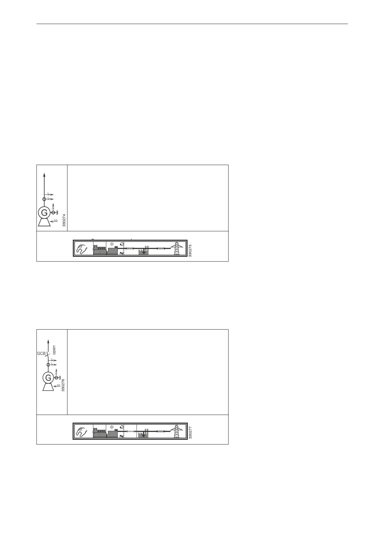
Close or open the circuit breaker in the generator set
or in the automatic transfer switch
Press the display button below the desired circuit
breaker when the symbol is vertical to close it.
• If the circuit breaker closes, the icon changes to a
horizontal position.
• If the circuit breaker fails to close the symbol
remains in a vertical position.
29

Operation
Press the display button below the desired circuit
breaker when the symbol is horizontal to open it.
• If the circuit breaker opens, the icon changes to a
vertical position.
• If the circuit breaker fails to open the symbol
remains in a horizontal position.
30
Application modes
Application modes
The application mode can only be changed during configuration
with the authorisation level CL2 or higher.
The main characteristics of the four application modes are dis-
played in the following section.
Application mode {0}
Application mode {0} has the following functions:
• Measurement of engine parameters, and generator
parameters, i.e., voltage, frequency, current, power,
coolant temperature, oil pressure, etc.
• Starting or stopping the engine.
Application mode {1o}
Application mode {1o} has the following functions:
• Measurement of engine parameters, and generator
parameters, i.e., voltage, frequency, current, power,
coolant temperature, oil pressure, etc.
• Starting or stopping the engine.
• Engine protection and generator protection in the
form of relay output in the opening of generator set
circuit breakers.
• Detection of power failure on normal electrical pow-
er network,
31