Scania 6000 Instrumentation en-GB 2 268 512. Operator's manual - part 1
Operator's manual
6000
Instrumentation
en-GB 2 268 512
Issue 1.0
Preface
3
Functions
3
Instrument panel
5
Display navigation
6
Overview of operating values in the home view
6
Alarm messages
7
Next page
8
Setting values
8
Synchroscope
10
Load sharing
13
Counter and inspection
14
Measured values
16
Diagnostics
23
Operation
26
Display
26
Choice of operating modes
28
Operation
29
Application modes
31
Application mode {0}
31
Application mode {1o}
31
Application mode {1oc}
32
Application mode {2oc}
32
Operating modes
33
Operating mode stop
33
Manual operating mode
35
Automatic operating mode
37
Components in the central electric unit
39
2
Preface
Preface
This Operator’s manual describes operation of instrument panel
6000. The information was correct at the time of going to press.
Scania reserves the right to make alterations without prior notice.
Note:
This Operator’s manual describes a generator set that is equipped
with all available options. Ignore inputs and outputs, functions,
views and other details not found on your generator set.
This Operator’s manual is for guidance only; this is because the
large number of parameter settings does not make it possible to
describe every possible combination.
Note:
Always use Scania spare parts for repair work.
Functions
Instrument panel 6000 is a microcontroller-based instrument
panel used to start and stop the generator set manually or auto-
matically via an external signal.
The instrument panel runs and monitors parameters to ensure
trouble-free operation of the generator set. The instrument panel
display displays the operational status and display messages.
Instrument panel 6000 has the following functions:
• Operates the generator set.
• Protects the engine, generator and electrical power network.
• Measures engine data: oil pressure and temperature, coolant
temperature, battery voltage, rotational speed, inspection etc.
• Measures electrical power network and generator data: volt-
age, current, power, etc.
• Performs load balancing for up to 32 input generator sets.
• Performs load dependent start/stop.
•
3 operating modes: automatic operating mode, manual oper-
ating mode and operating mode stop.
• Application modes:
- starts and stops the engine, no operation of circuit breakers
- opens the circuit breaker in the generator set
- opens and closes the circuit breaker in the generator set
- opens and closes the circuit breaker in the generator set and
the circuit breaker in the automatic transfer switch (ATS).
• Handles readings, digital inputs and internal states.
• Starts the engine.
• Displays alarms, trips the miniature circuit breakers and
switches off the engine.
3
Functions
• With the generator set in standby mode: starts the generator
set automatically upon detection of a power failure on the nor-
mal electrical power network.
• Performs operation in critical condition.
• Performs synchronization on normal electrical power network
in parallel operation.
• Performs external control of frequency, voltage, power and
power factor via analogue input or interface.
• Displays event history with 300 entries.
• Multilingual user interface.
• Retrieves data from the engine control unit via J1939 for di-
agnostics and forecasting.
• Communicates via CAN with the engine control unit, facility
management system, expansion card and ToolKit program-
ming tool.
• Communicates with facility management system via RS-485
Modbus.
• Communicates with facility management system via RS-232
Modbus.
4
Instrument panel
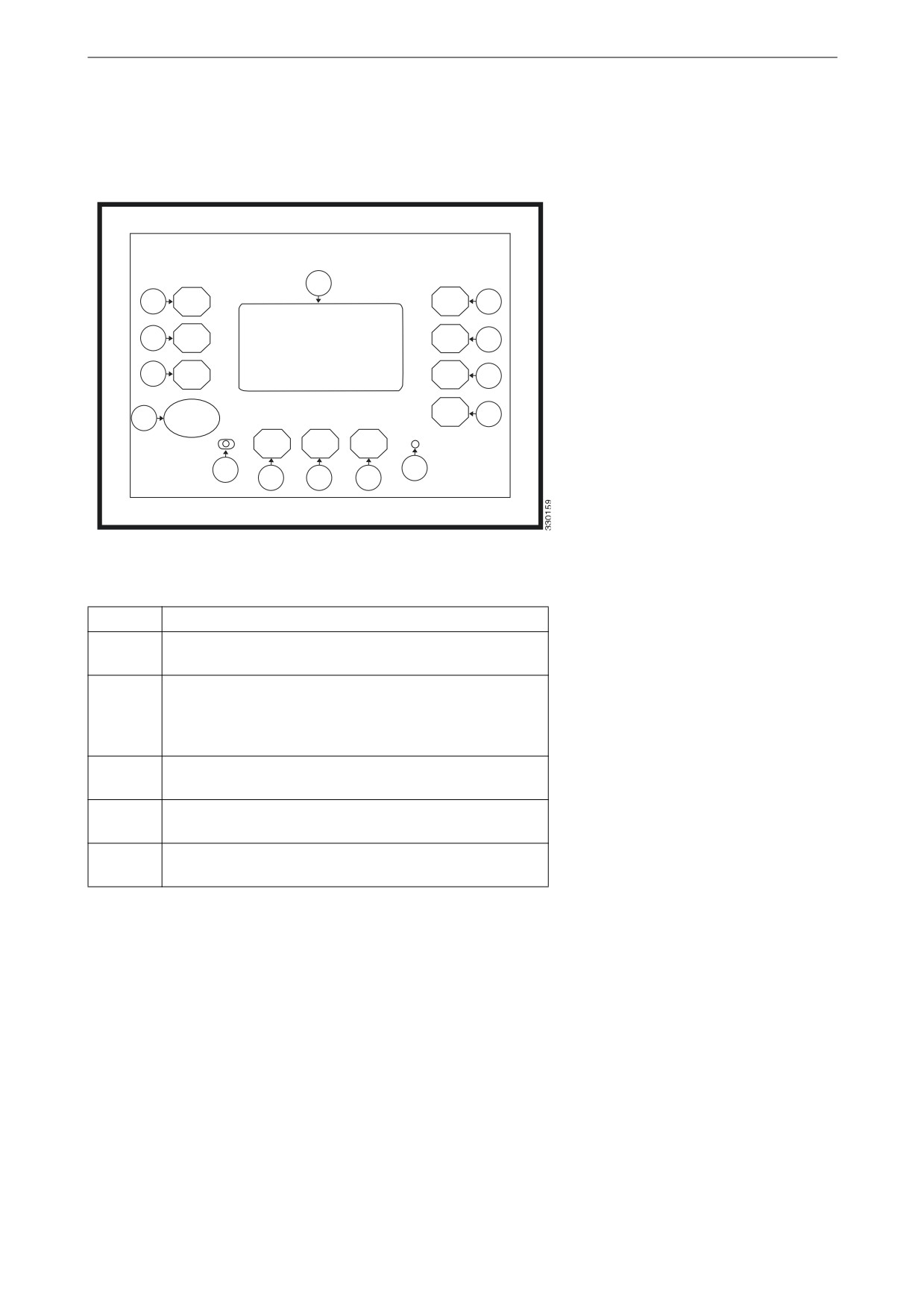
Instrument panel
The illustration below displays the instrument panel with switch-
es, indicator lamps and display.
12
1
5
2
6
3
7
4
STOP
8
13
14
9
10
11
Item
Function
1-3 and
Display buttons with functions dependent on the oper-
5-11
ating mode selected.
4
When pressed the STOP switch switches off the gener-
ator set engine. When the operating mode is selected
externally, the switch STOP, the display buttons
AUTO Mode and MAN mode are deactivated.
12
The display includes display button and displays meas-
urement values, operating mode and alarm messages.
13
The left-hand indicator lamp indicates that the instru-
ment panel is in operating mode stop.
14
The right-hand indicator lamp indicates that there are
alarm messages in the instrument panel.
5

Display navigation
Display navigation
The information content comprises different views.
The display buttons that are available in each view are described
below.
Overview of operating values in the
home view
This view is displayed on starting and you can choose between
different operating modes.
Switch between display of voltage phase to phase or
phase to neutral conductor. The index on the V-symbol
indicates what is displayed.
Operating mode stop
Switch to automatic operating mode.
"650
.PEF
Switch to manual operating mode.
."/
.PEF
Switch to operating mode stop.
4501
Display unacknowledged alarm messages.
Automatic operating mode
"MBSN
Display configuration view. Requires password for ac-
1BSB
cess.
NFUFS
Display view Next page with choice for further infor-
/FYU
mation.
1BHF
Acknowledge alarm messages and stop the alarm sig-
nal. Displayed only if the warning lamp 14 is flashing.
Start or switch off the engine. Only displayed in man-
Manual operating mode
ual operating mode.
6
Display navigation
Open circuit breaker in the generator set or in the auto-
matic transfer switch. Only displayed in manual oper-
ating mode.
Close circuit breaker in the generator set or in the auto-
matic transfer switch. Only displayed in manual oper-
ating mode.
Note:
If the data view for the electrical power network is disabled, the
above view displays only generator set data with larger numbers.
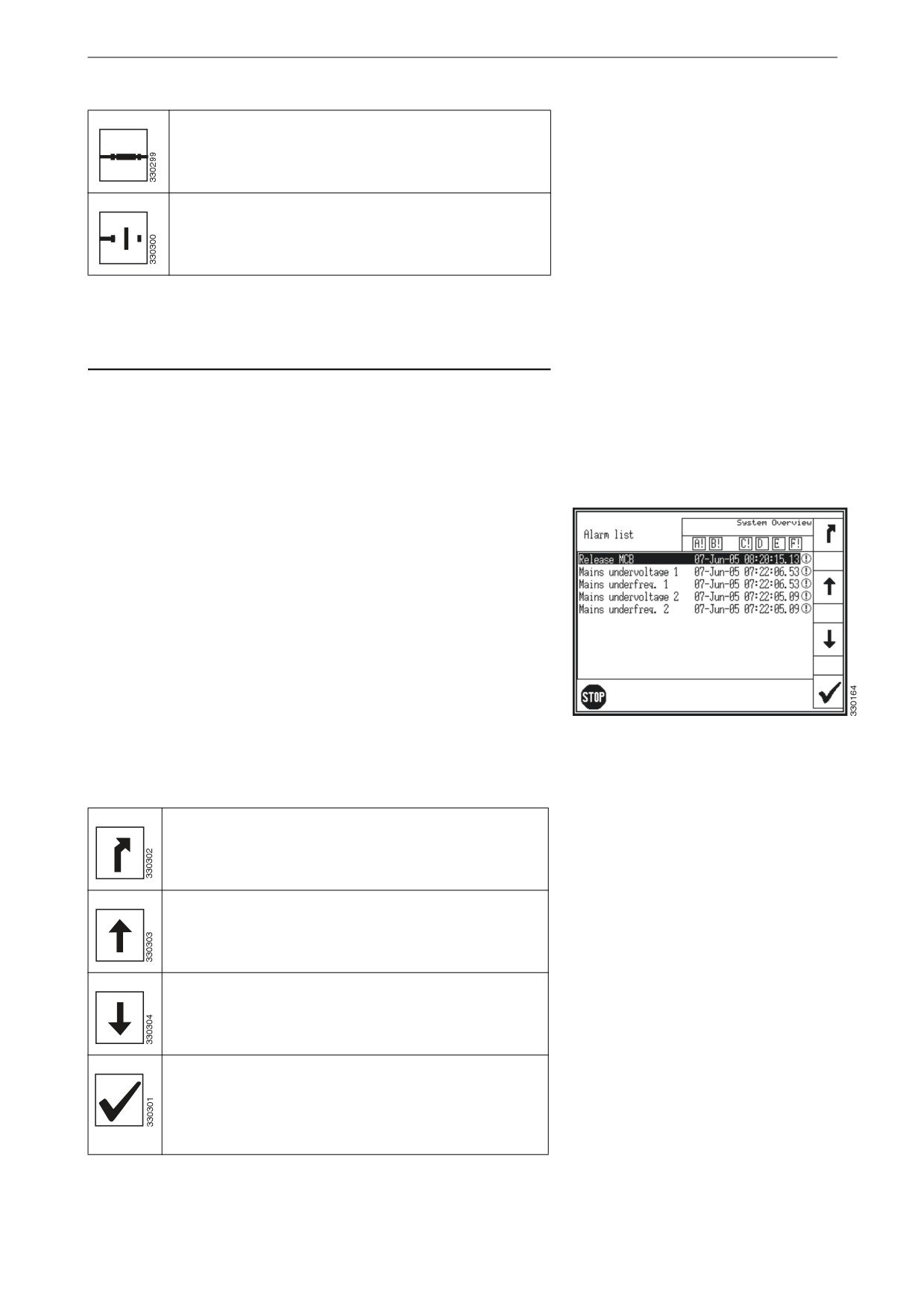
Alarm messages
The view Alarm List is displayed when the display button Alarm
on the home view is pressed. All alarm messages that have not
been acknowledged are displayed.
Each alarm message is displayed with date and time for the alarm
in the format year-month-day-hour-minute-second-hundredth of
a second.
Self-acknowledging alarm messages get a new time stamp when
the unit is started. The symbol with the exclamation mark at the
far right indicates that the cause of the current alarm persists.
A maximum 16 alarm messages can be displayed. If additional
alarm notification occurs, these are displayed only when already
displayed alarm messages have been acknowledged.. The symbol
Alarm messages
with the exclamation mark following the letters A to F, indicates
whether the corresponding alarm class is present or not.
Return to the Home view.
Scroll up to the next alarm message.
Scroll down to the next alarm message.
Acknowledge the selected alarm message (inverted
display). This is possible only if the cause of the alarm
is no longer present. If the cause of an alarm persists
and the indicator lamp of an alarm flashes, the alarm
signal stops and the alarm is marked as confirmed.
7
Display navigation
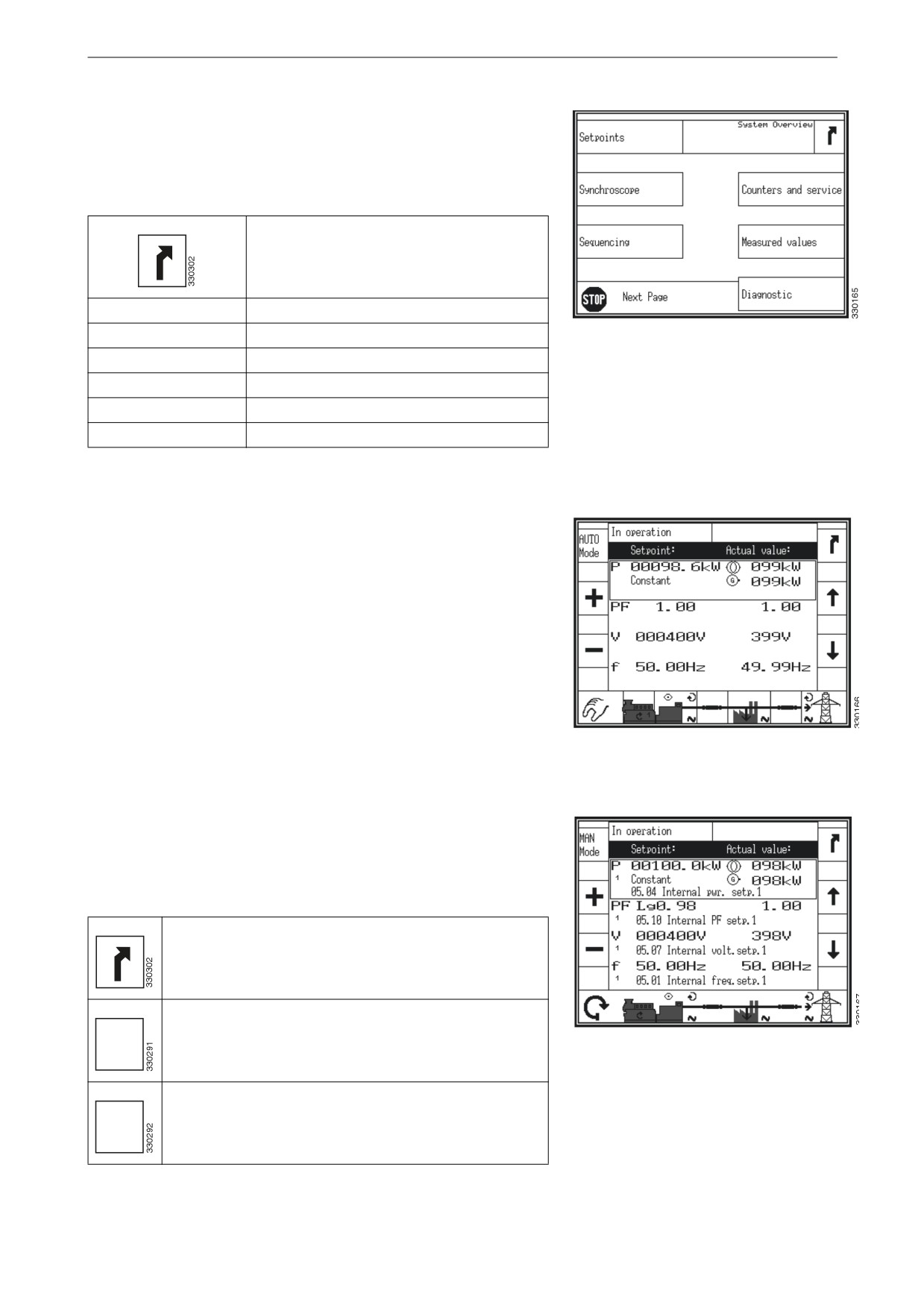
Next page
This view is displayed when the display button Next Page on the
home view is pressed.
Return to the Home view.
Setpoints
Display view for set values.
Synchroskope
Display view of synchroscope.
Next page
Sequencing
Display view for load distribution.
Counters and service
Display view for counter and inspection.
Measured values
Display view for measurement values.
Diagnostic
Display view for diagnostics.
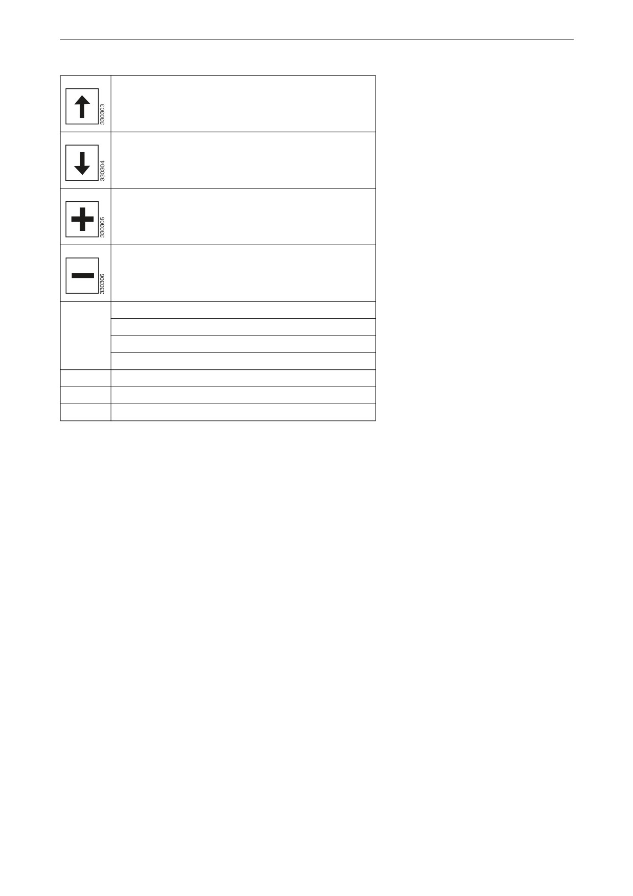
Setting values
This view is displayed when the display button Setpoints in the
Next page view is pressed.
The setting value is displayed on the left half and the actual value
on the right half of the view.
Two symbols indicate electrical power network output and gen-
erator output.
The numbers 1 or 2 indicate whether the setting value 1 or 2 is
used in automatic operation. The source, used for setting value 1
or setting value 2 is displayed with the respective function num-
Manual operating mode
ber in Logic Manager.
The setting values can only be adjusted for certain functions. Fre-
quency and voltage can be adjusted within the configured operat-
ing limits. Active power can be adjusted between 0 and the
configured maximum load control setting value. The power fac-
tor can be adjusted between 0.71 lead and 0.71 lag.
Return to view Next Page.
Switch to automatic operating mode.
"650
Automatic operating mode
.PEF
Switch to manual operating mode.
."/
.PEF
8
Display navigation
Scroll up to the next setting value.
Scroll down to the next setting value.
Increase the selected setting value.
Decrease the selected setting value.
Actual power:
Constant = control of the generator load
P
Import = power control of imports
Export = power control of exports
PF
Power factor
V
Voltage
f
Frequency
9
Display navigation
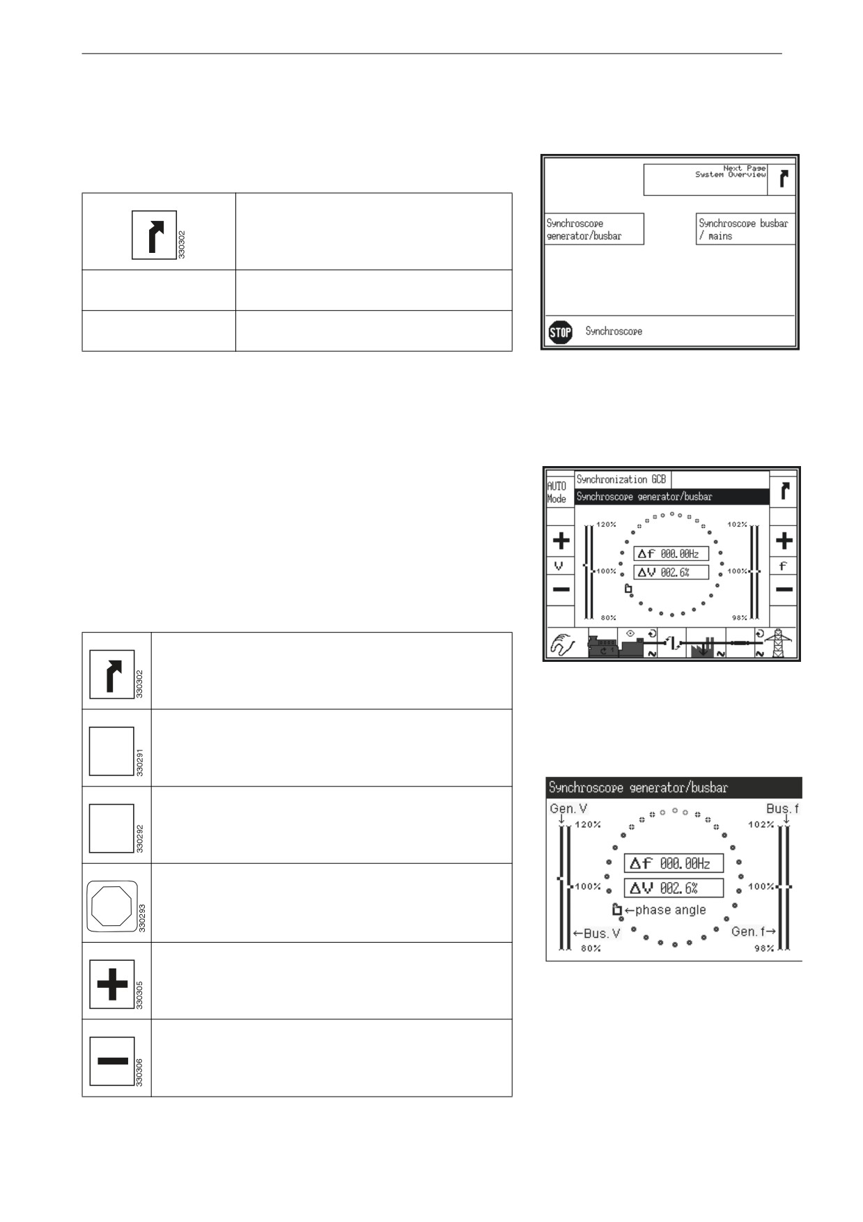
Synchroscope
This view is displayed when the display button Synchroscope in
the Next page view is pressed.
Return to view Next page.
Synchroscope genera-
Display view for synchroscope generator/
tor/busbar
busbar.
Synchroscope busbar/
Display view for synchroscope busbar/
mains
normal electrical power network.
Synchroscope
Synchroscope generator/busbar
This view is displayed when the display button Synchroscope
generator/busbar in the Synchroscope view is pressed.
The square symbol indicates the actual phase angle between bus-
bar and generator. The 12 o'clock position means 0° and the 6
o'clock position means 180°.
The frequency and voltage differences are displayed in the centre
of the circle.
Return to view Synchroscope.
Synchroscope generator/busbar
Switch to automatic operating mode.
"650
.PEF
Switch to manual operating mode.
."/
.PEF
Switch to operating mode stop.
4501
Increase voltage or frequency. Only displayed in manu-
al operating mode.
Display magnification
Decrease voltage or frequency. Only displayed in man-
ual operating mode.
10
Display navigation
Start or switch off the engine. Only displayed in manual
operating mode.
Open circuit breaker in the generator set or in the auto-
matic transfer switch. Only displayed in manual operat-
ing mode.
Close circuit breaker in the generator set or in the auto-
matic transfer switch. Only displayed in manual operat-
ing mode.
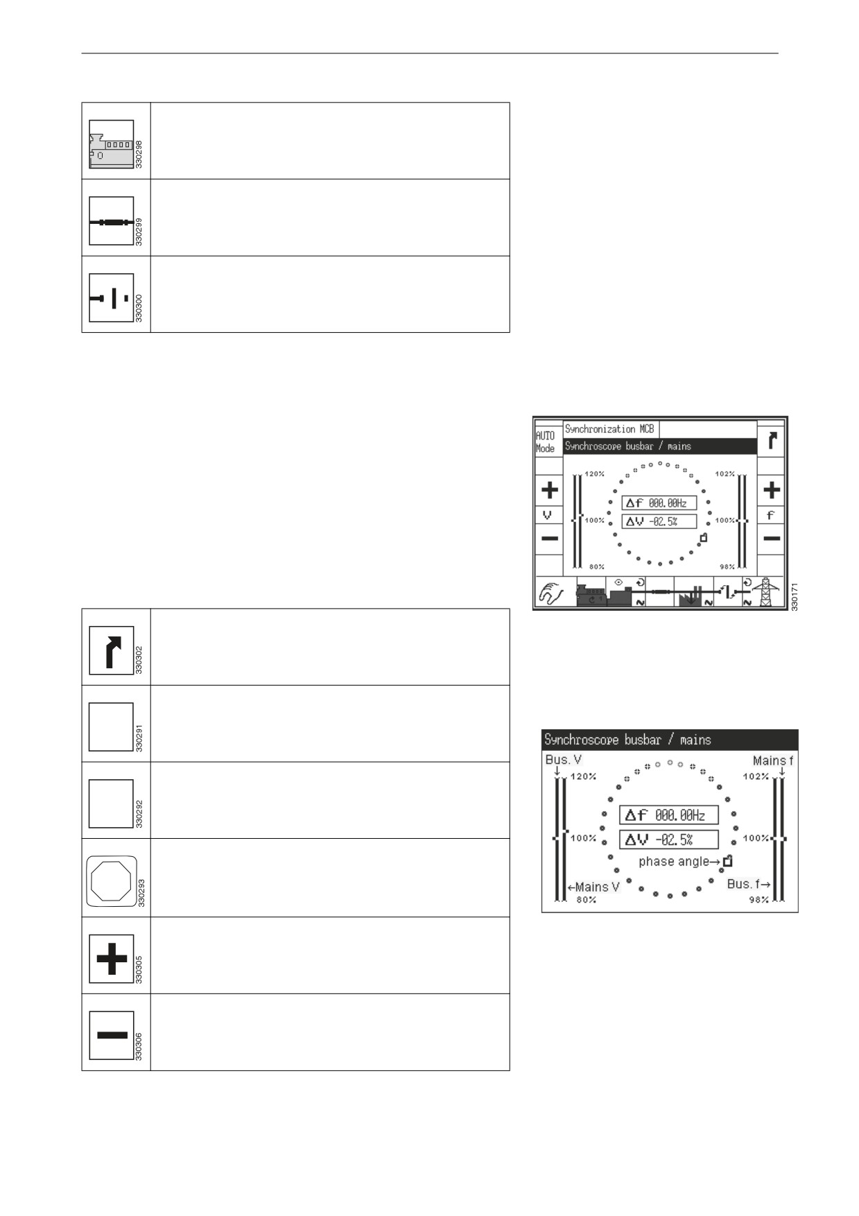
Synchroscope busbar/electrical power network.
This view is displayed when the display button Synchroscope
busbar/mains in the Synchroscope view is pressed.
The square symbol indicates the actual phase angle between the
busbar and the generator. The 12 o'clock position means 0° and
the 6 o'clock position means 180°.
The frequency and voltage differences are displayed in the centre
of the circle.
Return to view Synchroscope.
Synchroscope busbar/electrical power
network.
Switch to automatic operating mode.
"650
.PEF
Switch to manual operating mode.
."/
.PEF
Switch to operating mode stop.
4501
Increase voltage or frequency. Only displayed in manu-
Display magnification
al operating mode.
Decrease voltage or frequency. Only displayed in man-
ual operating mode.
11

Display navigation
Start or switch off the engine. Only displayed in manual
operating mode.
Open circuit breaker in the generator set or in the auto-
matic transfer switch. Only displayed in manual operat-
ing mode.
Close circuit breaker in the generator set or in the auto-
matic transfer switch. Only displayed in manual operat-
ing mode.
12
Display navigation
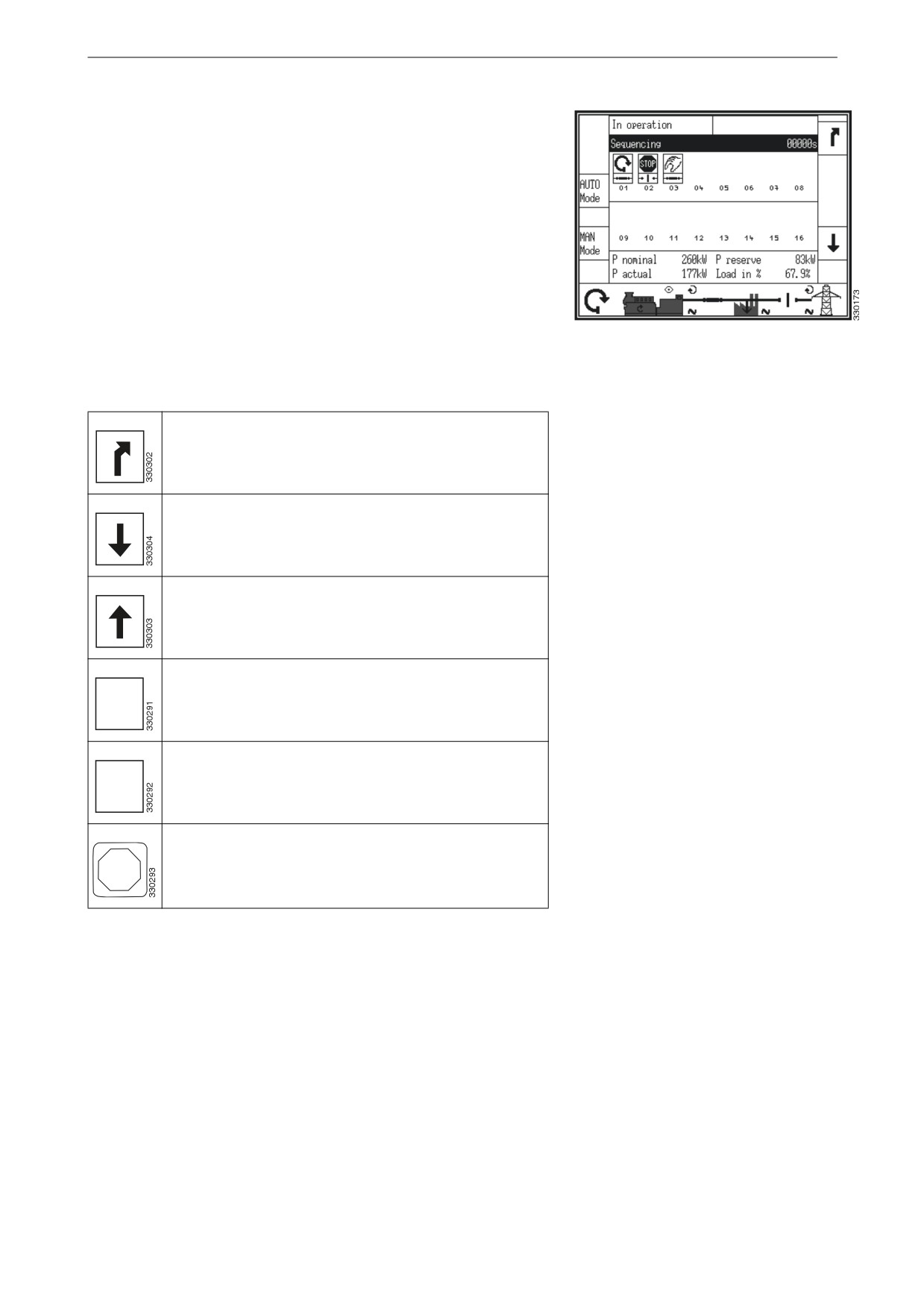
Load sharing
This view is displayed when the display button Sequencing in the
Next page view is pressed.
The load sharing view displays all generator sets participating in
load distribution. Operating state for each generator set as well as
the status of its circuit breaker are displayed.
The symbol above the generator number indicates the automatic,
stop or manual operating mode. The small bar indicates whether
the circuit breaker is closed or open.
The actual value of the load distribution is displayed below the
Load sharing
generator number. If this generator set is not participating in load
distribution, LD start stop OFF is displayed here.
Return to view Next page.
Scroll down to the display of the generator set 17 to 32.
Scroll up to the display of the generator set 1 to 16.
Switch to automatic operating mode.
"650
.PEF
Switch to manual operating mode.
."/
.PEF
Switch to operating mode stop.
4501
13
Display navigation
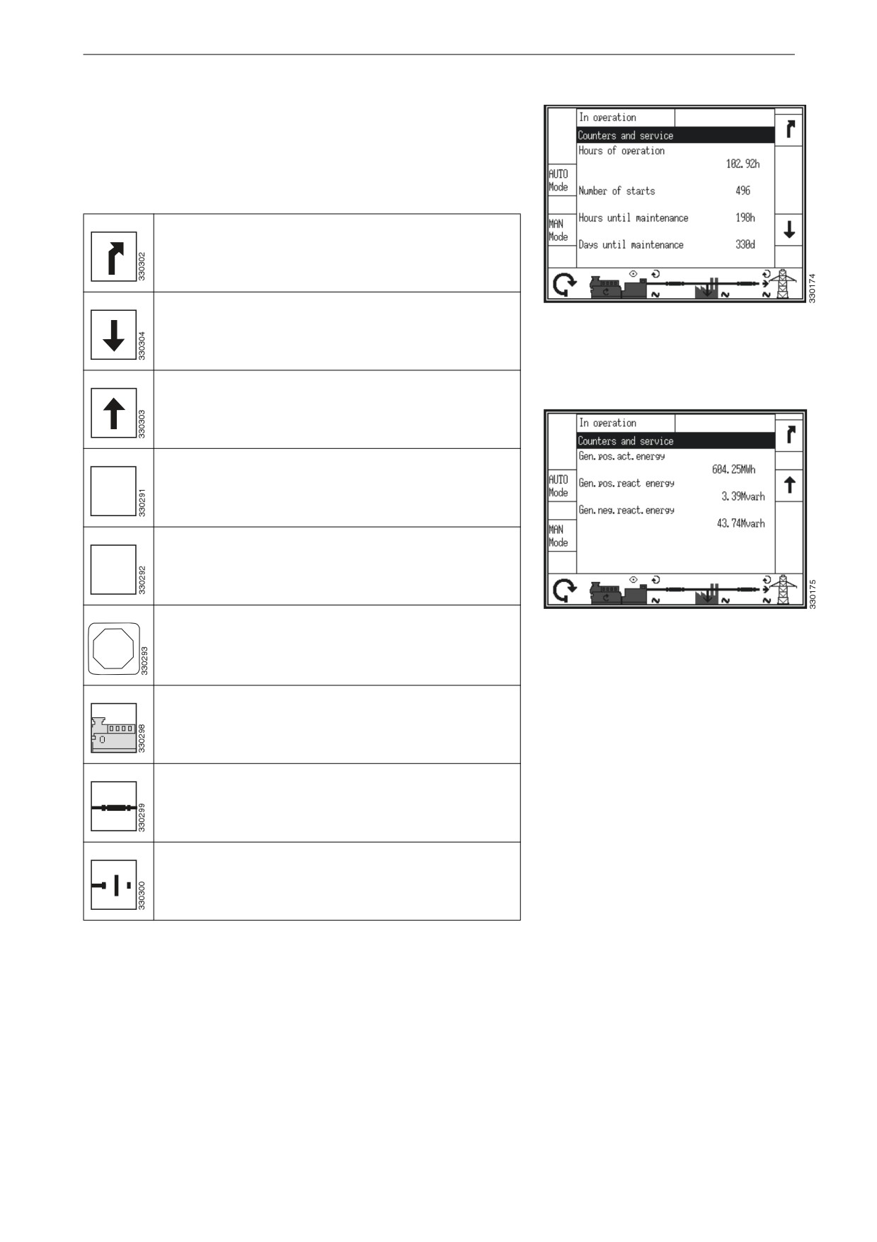
Counter and inspection
This view is displayed when the display button Counters and ser-
vice in the Next page view is pressed.
Return to view Next page.
Scroll down to the view for energy calculator.
Counter and inspection, timer
Scroll up to the view for timer.
Switch to automatic operating mode.
"650
.PEF
Switch to manual operating mode.
."/
.PEF
Switch to operating mode stop.
Counter and inspection, energy calculator
4501
Start or switch off the engine. Only displayed in manual
operating mode.
Open circuit breaker in the generator set or in the auto-
matic transfer switch. Only displayed in manual operat-
ing mode.
Close circuit breaker in the generator set or in the auto-
matic transfer switch. Only displayed in manual operat-
ing mode.
14

Display navigation
Displayed counters
Hours of operation
Indicates the total operating hours, the deci-
mals are hundredths of an hour.
Number of starts
Indicates the total number of starts.
Hours until main-
Indicates the number of hours to the next in-
tenance
spection.
Days until mainte-
Indicates the number of days to the next in-
nance
spection.
Gen. pos. act. en-
Generator positive active energy, total.
ergy
Gen. pos. react.
Generator positive reactive energy, total.
energy
Gen. neg. react.
Generator negative reactive energy, total.
energy
15