Scania EMS Instrumentation 1 920 778 - part 3

Example
Setting the LOW TEMP LIMIT (6.5.2)
- Press button 4 to continue.
- Enter the password and press button 3.
A warning screen is displayed.
- Press button 3, OK, to acknowledge the warning and proceed to the
parameters that can be set.
- Press button 2 or 3 to move up or down in the selection screen
- Press button 4 when for example LOW TEMP LIMIT has been
selected.
- Press button 4 again to display the setting screen.
- Press button 2 or 4 to increase or decrease the setting value.
- Press + or - to automatically delete the old value and enter the new
one.
- Press button 5 to return.
The same settings can be adjusted for the other parameters.
1920778
33
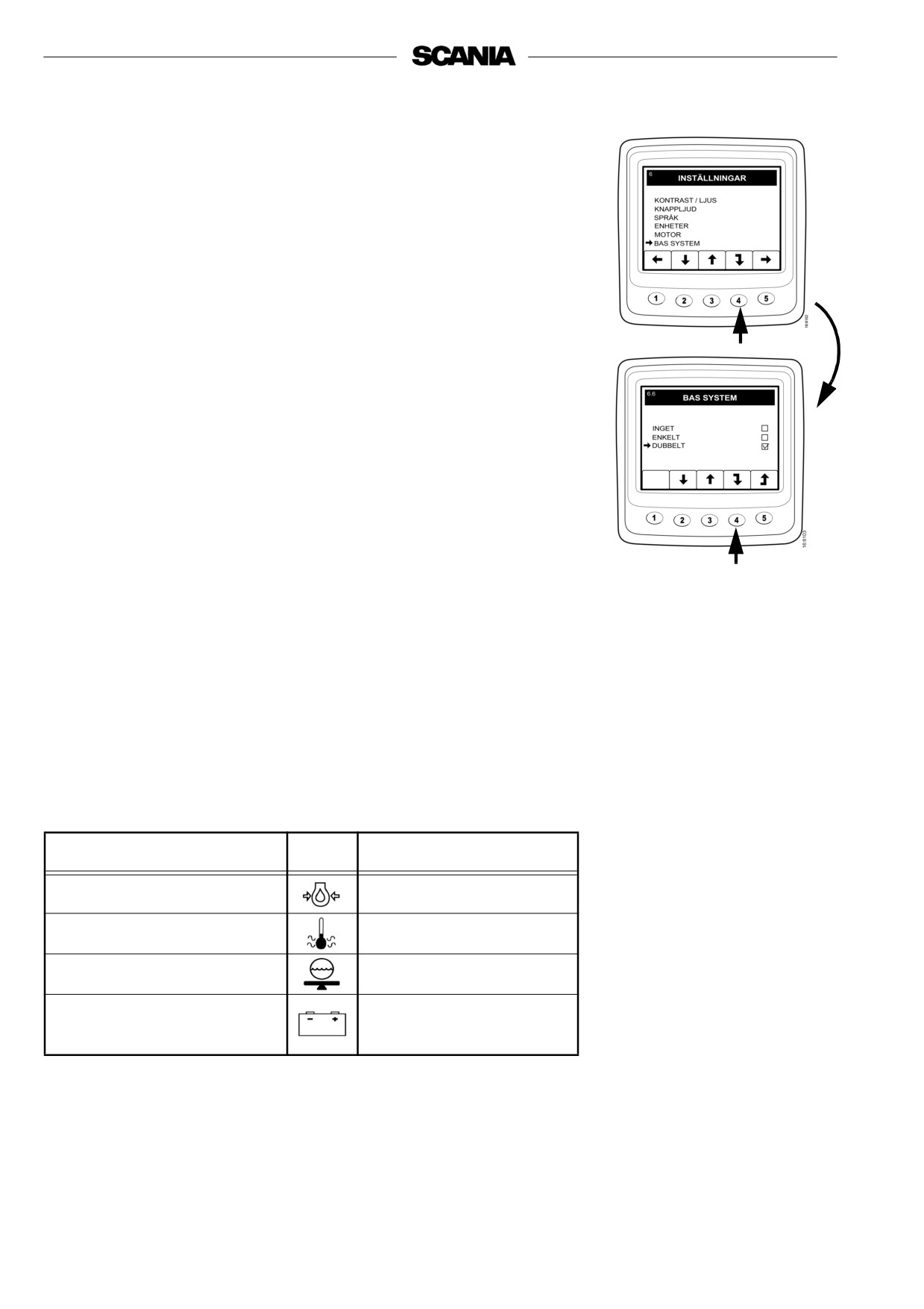
BASE SYSTEM (6.6)
Here it is possible to configure Scania EMS Display for the electrical
system to be used. The alternatives are NONE, SINGLE or DOUBLE.
- Press button 2 or 3 to go to BASE SYSTEM.
- Press button 4 to go to the selection screen.
- Press button 2 or 3 to select base system.
- Press button 4 to confirm the change. The box to the right will then
be marked, which means that the change has taken place.
- Press button 5 to return.
Alarm and fault code generation
Both new alarm and fault codes create dialogue boxes (pop-up boxes).
The alarm dialogue box has the highest priority for all functions in
Scania EMS Display.
Alarm
There are four different alarms available in the system:
Alarm
Icon
Remarks
Low oil pressure
High coolant temperature
Low coolant level
Alternator not charging
System voltage
displayed
34
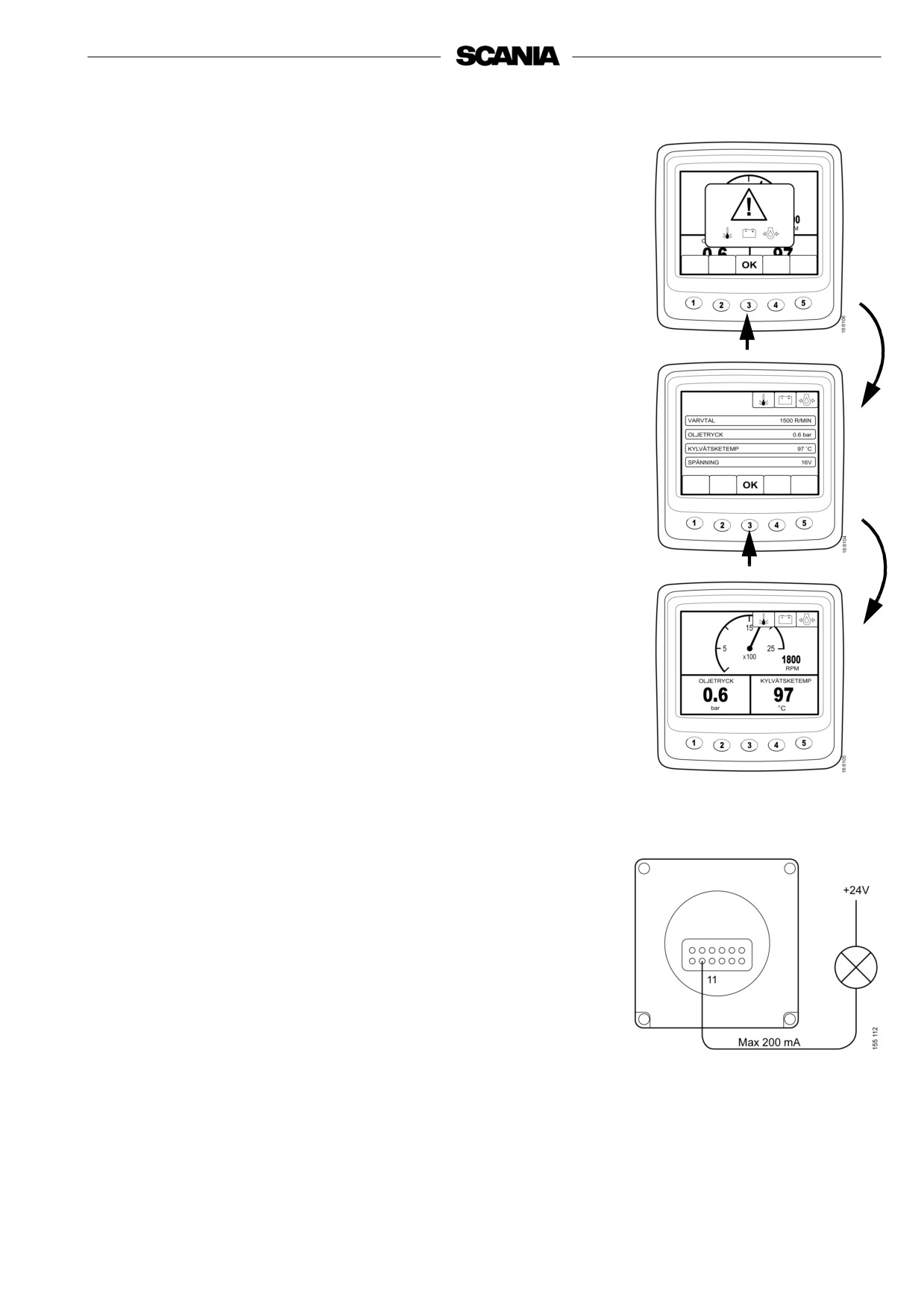
Function
When an alarm is created it is displayed as a warning on the basic
screen together with the alarm icon. The alarm signal sounds at the
same time both on the instrument panel and on Scania EMS Display.
The alarm signal on Scania EMS Display is confirmed by pressing
button 3, OK. If there are more alarms (icons), one alarm has to be
1.
confirmed at a time. Screen 1.
Each confirmed alarm is then displayed as an icon in the upper right
corner of the screen as long as a fault is active, regardless of which
screen is active.
Note: All alarms must be confirmed before the next screen will be
displayed.
The screen in illustration 2 always has the same content.
If you press button 3, OK, when in screen 2, you will return to the
screen displayed before the first alarm was generated, Screen 3.
2.
3.
External alarm signal
External alarm output
As soon as an alarm is present, pin 11 on the 12-pin display connector
is activated. The output can be used to activate a warning lamp or
similar. Pin 11 must be connected in order to earth a lamp or a relay
connected to +24V.
Maximum current 200 mA.
1920778
35
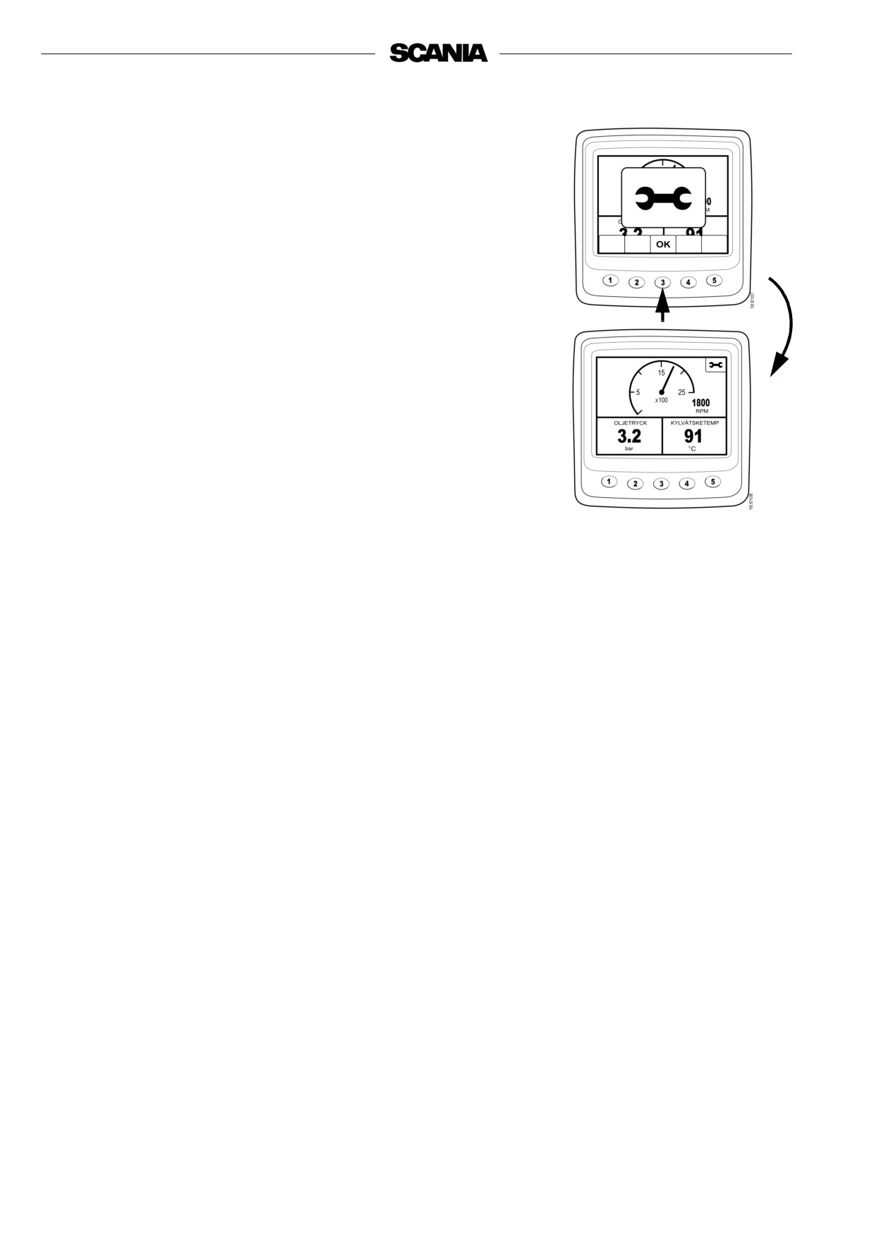
Fault code generation
There are several fault codes in the electrical system to help when a
system fault or engine fault occurs.
When a new active fault code is registered in the system, it will be
displayed on the screen as in illustration 1.
1.
Acknowledge all active fault codes by pressing button 3, OK. In the
next screen, a spanner icon is displayed in the upper right corner.
Screen 2.
This is displayed when at least one fault code is active.
It is not possible to see how many fault codes are active from these
screens. To see the fault codes that are present, go to the description of
Fault codes on page 20.
When starting the system a dialogue box as in illustration 1 is
displayed if there is at least one active fault code.
2.
36