Scania EMS Instrumentation 1 920 778 - part 1

Scania EMS
Instrumentation
1 920 778
1920778
1
Contents
Scania EMS Instrumentation
4
General
4
Instrument Panel (analogue)
6
General
6
Troubleshooting using flash codes for the EMS control unit
8
Overview of flash codes for EMS control unit
9
Troubleshooting using flash codes for the EMS coordinator
10
Overview of flash codes for EMS coordinator
11
Scania Control Panel (SCP)
12
Remote Control Box (RCB)
17
Scania EMS Display (SED)
19
General
19
Function
19
Favourites screen
19
Information (4)
22
Fault codes (5)
24
Settings (6)
26
Alarm and fault code generation
34
1920778
3
Scania EMS Instrumentation
General
The base system consists of the main supply box (MSB), the junction
box for the coordinator (CBC) and the coordinator (COO). The main
supply box is connected directly to the S6 control unit.
This base system has several different options for connection to the
system:
- Scania EMS digital display combined with a control panel with a
starter key.
- A remote control box which allows the engine to be controlled from
the engine room.
- An analogue instrument panel instead of the digital display or
combined with it.
- A Scania APS sensor (accelerator pedal sensor).
- In addition, the system can be doubled if there are two control
desks.
The whole instrumentation system is Plug and Play which makes it
very simple to install.
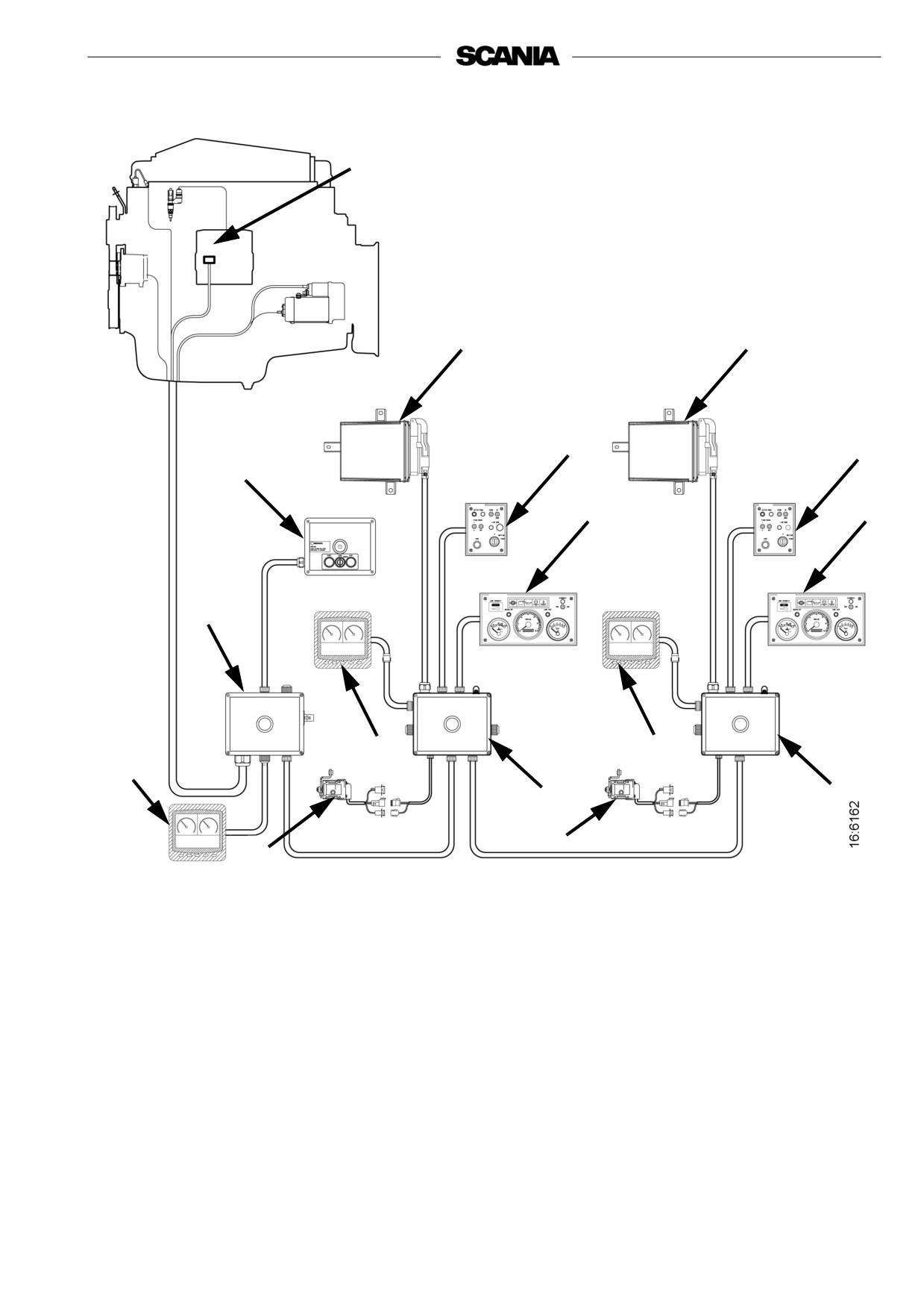
See illustration of dual system on the next page.
In this Operator’s Manual, only the analogue instrument panel 9,
Scania EMS display 10 and Control Panel 8 and 9, are described.
4
1
3
4
7
8
12
9
9
2
10
10
10
5
6
11
11
1. Control Unit S6
2. Main Supply Box
3. Coordinator
4. Coordinator
5. Connection Box Coordinator (master)
6. Connection Box Coordinator (slave)
7. Control Panel (master)
8. Control Panel (slave)
9. Instrument Panel
10. Scania EMS Display
11. Accelerator Position Sensor
12. Remote Control Box
Scania instrumentation, dual system
1920778
5
Instrument Panel (analogue)
General
The analogue instrument panel has instruments for reading the rotation
speed with hour counter, coolant temperature and oil pressure, as well
as switches and lamps for diagnosis and alarms.
The analogue instrument panel incorporates the following functions:
Also see illustration on next page.
Lamp intensity (S54)
The intensity of the gauges can be regulated with this roller control.
Buzzer off (S51)
This button deactivates the buzzer sound on any existing alarm. The
warning lamp for the current alarm trigger will remain illuminated
until the fault is rectified.
Lamp test (S52)
This button is used to check that the system lamps are intact and
functioning. When the button is activated, the coordinator will activate
all lamps on the panel and the buzzer will sound. The lamps illuminate
and the buzzer sounds as long as the button is depressed.
When the key in the control panel (Control Panel) is turned to the
Ignition position, an automatic lamp test takes place for 2 seconds and
the buzzer sounds for 1 second.
Diagnosis EMS/COO (W21 and S53)
This is a 3 position switch which is linked to diagnostics lamp W21.
The diagnostic lamp remains lit for as long as the system has an active
fault code.
When the switch is activated in the COO direction for at least 1 second,
the coordinator will transmit any fault codes as flash codes on the
diagnostic lamp (W21).
When the switch is activated in the EMS direction for at least 1 second,
the coordinator will transmit any fault codes for the EMS the control
unit as flash codes on the diagnostic lamp (W21).
6
In order to read flash codes with dual instrumentation it is necessary to
request diagnosis from the instrument panel to which the coordinator
concerned is connected.
For further information on reading and deleting flash codes, see
Troubleshooting using flash codes.
Warning lamps (W1, W4, W5, W6, W7)
On the warning lamp panel there are warning lamps for alternator
charging, oil pressure, coolant temperature and coolant level. The
warning lamp for hydraulic pressure is not used.
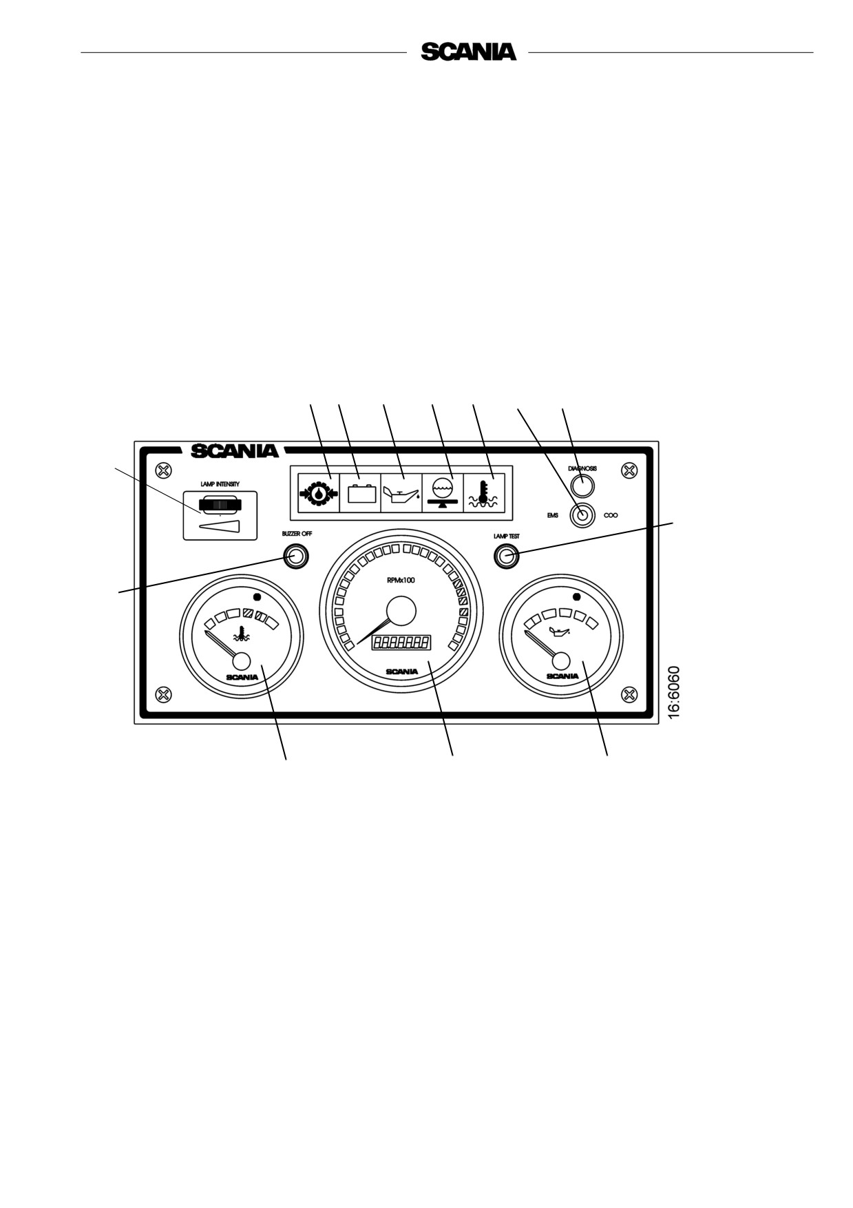
W6 W1 W5 W7 W4 S53 W21
S54
S52
S51
O1
O3
O2
O1
Tachometer with hour counter
O2
Coolant temperature gauge
O3
Oil pressure gauge
S51 Buzzer deactivation
S52 Lamp test switch
S53 Diagnostic switch
S54 Instrument lighting rheostat
W1 Charge indicator lamp
W4 Warning lamp, coolant temperature
W5 Warning lamp, oil pressure
W6 Warning lamp, hydraulic pressure
W7 Warning lamp, coolant level
W21 Diagnostic lamp
Scania analogue instrument panel
1920778
7
Troubleshooting using flash codes for the EMS
control unit
1.
Switch on the ignition. If the diagnostics lamp remains on after
2 seconds there is an active fault.
2.
Activate the diagnostic switch (S53) to the left to see the flash
codes for the control unit (EMS).
3.
A fault code will then flash on the diagnostics lamp (W21). This
flash code consists of long flashes (approximately 1 second long)
and short flashes (0.3 seconds long). Long flashes are equivalent
to tens and short flashes to ones.
Example: long - short - short = fault code 12.
4.
Repeat this procedure until the first flash code is repeated. This
means that the entire fault code memory has been flashed out. If
the fault code memory is empty, only one long flash
approximately 4 seconds long will be given.
5.
See the flash code table on the next page for a description and to
locate the fault.
6.
For further information about the fault code the PC based
diagnostic tool or Scania EMS Display must be used. Contact an
authorised Scania workshop.
7.
The diagnostics lamp will stay on for as long as a fault is active.
Even if the lamp has gone off and the fault is no longer active, the
code can generally be read off in accordance with the instructions
above.
8.
When a fault has been rectified the fault code can be erased as
described below.
Deleting fault codes (flash codes)
1. Turn the ignition off. If the vessel has dual instrumentation, the
ignition must be switched off on both panels.
2. Activate the diagnostics switch in the direction of the flash codes,
i.e. to the left for EMS.
3. Turn the ignition on at the same time as holding the diagnostics
switch activated to the left (EMS) for 3 seconds.
4. This will erase passive fault codes which can be read off via flash
codes for the relevant system. The rest of the fault codes will
remain in the EEPROM and can only be deleted using the PC tool.
8

Overview of flash codes for EMS control unit
Code
Description
Code
Description
No fault detected.
PDE in cylinder 3: The solenoid valve does not
0
53
work correctly.
Over-revving. One or both engine speed
PDE in cylinder 4: The solenoid valve does not
11
54
sensors shows a speed in excess of 3,000 rpm.
work correctly.
Engine speed sensor 1 faulty, or incorrect
PDE in cylinder 5: The solenoid valve does not
12
55
signal.
work correctly.
Engine speed sensor 2 faulty, or incorrect
PDE in cylinder 6: The solenoid valve does not
13
56
signal.
work correctly.
Coolant temperature sensor faulty, or incorrect
PDE in cylinder 7: The solenoid valve does not
14
57
signal.
work correctly.
Charge air temperature sensor faulty, or
PDE in cylinder 8: The solenoid valve does not
15
58
incorrect signal.
work correctly.
Charge air pressure sensor faulty, or incorrect
Incorrect signal in extra analogue input.
16
59
signal.
Oil temperature sensor faulty, or incorrect
Incorrect control unit shutdown.
17
61
signal.
18
Oil pressure sensor faulty, or incorrect signal.
66
Shutdown due to coolant level.
21
Coolant level sensor faulty.
68
Alternator charging incorrectly.
Internal fault code in the coordinator.
Starter motor function interrupted or not
23
69
activated.
Accelerator/brake. If the accelerator and brake
Engine speed above ref. engine speed at start.
24
82
pedals have been operated simultaneously.
Accelerator sensor/idle switch.
Fault in memory circuit (EEPROM) in control
25
83
unit.
Accelerator sensor/kickdown switch.
Engine shutdown bypassed.
Data transfer to the control unit memory
27
84
(EEPROM) has been interrupted.
Shutdown due to oil pressure.
Incorrect internal temperature in the control
28
85
unit.
Torque limitation due to oil pressure.
Internal fault in the control unit: Fault in
31
86
hardware control.
32
Incorrect parameters for limp home function.
87
Fault in control unit RAM.
33
Battery voltage incorrect or no signal.
88
Internal control unit fault: Memory fault.
Emergency shutdown switch activated in
Incorrect seal: Prohibited changes in software.
37
accordance with CAN message from
89
coordinator.
43
CAN circuit faulty in the control unit.
93
Engine speed sensors faulty or not connected.
Immobiliser function. Starter key code
Shutdown due to high coolant temperature.
47
94
incorrect.
CAN message from the coordinator incorrect
Torque limitation due to high coolant
48
96
or missing.
temperature.
Incorrect CAN version in control unit or
Incorrect voltage supply to one of the sensors.
49
98
coordinator.
PDE in cylinder 1: The solenoid valve does not
Internal hardware fault in the processor (TPU).
51
99
work correctly.
PDE in cylinder 2: The solenoid valve does not
52
work correctly.
1920778
9
Troubleshooting using flash codes for the EMS
coordinator
1. Switch on the ignition. If the diagnostics lamp remains on after
2 seconds there is an active fault.
Important! The diagnostics lamp only indicates faults for the
coordinator connected to the instrument panel from which the
flash codes are read.
2.
Activate the diagnostics switch (S53) to the right to see the flash
codes for the coordinator (COO).
3.
A fault code will then flash on the diagnostics lamp (W21). This
flash code consists of long flashes (approximately 1 second long)
and short flashes (0.3 seconds long). Long flashes are equivalent
to tens and short flashes to ones.
Example: long - short - short = fault code 12.
4.
Repeat this procedure until the first flash code is repeated. This
means that the entire fault code memory has been flashed out. If
the fault code memory is empty, only one long flash
approximately 4 seconds long will be given.
5.
See the flash code table on the next page for a description and to
locate the fault.
6.
For further information about the fault code the PC based
diagnostic tool or Scania EMS Display must be used. Contact an
authorised Scania workshop.
7.
The diagnostics lamp will stay on for as long as a fault is active.
Even if the lamp has gone off and the fault is no longer active, the
code can generally be read off in accordance with the instructions
above.
Deleting fault codes (flash codes)
1. Turn the ignition off. If the vessel has dual instrumentation, the
ignition must be switched off on both panels.
2. Activate the diagnostic switch in the direction of the flash codes,
i.e. to the right for the coordinator (COO).
3. Turn the ignition on at the same time as holding the diagnostic
switch activated to the right (COO), for 3 seconds.
4. Any fault code that can be read by a flash code for the system in
question will be deleted. The rest of the fault codes will remain in
the EEPROM and can only be deleted using the PC tool.
Important! It is only possible to delete fault codes for the
coordinator that is connected to the instrument panel from
which deletion is carried out.
10

Overview of flash codes for EMS coordinator
Flash
Fault description
code
111)
Incorrect signal from the fine adjustment for the nominal engine speed signal.
112)
Incorrect analogue signals from the accelerator pedal sensor.
121)
Incorrect analogue signal from the resistor module for governor setting.
122)
Incorrect analogue signal from the resistor module for idling and fixed speed
setting.
13
No communication (EMS) with the engine.
14
Short-circuit in the tachometer signal circuit.
15
Faulty atmospheric pressure sensor.
17
Short-circuit in the coolant temperature gauge signal cable.
18
Short-circuit in the oil pressure gauge signal circuit.
19
Short-circuit in the oil pressure lamp signal circuit.
21
Different versions of the communications protocol between the coordinator and
EMS.
22
Faulty start switch or short circuit.
23
Supply voltage too high.
24
Supply voltage too low.
25
Check value from end of line (EOL) is incorrect.
26
Speed sensor signal missing or incorrect.
27
The signals from the RCB (Remote Control Box) switches are implausible.
28
Incorrect signals from the droop setting switches.
29
Faulty remote start switch or short circuit.
31
No communication from the slave coordinator or the master coordinator.
32
Short circuit in the signal cable to the coolant temperature warning lamp.
33
Short circuit in the signal cable to the charge warning lamp.
34
Incorrect signal from the Fixed speed switches.
35
Fault in CAN communication.
1) Single speed engine
2) All-speed engine
1920778
11

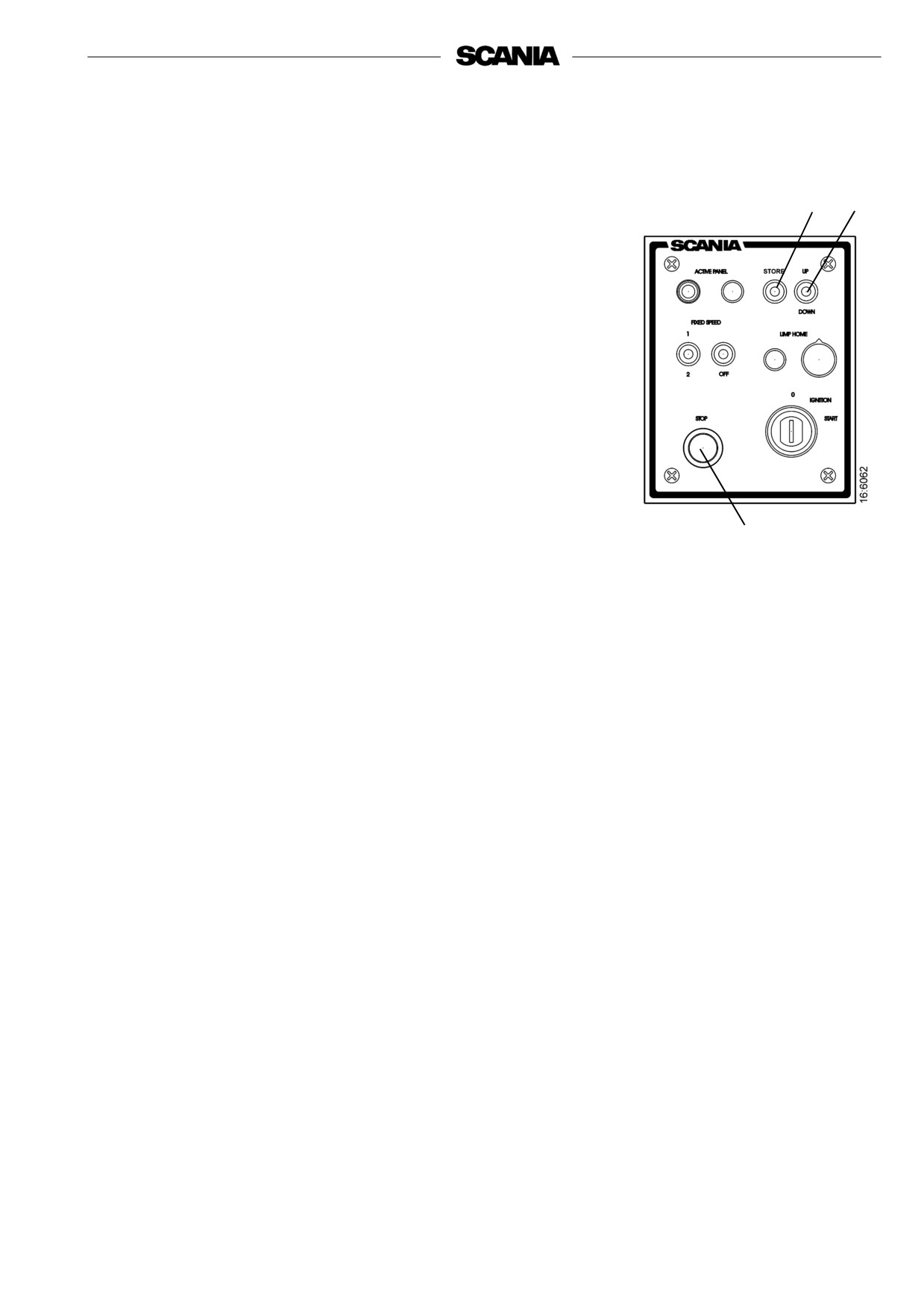
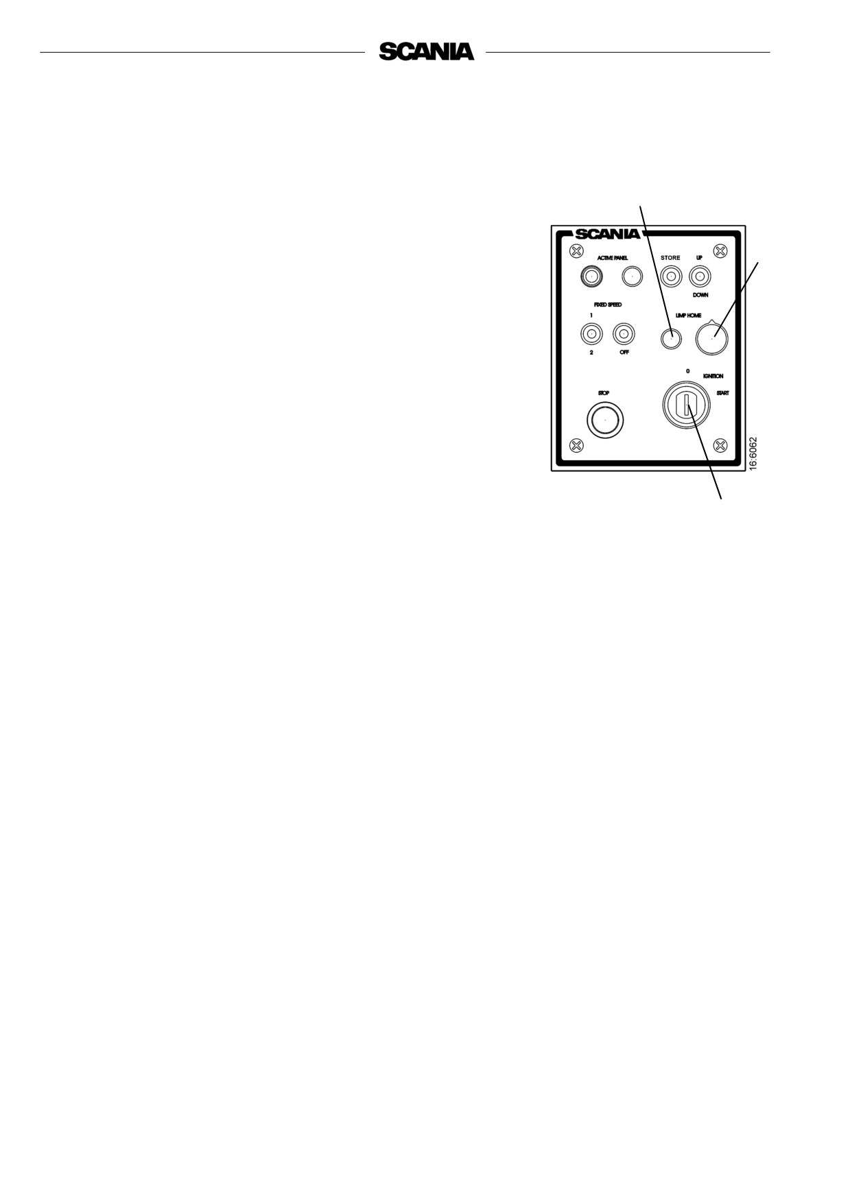
Scania Control Panel (SCP)
Start and stop the engine from the Scania Control Panel which has a
starter key and a stop button together with functions for Fixed Speed
and Limp Home.
S42
W19S45 S47
S49
S43
W20
S46
S1
S50
W20
2
1
1
Master panel
2
Slave panel
W19 Lamp for Active Panel
W20 Lamp for Limp Home Throttle
S1
Starter key
S42 Switch to activate Active Panel function
S43 Switch for activating and switching between Fixed Speed 1 and 2
S45 Switch for storage
S46 Stop button
S47 Switch for adjusting Fixed Speed/Idle Speed up or down
S49 Switch for deactivating Fixed Speed function
S50 Potentiometer for Limp Home Throttle
Scania Control Panel with starter key
12
The following functions are available in Scania Control Panel:
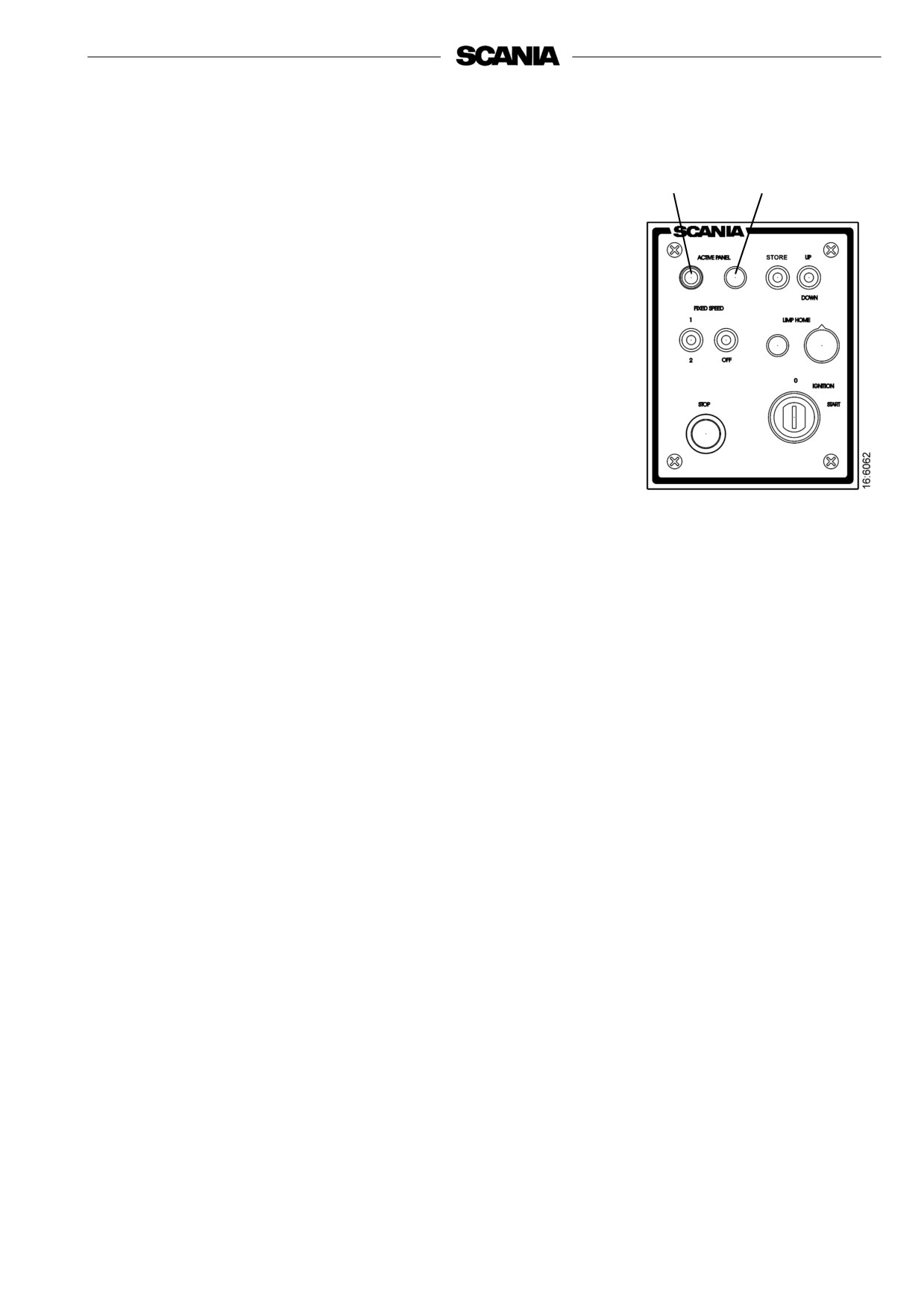
Active Panel
Activate the panel by depressing pushbutton S42. The coordinator
S42
W19
registers that this control position is active and switches on lamp W19.
The panel from which the engine is started is automatically active and
it is then possible to make adjustments and request throttle actuation.
In order to change active panel (changing throttle position), both
throttle controls must be at 0% throttle. Switch off the active panel so
that neither panel is active. Then it is possible to change control
position.
With single instrumentation, the panel is activated when the key is
turned to the ignition position.
If the throttle control fails, the Active Panel lamp is still illuminated
and the Limp Home lamp comes on which means that the limp home
throttle (emergency throttle) is engaged.
If CAN communication fails, the Limp Home lamp comes on and the
Limp Home throttle is engaged.
See also under Limp Home Throttle.
1920778
13
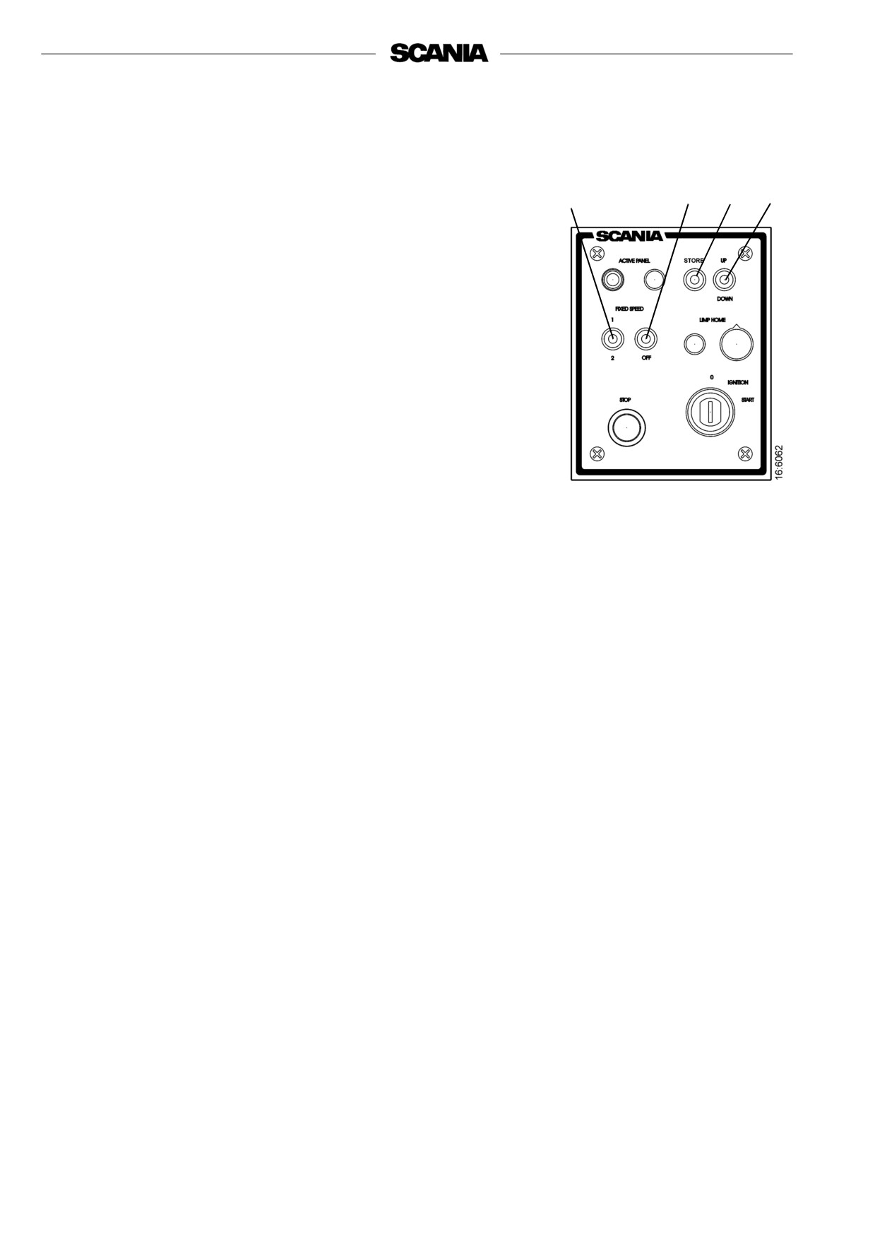
Fixed Speed 1 and 2
These two functions are activated via a 3-position switch, S43. With
Fixed Speed 1, it is possible to set an isochronous speed between high
and low idle speed. With Fixed Speed 2 it is possible to set an
isochronous speed between 450 and 2,000 rpm. In both modes, it is
S49
S45
S47
S43
possible to set torque limitation via the diagnostic tool or the digital
display.
During activation, the engine goes up or down to the last saved value
for the mode.
The conditions for activating these modes are that the engine is
running, the panel is active and the throttle is at 0%.
Change the speed for either modes in the following way:
- Activate the mode to be changed by moving switch S43 to 1 or 2.
- Adjust the speed up or down using switch S47.
- Press Store switch S45 for 3 seconds to save the new values. If you
exit the mode without saving, the engine will resume the last speed
value that was stored for that mode.
- When using dual instrumentation it is only possible to make
adjustments from the panel that is active.
- In order to deactivate the function, press switch S49 to Off, touch
the accelerator pedal, change the panel when using dual
instrumentation, or switch off the engine.
14
Idling speed adjustment
Reset the engine idle speed as follows:
1. Activate Store switch S45 for 3 seconds in order to go to
adjustment mode.
S45
S47
2. Adjust the idle speed up or down (+ or -) using switch S47.
3. Save the set value by activating the Store switch for
3 seconds.
- It is also possible to set the engine idle speed using the diagnostic
tool or Scania digital display.
- In order to reset the idle speed the coolant temperature must not be
higher than 50°C with the engine running at idle.
- The idle speed can be set to between 500 and 1,050 rpm.
Stop
The engine stop function is available in several places in the system.
With single instrumentation the stop button is in 2 places:
- In the Remote Control Box (RCB).
S46
- In the Control Panel (S46).
With dual instrumentation, the stop button can be located in 3 places:
- In the Remote Control Box (RCB).
- In both Control Panels (S46).
When one of these buttons is activated COO sends a message to S6 to
stop the engine.
It is also possible to stop the engine by turning the key to O. With dual
instrumentation it is possible that both Control Panels are in ignition
position and both keys must then be turned to O.
We therefore recommend that the engine is stopped with a stop
button.
1920778
15
Limp Home Throttle
Limp Home Throttle is an emergency throttle function which is
activated if the master coordinator fails or if the master throttle control
fails when the master control position is active, or if the slave throttle
control fails when the slave control position is active or if CAN traffic
W20
fails.
If any of the above should occur, the Limp Home lamp W20 will come
on and the Limp Home Throttle will be engaged.
S50
Limp Home Throttle, S50, consists of a potentiometer on the master
Control Panel which can be operated in limp home mode. The
potentiometer value goes directly to switch A2 on the S6 control unit.
In order to use Limp Home Throttle, the potentiometer must first be
turned to the 0 position before it is activated. The potentiometer is only
on the Master Control Panel. There is a Limp Home lamp on both
panels. If CAN fails, both the lamps will come on and the Limp Home
Throttle will become active.
The potentiometer is only on the master panel but Limp Home lamp
W20 is on both panels.
If the master control fails when the master panel is active, the lamps on
both panels will come on. If you then change to the slave panel, both
S1
lamps will go off and it is possible to control the engine throttle via the
slave panel.
The same will also apply the other way round.
Start Key
Start the engine by using key S1 on Scania Control Panel. The key
generates a U15 signal in the Ignition position and a U50 signal in the
Start position.
When the coordinator receives a signal from the key to start, the
coordinator sends a CAN message to the S6 control unit, which in turn
sends a signal to the starter relay that supplies the starter motor with
power and the engine starts.
- If a panel is active, it is only possible to start the engine from that
panel.
- If no panel is active, the panel that you use to start the engine will
automatically become active.
The engine stops when the key is turned to the 0 position. This only
applies if the other key in a dual system is not turned on.
16