Scania Marine engine. DI13 XPI. Operator’s manual - part 4
Cooling system
Checking coolant level
WARNING!
Do not open the coolant filler cap in the expan-
sion tank if the engine is hot. Hot coolant and
steam may spray out and cause burns. If the cap
has to be opened do it slowly to release the pres-
sure before removing the cap.
Use protective gloves as coolant can cause irrita-
tion if it comes in contact with the skin.
IMPORTANT!
It is not permissible to top up large amounts of
coolant via the expansion tank. Filling via the ex-
pansion tank leads to air locks in the cooling sys-
tem which can lead to e.g. cavitation damage to
the coolant pump shaft seal. If a large amount of
coolant needs to be added, follow the instruc-
tions in the section Filling coolant.
Only pour pre-mixed coolant into the cooling
system.
The following instructions apply to Scania ex-
pansion tanks. For other types of expansion
tanks, follow the manufacturer's instructions.
1. Check the coolant level through the sight
glass on the expansion tank.
2. Top up with coolant as necessary.
48

Cooling system
Checking coolant antifreeze
and corrosion protection
Tool
Designation
Illustration
Refractometer
WARNING!
Avoid skin contact with coolant as this may
cause irritation to the skin. Wear protective gog-
gles and gloves when handling coolant.
IMPORTANT!
Use only pure fresh water that is free from parti-
cles, sludge and other impurities.
1. Pour a small amount of coolant into a con-
tainer and check that the coolant is pure and
clear.
2. Change the coolant if it is contaminated or
cloudy.
3. Measure the antifreeze and corrosion inhibi-
tor content with the refractometer.
The following rules apply to ethylene glycol-
based coolant:
• The antifreeze and corrosion inhibitor content
must be minimum 35 percent by volume for
corrosion protection to be sufficient.
• An antifreeze and corrosion inhibitor content
greater than 55 percent by volume impairs the
ability to protect against frost.
• If ice forms in the coolant, there are disrup-
tions initially, but there is no immediate risk
of damage. The engine should not be subject-
ed to heavy loads when ice starts to form.
49
Cooling system
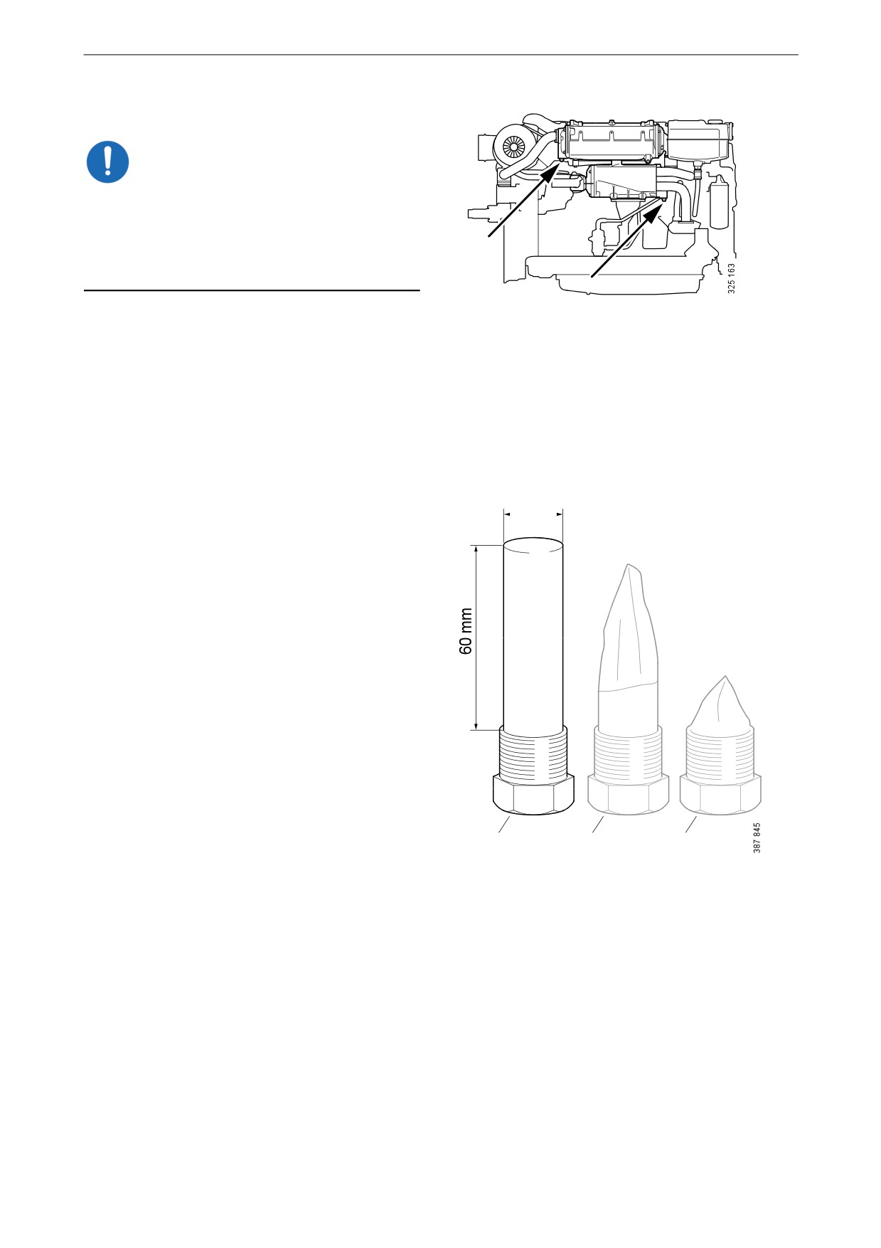
Checking sacrificial anodes
IMPORTANT!
Corrosion of sacrificial anodes depends on the
operating environment. Therefore, check the
sacrificial anodes every third month during the
first year of commissioning or when changing
the operating environment.
Position of sacrificial anodes.
1. Drain the sea water circuit as described in the
Draining the sea water circuit section.
2. Remove all sacrificial anodes.
3. Check all sacrificial anodes:
17 mm
- Scrape off all loose material and check the
corrosion.
- Renew all sacrificial anodes if there is less
than ¾ (2) remaining of any of the sacrifi-
cial anodes.
- If the sacrificial anodes are very corroded
(3), the length of the intervals for checking
the sacrificial anodes should be halved. If
the sacrificial anodes are very corroded,
they often come loose entirely.
4. Renew the gasket when fitting.
1
2
3
1. New sacrificial anode.
2. Approx. 3/4 remains.
3. Approx. 1/4 remains.
50

Cooling system
Checking the sea water pump
impeller
1. Drain the sea water circuit as described in the
Draining the sea water circuit section.
2. Remove the sea water pump cover. See illus-
tration.
3. Check that the vanes of the impeller are not
heavily splintered or damaged.
Renewing the sea water pump impel-
ler
Special tool
Number
Designation
Illustration
98 482
Puller
Note:
If the impeller must be renewed frequently, the
cleaning of the sea water needs to be improved.
There should be a spare impeller and puller on
board.
The impeller can be deformed during extended
periods of inactivity. Renew the impeller before
starting or remove the impeller before longer pe-
riods of stoppage.
1. Pull out the impeller using the puller. Note
the direction of rotation of the impeller
vanes.
2. Fit a new impeller and cap. Check that the
cap seal is not hard or damaged.
IMPORTANT!
When fitting the new impeller, bend the vanes in
the same direction as on the old one.
51
Cooling system
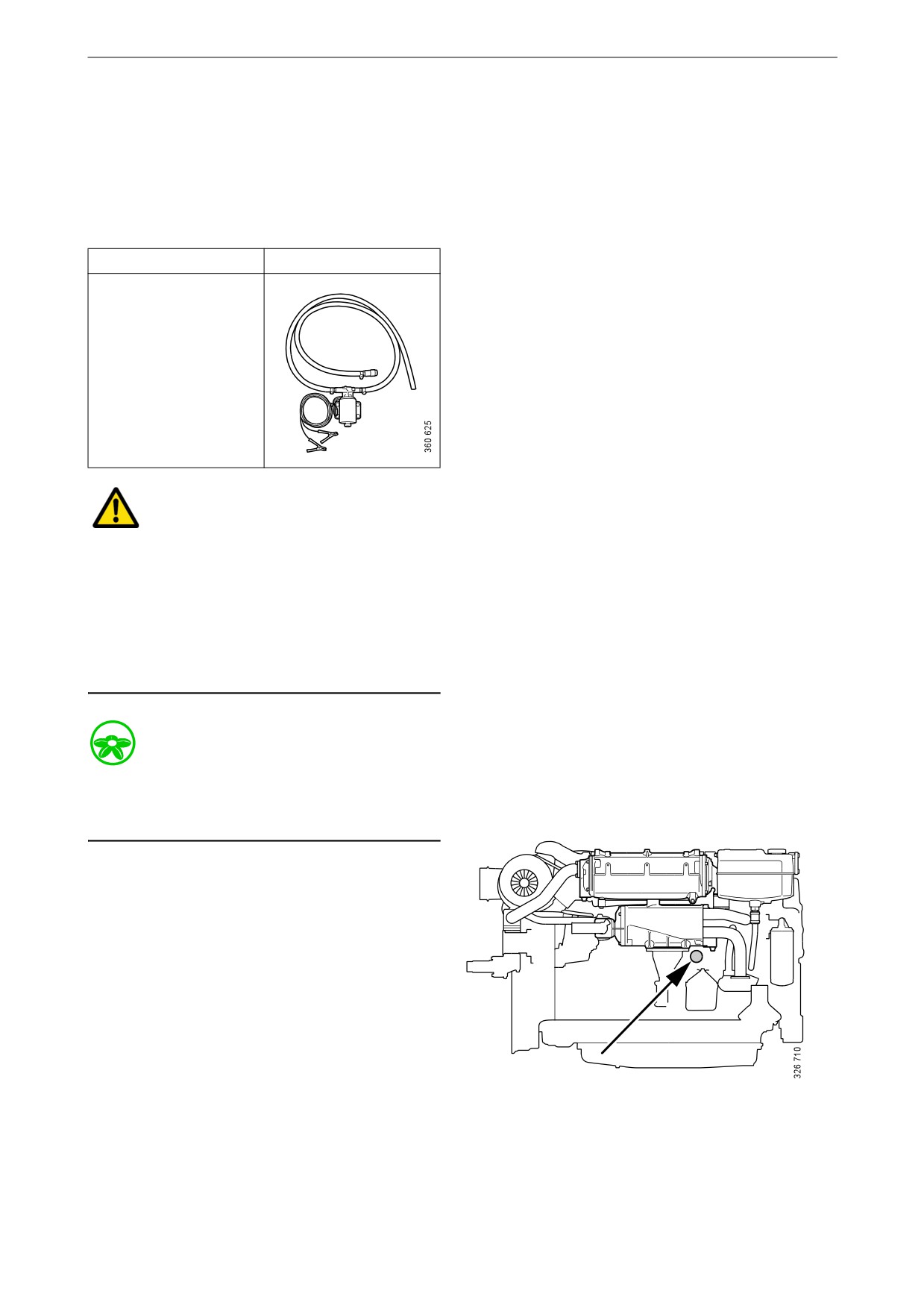
Changing the coolant and
cleaning the cooling system
Draining coolant
Special tool
Number, designation
Illustration
2 443 679, coolant
pump
WARNING!
Do not open the coolant filler cap in the expan-
sion tank if the engine is hot. Hot coolant and
steam may spray out and cause burns. If the cap
has to be opened do it slowly to release the pres-
sure before removing the cap.
Use protective gloves as coolant can cause irrita-
tion if it comes in contact with the skin.
Environment
Use a suitable container. Used coolant must be
disposed of as specified in national and interna-
tional laws and regulations.
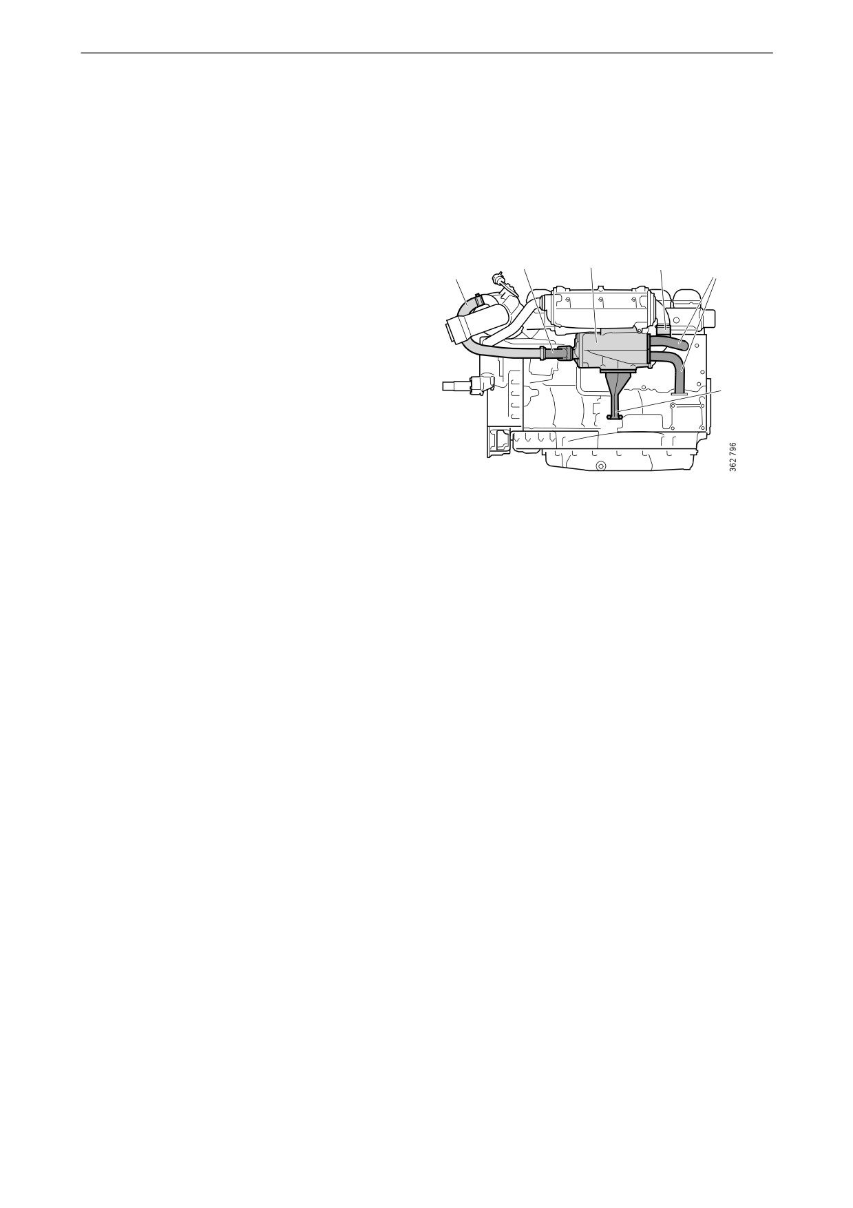
1. Open the expansion tank cap.
2. Position the hose from the coolant pump in
an empty container.
3. Connect the pump to the draining nipple in
the cylinder block. See illustration.
4. Connect the pump's 2 cable terminals to the
battery's negative and positive terminal.
Make sure that the drainage starts. If the
drainage does not start: Change the position
of the cable terminals.
5. Repeat the procedure at the cooling system's
Drain nipple in the cylinder block.
lowest drainage point. The location of the
lowest drainage point on the engine may dif-
fer depending on engine application.
52

Cooling system
Draining the sea water circuit
3
2
1
1. Close the bottom valve on the sea water inlet
and remove the connection pipe (1) on the
outlet from the heat exchanger.
2. Remove the cover (2) from the sea water
pump to empty the pump completely.
The lowest point in the sea water circuit may be
at different points, but it is usually in the sea wa-
ter pump intake (3).
IMPORTANT!
Plug the connections to prevent dirt ingress into
the engine.
53
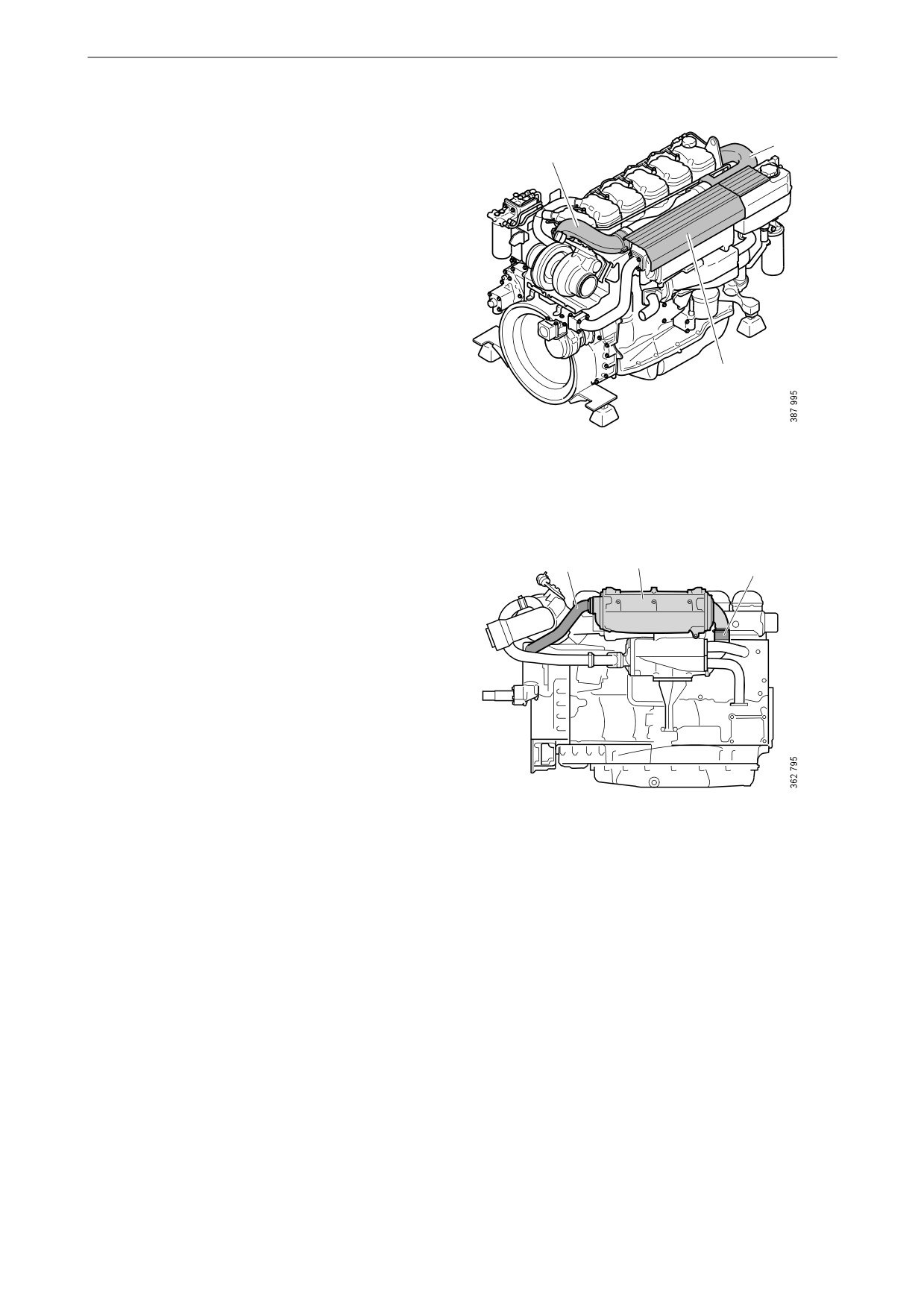
Cooling system
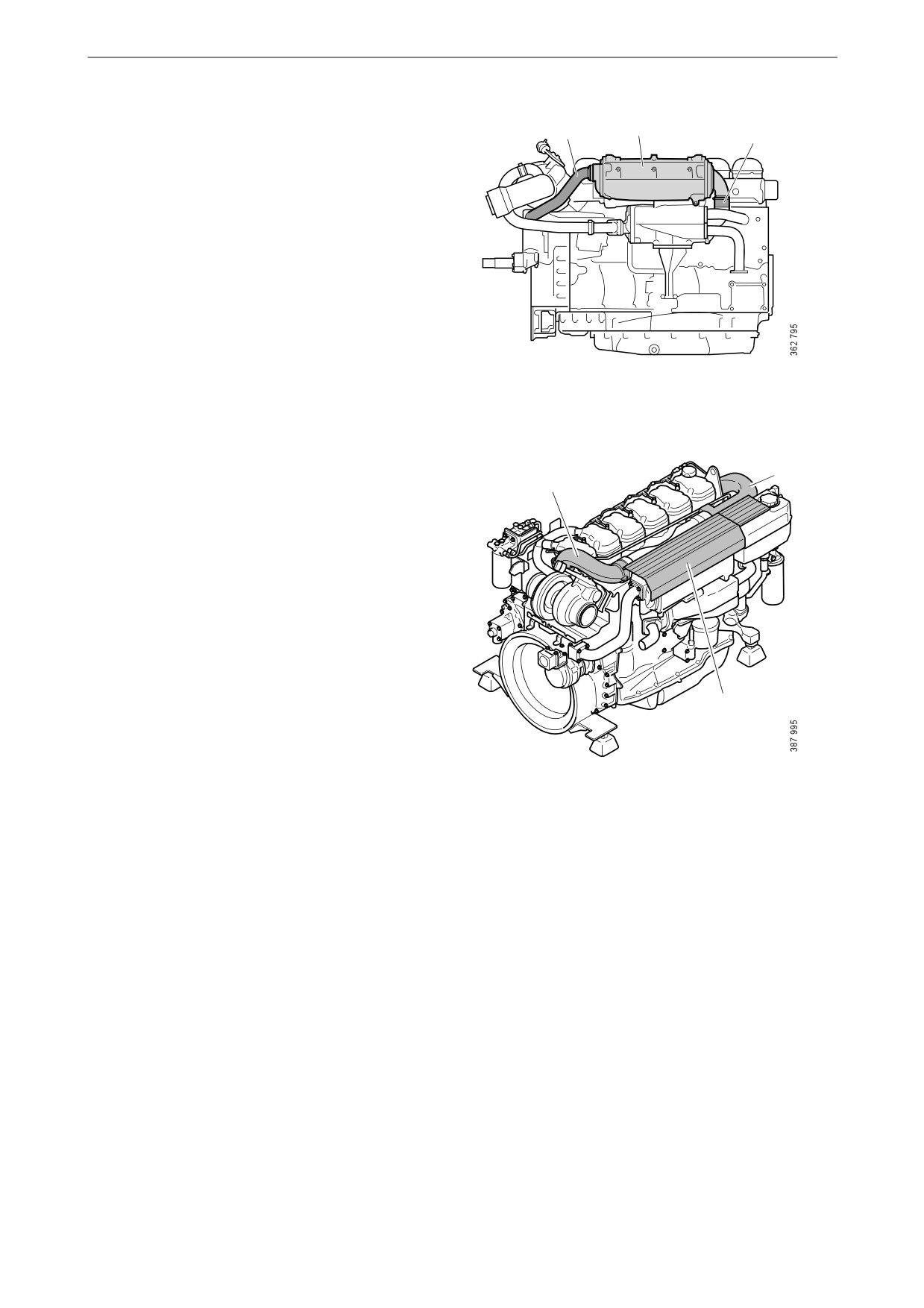
Removing the charge air cooler
3
When the cooler core of the charge air cooler
2
needs cleaning, the charge air cooler must be re-
moved if there is no space behind it to take out
the cooler core.
Before starting work: Make sure that the cooling
system is empty as described earlier.
1. Remove the protective plate (1) on the
charge air cooler.
2. Remove the charge air pipe (2) between the
charge air cooler and the turbocharger. Twist
the pipe to facilitate removal.
1
If the turbocharger has a wastegate valve and
the charge air pipe must be removed, the pipe
bracket must be removed and the pipe must
be turned 90° upwards before the hose and
the pipe are removed.
3. Remove the charge air pipe (3) between the
charge air cooler and the inlet pipe.
4. Remove the water pipe (4) of the charge air
cooler.
4
6
5
5. Release the hose clamp and remove the sea
water hose (5) between the charge air cooler
and the heat exchanger.
6. Remove the charge air cooler (6).
54
Cooling system
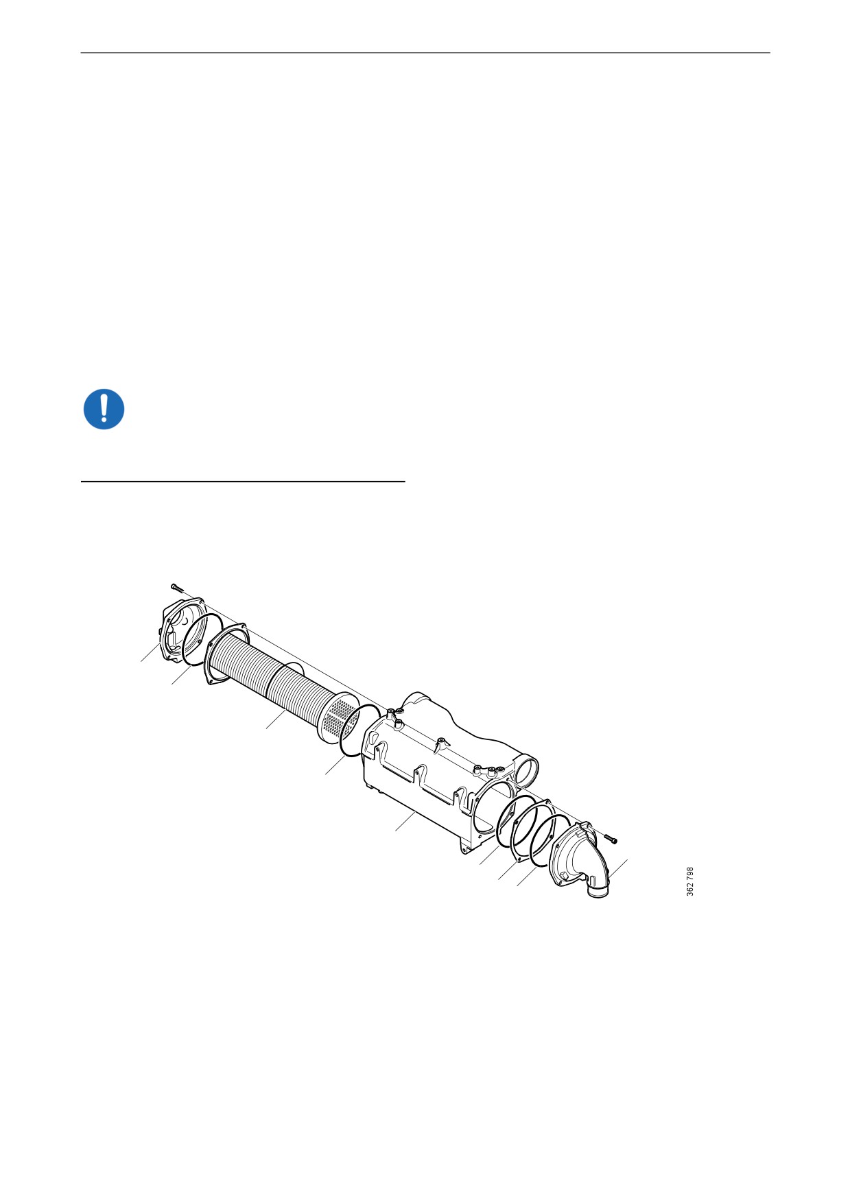
Cleaning the charge air cooler
The charge air cooler must be removed if there is
no space behind it to take out the cooler core. See
previous section.
1. Remove the screws on the charge air cooler
covers (1) and remove the covers. Mark the
covers so that you can put them back on the
correct side.
2. Press in the cooler core (3) slightly on one
side and pull it out from the other side.
3. Clean the cooler core on the outside with par-
affin-based engine detergent. Remove any
internal deposits using a round rod. Renew
the cooler core if it is damaged.
IMPORTANT!
Do not use caustic soda as this could damage the
aluminium.
4. Renew damaged or hard O-rings (2).
5. Assemble the charge air cooler. Tighten the
M8 screws on the covers to 15 Nm (11 lb-ft).
1
2
3
2
4
1
2
5
2
1. Cover.
2. O-rings.
3. Cooler core.
4. Charge air cooler housing.
5. Spacer.
55
Cooling system
Removing the heat exchanger
When the cooler core of the heat exchanger
needs cleaning, the heat exchanger must be re-
moved.
Before starting work: Make sure that the cooling
system is empty as described earlier.
1. Undo the V-clamp for the hose (1) between
2
4
3
the heat exchanger and the water-cooled ex-
2
1
haust pipe bend, if the engine has one. Bend
the hose to one side.
2. Remove the inlet and outlet coolant pipes
and the sea water pipe (2) from the heat ex-
changer.
3. Release the hose clamp and remove the sea
5
water hose (3) between the charge air cooler
and the heat exchanger.
4. Remove the screws holding the heat ex-
changer (4) in the two brackets.
5. Slacken the screws holding the heat ex-
changer bracket (5) in the cylinder block suf-
ficiently to allow the heat exchanger to be
removed.
6. Remove the heat exchanger.
56

Cooling system
Cleaning the heat exchanger
1. Remove the screws on the heat exchanger
covers (1) and remove the covers. Mark the
covers so that you can put them back on the
correct side.
2. Press in the cooler core (5) slightly on one
side and pull it out from the other side.
3. Clean the cooler core on the outside with par-
affin-based engine detergent. Remove any
internal deposits using a round rod. Renew
the cooler core if it is damaged.
IMPORTANT!
Do not use caustic soda as this could damage the
aluminium.
4. Renew damaged or hard O-rings (2).
5. Assemble the heat exchanger. Tighten the
M8 screws on the covers to 15 Nm (11 lb-ft).
1
2
2
3
5
2
1
2
4
1. Cover.
2. O-rings.
3. Spacer.
4. Heat exchanger housing.
5. Cooler core.
57

Cooling system
Fitting the heat exchanger
IMPORTANT!
There is a risk that the joint will crack if these in-
stallation instructions are not followed.
Tightening torque
M6
10 Nm (7 lb-ft)
M8
26 Nm (19 lb-ft)
M10
50 Nm (37 lb-ft)
1. Fit the heat exchanger (4) in place against the
2
4
3
brackets.
2
1
2. Fit the sea water hose (3) between the heat
exchanger and charge air cooler (use vase-
line if necessary) and tighten the hose clamp.
IMPORTANT!
5
To prevent leakage, a hose clamp with a safety
ring can be used.
3. Fit the screws (5 off) securing the heat ex-
changer without tightening them.
4. Tighten the screws securing the heat ex-
changer bracket (5) in the cylinder block.
5. First tighten the screw on the charge air cool-
er bracket and then the 4 screws on the heat
exchanger bracket.
6. Fit the inlet and outlet coolant pipes and the
sea water pipe from the heat exchanger (2).
7. Fit the hose (1) between the heat exchanger
and the water-cooled exhaust pipe bend and
tighten the V-clamp.
58
Cooling system
Fitting the charge air cooler
4
6
5
Tightening torque
M6
10 Nm (7 lb-ft)
M8
26 Nm (19 lb-ft)
M10
50 Nm (37 lb-ft)
1. Fit the charge air cooler (6) in place against
the brackets.
2. Fit the sea water hose (5) between the charge
air cooler and heat exchanger (use vaseline if
necessary) and tighten the hose clamp.
3. Fit the screws for the charge air cooler brack-
ets and tighten them.
4. Fit the water pipe (4) between the water
pump and the charge air cooler.
3
5. Fit the charge air pipe (3) between the intake
2
manifold and charge air cooler. To facilitate
fitting, lubricate the O-ring and the inside of
the connection in the charge air cooler with
vaseline. Press the charge air pipe straight to-
wards the charge air cooler while carefully
twisting the pipe to the right and left. Check
that the charge air pipe is properly fitted.
6. Fit the charge air pipe (2) between the charge
air cooler and turbocharger. To facilitate fit-
ting, lubricate the O-ring and the inside of the
connection in the charge air cooler with
1
vaseline. Press the charge air pipe straight to-
wards the charge air cooler while carefully
twisting the pipe to the right and left. Check
that the charge air pipe is properly fitted.
7. Fit the protective plate (1) on the charge air
cooler.
59
Cooling system
Internal cleaning: Removing oil and
grease in the cooling system
Environment
Use a suitable container. Used coolant must be
disposed of as specified in national and interna-
tional laws and regulations.
Always fit a new thermostat and a new cover to
the expansion tank after cleaning, as the oil in the
cooling system destroys the seals. If the engine is
equipped with a coolant filter, also renew this fil-
ter.
It may be necessary to wash it multiple times if
the cooling system is very dirty. One cause of
contamination can be that oil is lying on top of
the coolant and collecting high up in the cooling
system. If several rinses are needed, this is not
necessarily because work has been carried out
incorrectly. Oil residues often need to be rinsed
repeatedly from the expansion tank and the ex-
ternal heating system to be completely clean.
Repeated washing is more effective and prefera-
ble to using higher concentrations of detergent
(max. 10%) or cleaning for a longer period (max
30 minutes).
If only a small amount of dirt has collected in the
expansion tank after cleaning, one extra rinse
and clean of the expansion tank only is usually
sufficient. There is no need to clean the whole
cooling system again.
1. Run the engine until it has reached operating
temperature and then drain the cooling sys-
tem following the previous description.
2. Remove the thermostat.
60
Cooling system
3. Fill the cooling system with clean hot water
mixed with detergent 2 479 017. Detergent
2 479 017 must make up 5-10% (depending
on the degree of dirt) of the total coolant vol-
ume.
If detergent 2 479 017 is not available, use a
dishwasher detergent for household dish-
washers that does not foam. Concentration
1%.
4. Run the engine until it has reached operating
temperature for approximately 20-30 min-
utes. Remember to switch on the cab heating
system, if one is installed.
5. Drain the cooling system.
6. Fill the cooling system with clean, hot water
and run the engine for about 20-30 minutes.
7. Repeat steps 3-6 if the cooling system is not
clean.
8. Drain the water from the cooling system.
9. If necessary, clean the expansion tank by de-
taching all hoses and rinsing and cleaning
with a degreasing agent and a dishwashing
brush.
Alternatively, dismantle the expansion tank
and clean it with water with 10% of detergent
2 479 017. Fill the expansion tank with the
mixture, shake it and drain it. Renew the cov-
er of the expansion tank.
10. Fit a new thermostat.
11. Fill the cooling system with new coolant as
described in the next section.
12. Check again whether further dirt or oil has
collected in the expansion tank. Decide
whether it it is necessary to carry out another
full cleaning or whether only rinsing or
cleaning of the expansion tank will suffice.
61
Cooling system
Internal cleaning: Removing deposits
in the cooling system
Environment
Use a suitable container. Used coolant must be
disposed of as specified in national and interna-
tional laws and regulations.
1. Run the engine until it has reached operating
temperature and then drain the cooling sys-
tem following the previous description.
2. Remove the thermostat.
3. Fill the cooling system with clean, hot water
mixed with radiator detergent which is based
on sulphamic acid and contains dispersing
agents. Follow the manufacturer's instruc-
tions for the concentration and cleaning peri-
od.
4. Run the engine for the specified time. Re-
member to switch on the cab heating system,
if one is installed.
5. Drain the cooling system.
6. Fill the cooling system with clean, hot water
and run the engine for about 20-30 minutes.
7. Drain the water from the cooling system.
8. Reinstall the thermostat.
9. Fill the cooling system with new coolant as
described in the next section.
62

Cooling system
Filling coolant
This procedure applies when the cooling system
has been drained and needs to be filled with a
large amount of coolant.
Special tool
Number, designation
Illustration
2 443 679, coolant
pump
WARNING!
Use protective gloves as coolant can cause irrita-
tion if it comes in contact with the skin. Hot cool-
ant can also cause scalding.
IMPORTANT!
Mix the coolant as specified in the section head-
ed Coolant.
It is not permissible to top up large amounts of
coolant via the expansion tank. Filling via the ex-
pansion tank leads to air locks in the cooling sys-
tem which can lead to e.g. damage to the coolant
pump shaft seal. If a large amount of coolant
needs to be added, follow the instructions in the
section Filling coolant.
Never fill a large amount of cold coolant in a hot
engine. There is great risk of cracks forming in
the cylinder block and cylinder heads.
Do not start the engine until the correct coolant
level has been obtained. If the engine is started
with an insufficient coolant level, it can damage
the coolant pump shaft seal, which leads to cool-
ant leakage.
63