Scania Marine engine. DI13 XPI. Operator’s manual - part 3
Lubrication system
Checking the oil level
2
REQUIREMENT!
Leave the engine off for at least 7 minutes before
you check the oil level.
If the oil level exceeds the maximum level, the
oil must be changed. Check the cause if the oil
level exceeds the maximum level and contact
your nearest workshop with qualified personnel
if you suspect a fault.
2
1
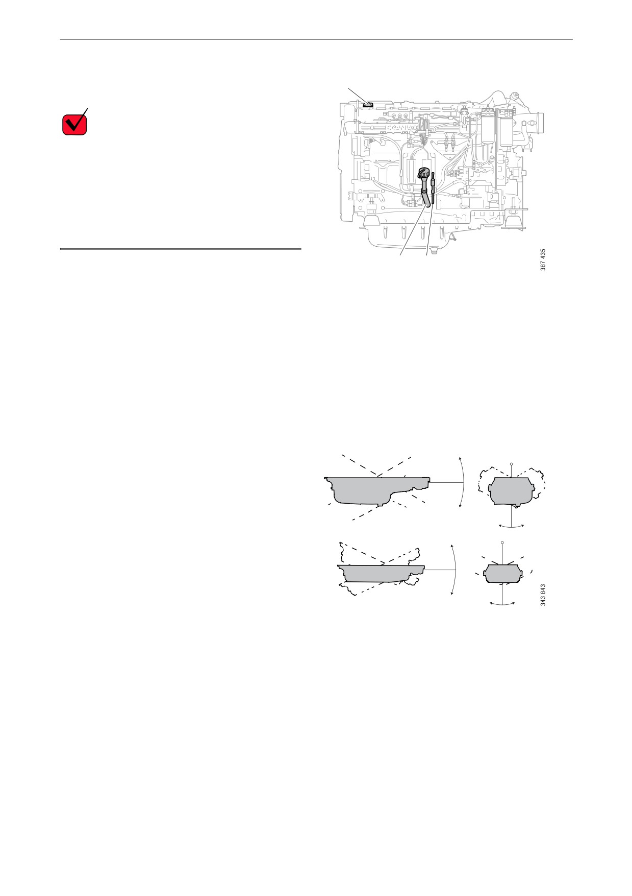
1. Remove the oil dipstick (1) and check the oil
level. The correct level is between the mini-
1. Oil dipstick.
mum and maximum marks on the oil dip-
2. Oil filler.
stick.
2. Fill with more oil at point 2 in the illustration
when the oil level is at or below the lower
mark.
You can find more information on the cor-
rect oil grade under the heading Oil grade.
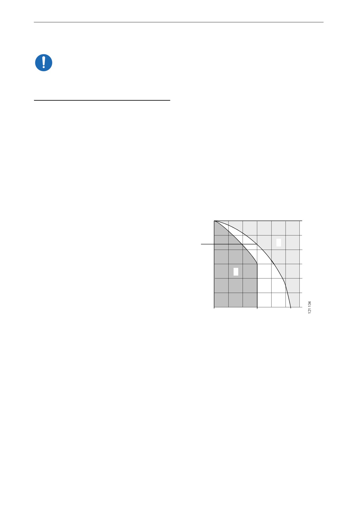
Maximum angles of inclina-
tion during operation
30°
Maximum permissible angles of inclination dur-
ing operation vary, depending on the type of oil
30°
sump. See illustration.
30°
30°
25°
25°
30°
30°
32
Lubrication system
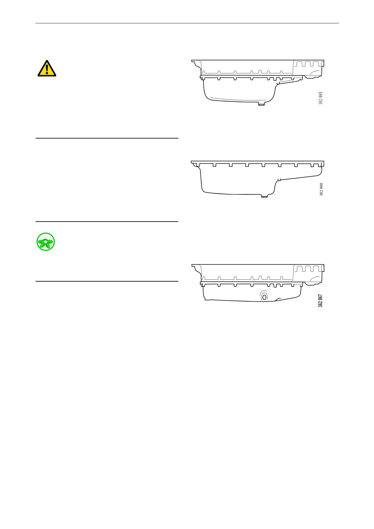
Changing the oil
WARNING!
Hot oil can cause burns and skin irritation. Wear
protective gloves and eye protection when
changing hot oil. Make sure that there is no pres-
sure in the lubrication system before changing
the oil. The oil filler cap must always be in place
Oil volume:
when starting and running the engine to prevent
Min. 39 litres (10.3 US gallons).
oil being ejected.
Max. 45 litres (11.9 US gallons).
Note:
Change oil more often if the engine is subjected
to particularly demanding operation, such as a
dusty environment, or if deposits on the paper in
the centrifugal oil cleaner are thicker than 28 mm
(1.1 in).
Renew the oil filter and clean the centrifugal oil
Oil volume:
cleaner when changing oil.
Min. 30 litres (7.9 US gallons).
Max. 36 litres (9.5 US gallons).
Environment
Use a suitable container. Used oil must be dis-
posed of as specified in national and internation-
al laws and regulations.
1. Unscrew the oil plug and drain the oil when
the engine is hot. In certain engine types the
Oil volume:
oil is pumped out by means of a bilge pump.
Min. 28 litres (7.4 US gallons).
If the engine is drained via the valve, the oil
should be hot. Alternatively, use a pump.
Max. 34 litres (9.0 US gallons).
This so that draining occurs more quickly.
2. Wipe off the magnet on the oil plug.
3. Renew the gasket on the oil plug.
4. Refit the oil plug.
5. Fill with the amount of oil specified for the
oil sump.
6. Wait at least 7 minutes.
7. Check the level on the oil dipstick.
33
Lubrication system
Cleaning the centrifugal oil
cleaner
WARNING!
The oil may be hot. Carefully remove the cover
from the centrifugal oil cleaner.
Use eye protection and protective gloves when
working on the centrifugal oil cleaner.
When the centrifugal oil cleaner is cleaned, there
should be some dirt deposits on the paper in the
rotor cover. If the paper is clean, the equipment
is not working as it should. If this is the case, in-
vestigate the cause of this.
Renew the paper more frequently if the dirt de-
posits are thicker than 28 mm (1.1 inches) during
a scheduled oil change.
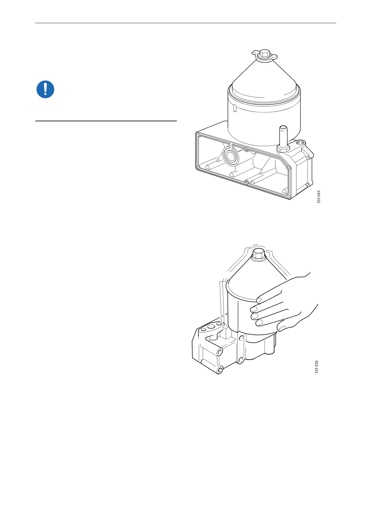
1. Clean the cover.
2. Unscrew the nut securing the outer cover.
3. Let the oil run out from the rotor.
x 1.5
4. Lift out the rotor. Wipe off the outside.
5. Loosen the rotor nut and unscrew it approx.
1.5 turns.
Note:
Take care not to damage the rotor shaft.
34
Lubrication system
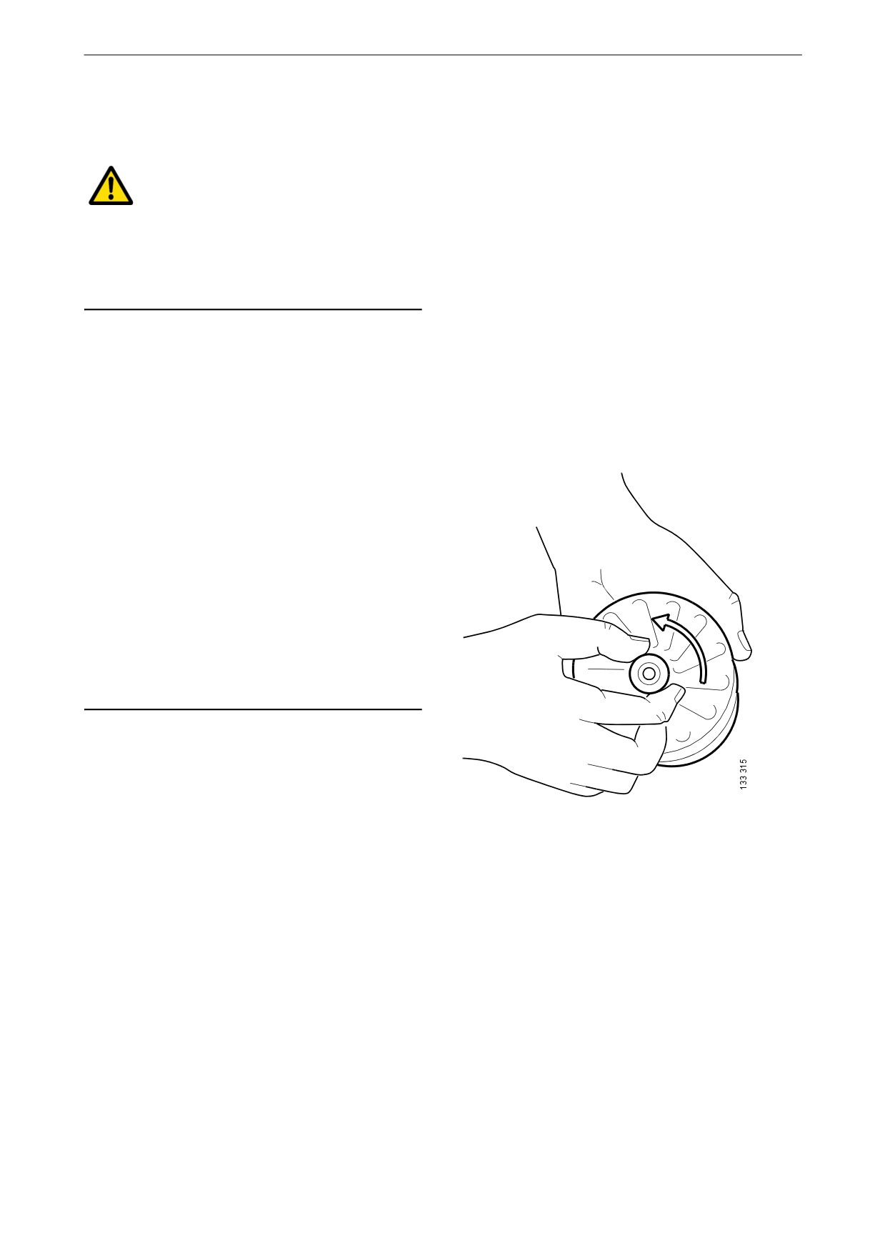
6. If the rotor nut is jammed: Turn the rotor up-
side down and fasten the rotor nut in a vice.
See illustration.
7. Use protective jaws so as not to damage the
M20
grooves of the rotor nut.
8. Turn the rotor 1.5 turns anti-clockwise by
hand.
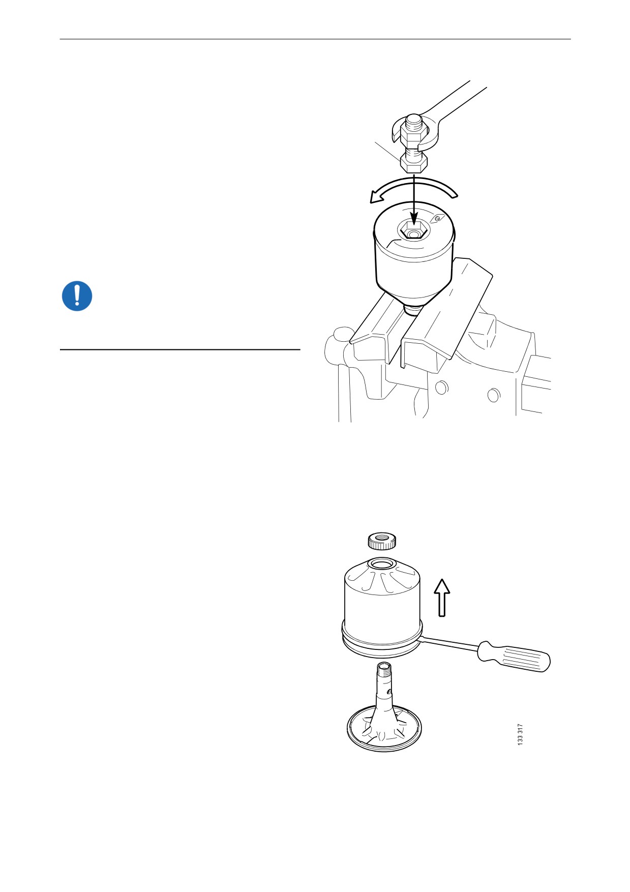
9. If this does not work: Screw two nuts togeth-
er with an M20 screw.
10. Position the screw head at the bottom of the
x 1.5
rotor.
11. Position a ring spanner on the lower nut and
turn the rotor 1.5 turns anti-clockwise.
IMPORTANT!
Do not attach the rotor directly to the vice. Never
strike the rotor cover.
12. Remove the rotor cover by holding the rotor
in both hands and tapping the rotor nut
against the table. Never strike the rotor di-
rectly as this may damage its bearings.
13. Remove the strainer from the rotor cover. If
the strainer is stuck, insert a screwdriver be-
tween the rotor cover and strainer and care-
fully prise them apart.
35
Lubrication system
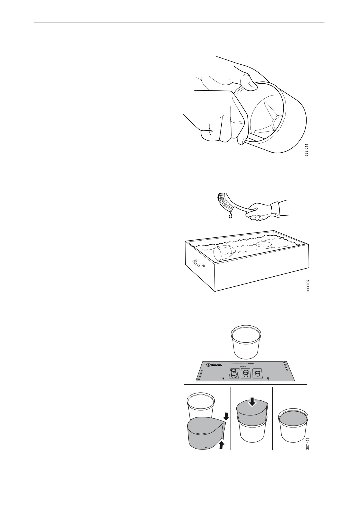
14. Remove the paper insert.
15. Scrape off any remaining dirt deposits from
the inside of the rotor cover. If the deposits
on the paper are thicker than 28 mm (1.1 in),
the centrifugal oil cleaner must be cleaned
more often.
16. Wash the parts according to the applicable
industrial method.
17. Inspect the 2 nozzles on the rotor. Ensure that
they are not blocked or damaged.
Renew any damaged nozzles.
18. Check that the bearings are undamaged.
Renew damaged bearings.
1
19. Fold and fit a new paper insert on the inside
of the rotor cover as illustrated.
2
3
4
36

Lubrication system
20. Fit the strainer onto the rotor.
21. Fit a new O-ring to the foot of the centrifugal
oil cleaner.
22. Refit the rotor cover. Ensure that the O-ring
is not outside the edges, but is in the groove.
23. Screw the rotor nut back on by hand.
24. Check that the shaft is not damaged or loose.
Contact a workshop with qualified personnel
if the rotor shaft needs to be renewed.
Note:
Take care not to damage the rotor shaft.
25. Refit the rotor and rotate it by hand to make
sure it rotates easily.
37
Lubrication system
26. Fit a new O-ring in the cover.
27. Refit the cover and tighten the lock nut.
Tightening torque 20 Nm (15 lb-ft).
IMPORTANT!
To reduce the risk of oil leakage it is important to
tighten the cover to the correct tightening torque.
Operational testing of the
centrifugal oil cleaner
Operational testing need only be carried out if it
is suspected that the centrifugal oil cleaner is
malfunctioning. For example, if there are unusu-
ally few deposits given the distance driven.
1. Run the engine until it reaches normal oper-
ating temperature.
2. Turn off the engine and listen for the sound
from the rotor. It should continue rotating for
a time, even when the engine has stopped.
3. Use your hand to feel if the filter housing is
vibrating.
4. If the filter housing is not vibrating, disman-
tle and check the centrifugal oil cleaner.
38
Lubrication system
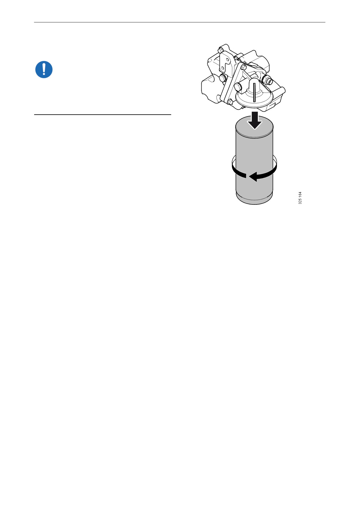
Renewing the oil filter
IMPORTANT!
Clean the centrifugal oil cleaner at the same time
as you change the oil filter. Otherwise, the oil fil-
ter will become clogged and the oil will pass the
filter without being cleaned.
1. Remove the old filter.
2. Oil the rubber gasket on the new filter.
3. Fit the new filter and tighten it by hand. Nev-
er use tools because the filter could sustain
damage, obstructing circulation.
4. Start the engine and check for leaks.
39

Air cleaner
Air cleaner
WARNING!
3
Never start the engine without the air filter in po-
sition. Without the air filter, there is a risk of dirt
2
being sucked into the engine.
The engine turbocharger will continue to rotate
1
and take in air for a time, even after the engine
has stopped. Therefore, wait for a few minutes
before opening the air cleaner.
IMPORTANT!
4
Renew the filter element earlier than the mainte-
nance interval if the vacuum indicator shows red.
5
The filter element must not be cleaned in water
or be blown clean with compressed air. There is
Air cleaner with safety cartridge.
always a risk that the filter element will be dam-
1. Filter element.
aged when it is cleaned.
2. O-ring.
3. Vacuum indicator.
4. Safety cartridge.
5. Cover.
2
1
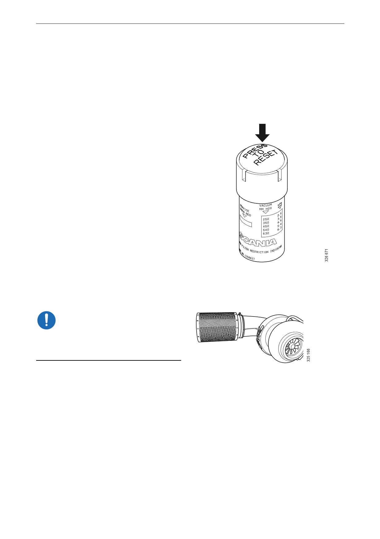
Reading the vacuum indicator
If the vacuum indicator's red plunger is fully vis-
ible, renew the air cleaner filter element in ac-
3
4
cordance with the following section.
Air cleaner without safety cartridge.
1. Filter element.
2. Vacuum indicator.
3. O-ring.
4. Cover.
40
Air cleaner
Renewing the air cleaner filter
element and safety cartridge
1. Remove the cover from the air cleaner.
2. Renew the filter element.
3. If the air cleaner has a safety cartridge: Re-
move the safety cartridge and fit a new one.
4. Insert a torch into the filter element and
check that the filter paper is free of holes and
cracks.
5. Renew the O-ring if it is damaged or hard.
6. Assemble the air cleaner.
7. Ensure that the O-ring is not outside the edg-
es.
8. Reset the vacuum indicator by pressing in
the button marked in the illustration.
Renewing an air filter with a
non-renewable element
IMPORTANT!
If the engine has an air filter with a non-renewa-
ble Scania element, it should be renewed instead
of cleaned.
Air filter with a non-renewable element.
41
Cooling system
Antifreeze and corrosion protection
Cooling system
The antifreeze and corrosion protection used in
Scania engines should be antifreeze (ethylene
Coolant
glycol) and corrosion inhibitor.
Note:
Only Scania coolant or another product with
The coolant should be changed when the cooling
functioning antifreeze and corrosion protection
system is cleaned: every 6,000 hours or at least
may be used in Scania engines. Products not ful-
every 5 years. See Changing the coolant and
filling the demands in this section may lead to
cleaning the cooling system.
faults and damage occurring in the cooling sys-
tem. This can lead to the invalidation of Scania's
warranty for faults and damage caused by the use
The coolant recommended by Scania is a mix-
of inappropriate coolant.
ture of water with antifreeze (ethylene glycol)
and corrosion inhibitor. The coolant has several
Addition of antifreeze and corrosion
characteristics which are important for the oper-
inhibitor to water
ation of the cooling system:
The coolant should contain 35-55% by volume
• Corrosion inhibitor.
antifreeze (ethylene glycol) and corrosion inhib-
itor. The percentage varies depending on the
• Antifreeze.
need for antifreeze.
• Increases the boiling point.
A minimum of 35% by volume of Scania anti-
Water
freeze and corrosion inhibitor is needed to pro-
vide sufficient protection against corrosion.
Use only pure fresh water that is free from parti-
cles, sludge and other impurities. If there is un-
Note:
certainty about the quality of the water, Scania
Too high a dose of antifreeze and corrosion in-
recommends use of Scania ready-mixed cool-
hibitor will increase the amount of sludge and
ants. See the section Recommended Scania prod-
blockages accumulating in the radiator. Too low
ucts.
a concentration can lead to corrosion of the cool-
ing system and ice formation at low tempera-
tures.
Measure the ethylene glycol content (antifreeze
and corrosion protection) with a refractometer
following the instructions in the Checking cool-
ant antifreeze and corrosion protection section.
42
Cooling system
Risk of freezing
IMPORTANT!
The engine should not be subjected to heavy
loads when ice starts to build up in the cooling
system.
As the coolant starts to freeze, the water in the
coolant starts to crystallise and the percentage of
ethylene glycol in the coolant therefore rises. If
freezing produces a great increase in the amount
of ice, circulation problems could arise. There is
no risk of damage by freezing if the content of
Scania antifreeze and corrosion inhibitor, or an
equivalent mixture of a similar product, is at
least 35% by volume.
Minimal ice formation in the coolant sometimes
causes minor problems without any risk of dam-
age. For example, the auxiliary heater may not
work for up to 1 hour after the engine has been
started.
10
20
30
40
50
60%
The chart depicts coolant properties at different
o
percents of antifreeze and corrosion inhibitor
-10
C
concentration by volume.
o
-16
C
1
o
-20
C
Curve A: Ice formation starts (ice slush)
o
-30
C
Curve B: Damage by freezing
3
2
o
Area 1: Safe range
-40
C
Area 2: Malfunctions may occur (ice
o
-50
C
slush)
o
Area 3: Risk of damage by freezing
-60
C
B
A
The following example shows coolant properties
with 30 percent by volume of antifreeze and cor-
rosion inhibitor:
• Ice slush starts to form at -16°C (3°F).
• At -30°C (-22°F), there is a risk of cooling
system malfunction.
• There is no risk of damage by freezing with a
minimum antifreeze and corrosion inhibitor
content of 35 percent by volume.
Example: If the temperature is -16°C (3°F), there
is a risk of damage by freezing if the percentage
of antifreeze and corrosion inhibitor is 20% by
volume. At 30% antifreeze and corrosion protec-
tion by volume the coolant will not contain any
ice.
43
Cooling system
Hot climates
In order to retain the corrosion protection and the
higher boiling point, it is essential to use coolant
consisting of water mixed with antifreeze and
corrosion inhibitor (ethylene glycol). This also
applies in countries where the temperature never
drops below 0°C (32°C).
The coolant should always contain 35-55% by
volume of antifreeze and corrosion inhibitor so
that the coolant properties ensure that the coolant
works correctly.
Topping up
Coolant must only be topped up with pre-mixed
coolant. The pre-mixed coolant can either be
concentrate mixed with clean freshwater or pre-
mixed coolant from the factory. Use only pure
fresh water that is free from particles, sludge and
other impurities.
IMPORTANT!
Containers, which are used for mixing coolant,
must be intended for the purpose and free from
any dirt or contaminants. When the containers
not in use they must be kept closed to avoid col-
lecting dirt and dust.
Note:
Within the coolant change interval, coolant may
only be reused if it has been cleaned of dirt,
sludge and particles. If the coolant is contaminat-
ed with oil or fuel, it must not be reused.
44

Cooling system
Recommended Scania products
Scania Ready Mix 50/50
Scania Ready Mix 50/50 is a ready-mixed cool-
ant containing 50 % antifreeze (ethylene glycol)
and corrosion protection and 50 % water. It
should be used in cold countries where there is a
risk of freezing in the cooling system.
Part no.
Volume
Volume
litres
US gallons
1 921 955
5
1.3
1 921 956
20
5.3
1 921 957
210
55
1 896 695
1,000
264
Scania Ready Mix35/65
Scania Ready Mix 35/65 is a ready-mixed cool-
ant containing 35% antifreeze (ethylene glycol)
and corrosion protection and 65% water. It
should be used in warm countries where there is
no risk of freezing in the cooling system.
Part no.
Volume
Volume
litres
US gallons
2 186 291
5
1.3
2 186 292
20
5.3
2 186 293
210
55
2 186 294
1,000
264
Scania concentrate
Scania also produces coolant with antifreeze and
corrosion inhibitor in the form of a concentrate.
Part no.
Volume
Volume
litres
US gallons
1 894 323
5
1.3
1 894 324
20
5.3
1 894 325
210
55
1 894 326
1,000
264
45
Cooling system
Antifreeze and corrosion protection
concentration table, litres
35% by volume of Scania antifreeze provides
sufficient protection against corrosion.
Example:
• The total volume of the cooling system is 40
litres.
• The measured concentration of ethylene gly-
col is 35% by volume (freezing point -21°C).
According to the table there are 14 litres of
ethylene glycol in the cooling system.
• The required concentration of ethylene glycol
is 45% by volume (freezing point -30°C). Ac-
cording to the table, 18 litres of ethylene gly-
col are required in the cooling system.
• Since there are already 14 litres in the cooling
system, 4 litres of ethylene glycol must be
added to the cooling system (18 - 14 = 4 li-
tres).
Adequate protection against corrosion
Volume of ethylene glycol (%)
35
40
45
50
60
Cooling system volume
Ice slush forms (°C)
-21
-24
-30
-38
-50
(litres)
11
12
14
15
18
30
14
16
18
20
24
40
18
20
23
25
30
50
21
24
27
30
36
60
25
28
32
35
42
70
28
32
36
40
48
80
32
36
41
45
54
90
35
40
45
50
60
100
39
44
50
55
66
110
Volume of ethylene glycol (litres)
42
48
54
60
72
120
46
52
59
65
78
130
49
56
63
70
84
140
53
60
68
75
90
150
56
64
72
80
96
160
60
68
77
85
102
170
63
72
81
90
108
180
67
76
86
95
114
190
70
80
90
100
120
200
46
Cooling system
Antifreeze and corrosion protection
concentration table, US gallons
35% by volume of Scania antifreeze provides
sufficient protection against corrosion.
Example:
• The total volume of the cooling system is
10.6 US gallons.
• The measured concentration of ethylene gly-
col is 35% by volume (freezing point -6 °F).
According to the table there are
3.7 US gallons of ethylene glycol in the cool-
ing system.
• The required concentration of ethylene glycol
is 45% by volume (freezing point -22 °F). Ac-
cording to the table, 4.8 US gallons of ethyl-
ene glycol are required in the cooling system.
• Since the cooling system already contains
3.7 US gallons, fill another 1.1 US gallons of
ethylene glycol in the cooling system (4.8 -
3.7 = 1.1 US gallons).
Adequate protection against corrosion
Volume of ethylene glycol (%)
35
40
45
50
60
Cooling system volume
Ice slush forms (°F)
-6
-11
-22
-36
-58
(US gallons)
2.9
3.2
3.7
4
4.8
7.9
3.7
4.2
4.8
5.3
6.3
10.6
4.8
5.3
6.1
6.6
7.9
13.2
5.5
6.3
7.1
7.9
9.5
15.9
6.6
7.4
8.5
9.2
11.1
18.5
7.4
8.5
9.5
10.6
12.7
21.1
8.5
9.5
10.8
11.9
14.3
23.8
9.2
10.6
11.9
13.2
15.9
26.4
Volume of ethylene glycol (US gal-
10.3
11.6
13.2
14.5
17.4
29.1
lons)
11.1
12.7
14.3
15.9
19
31.7
12.2
13.7
15.6
17.2
20.6
34.3
12.9
14.8
16.6
18.5
22.2
37
14
15.9
18
19.8
23.8
39.6
14.8
16.9
19
21.1
25.4
42.3
15.9
18
20.3
22.5
26.9
44.9
16.6
19
21.4
23.8
28.5
47.6
17.7
20.1
22.7
25.1
30.1
50.2
18.5
21.1
23.8
26.4
31.7
52.8
47