Scania DC13 PDE. Industrial engine en-GB 2 823 973. Operator’s manual - part 5

Other
WARNING!
Block the starting device. If the engine starts un-
expectedly, there is a serious risk of injury.
IMPORTANT!
The engine must be cold when the work is car-
ried out.
Remember to remove the turning tool from the
flywheel after adjustment.
Note:
Carry out the working without pausing, so that
no step is overlooked.
Carry out a check and adjustment of the valve
clearances and the unit injectors one more time
after the first 500 hours of operation. After this,
adjustment according to the regular interval
takes place, which is every 2,000 operational
Upper and lower window to read the engraving on
hours.
the flywheel.
The reference information UP TDC, DOWN
TDC and the angle indications listed in the table
below are engraved on the flywheel. Depending
on the engine installation, this information is vis-
ible in one of the windows, either furthest up or
furthest down on the flywheel. See illustration.
1
2
3
4
5
6
Order of cylinders.
64

Other
Workflow table
Adjust valves and injectors according to the table
below. Follow the respective column depending
on whether you are reading the engraving on the
flywheel in the lower or the upper window. Start
adjustment at the top of the table.
Reading in the low-
Valve transition on
Adjust valves on
Adjust injector on
Reading in the up-
er window
cylinder
cylinder
cylinder
per window
DOWN TDC
1
6
2
UP TDC
120/480
5
2
4
300/660
240/600
3
4
1
60/420
DOWN TDC
6
1
5
UP TDC
120/480
2
5
3
300/660
240/600
4
3
6
60/420
65
Other
Checking and adjusting the valve
clearance
Valve clearance, specifications
Intake valve
0.45 mm (0.018 in)
Exhaust valve
0.70 mm (0.028 in)
Tightening torque
Lock nut for valves
35 Nm (26 lb/ft)
1. Clean the rocker covers and the area around
them.
2. Remove the rocker covers.
3. Use the turning tool appropriate to the instal-
lation of the engine. Tool 99 309 is used to
rotate the flywheel from the underside of the
engine and tool 2 402 509 is used from the
top side.
4. Start adjusting one cylinder according to the
table. Rotate the flywheel until the correct
engraving can be read on the flywheel. It
may be necessary to rotate it more than 1 rev-
olution.
Rotate the flywheel in the rotational direc-
tion of the engine, which is clockwise
viewed from the front of the engine and anti-
3
clockwise viewed from the back of the en-
gine.
During a valve transition, the exhaust valve
(the long arm) is closing at the same time as
4
the intake valve is opening.
The UP TDC engraving on the flywheel is
now visible in the window furthest up on the
flywheel. The DOWN TDC engraving is vis-
5
ible in the lower window.
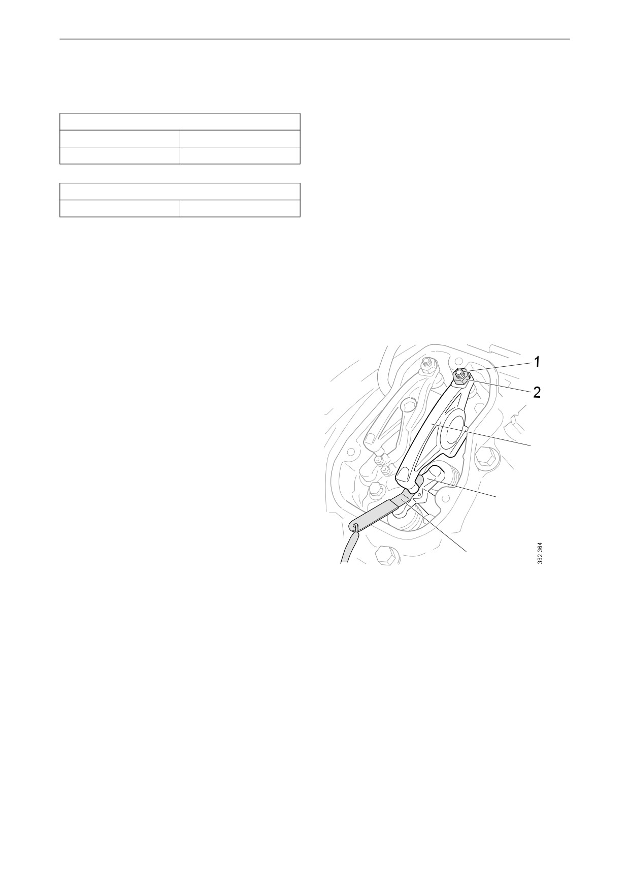
1. Adjusting screw.
5. Read Workflow table on the previous page to
2. Lock nut.
see which valve to adjust.
6. Stick the feeler gauge under the pressure pad
3. Rocker arm.
of the rocker arm and check the valve clear-
4. Valve bridge.
ance.
5. Feeler gauge.
7. If necessary, adjust the valve clearance by
a) loosening the lock nut on the end of the
rocker arm
b) adjusting the valve clearance with the ad-
justing screw
c) tightening the lock nut.
8. Mark the rocker arm with the felt-tip pen and
adjust the unit injector according to the next
section. Then continue on to the next cylin-
der according to the table.
66

Other
Checking and adjusting the unit in-
jectors
Tightening torque
Lock nut for unit injec-
39 Nm (29 lb/ft)
tors
1. See the Workflow table for details of the in-
jectors to be adjusted.
2. Fit the setting tool with the metal plate
around the unit injector.
The unit injector is correctly set when the
3
2
small piston (1) is level with the flat upper
surface of the tool. Use a finger to check.
You can feel very small differences. See also
the illustrations on the next page.
3. If necessary, adjust the unit injector by
a) loosening the lock nut (2)
b) adjusting the unit injector using the adjust-
ing screw (3)
c) tightening the lock nut.
IMPORTANT!
Remove the setting tool when the adjustment is
done.
4. Mark the injector with the felt-tip pen and
1
continue adjustment according to the table.
67

Other
The setting tool piston is above or below the flat
The setting tool piston is level with the flat upper
upper surface of the tool. Adjust the unit injector. surface of the tool. The unit injector is correctly
adjusted.
68

Quality requirements for fuel
Quality requirements for
fuel
Quality requirements and testing standards for
the most important properties of different types
of fuel are described in the Workshop Manual.
This can be ordered from Scania dealers or di-
rectly from Scania.
Diesel
Properties
The quality of the diesel is very important for the
operation and service life of the engine and the
fuel system, and also for the engine performance.
REQUIREMENT!
The diesel should comply with the requirements
of European standards EN590 or EN15940.
However, Scania accepts larger tolerances of
certain properties. Please see the table below.
Properties
Requirements
Viscosity at 40°C
1.4-4.5 cSt
(104°F)
Density at 15°C (59°F)
0.79-0.87 kg/dm3
Ignitability (CET rating)
minimum 49
Lowest flashpoint
56°C (132°F)
Particulate contamina-
Classification 22/20/17
tion level
according to ISO 4406
69

Quality requirements for fuel
Permitted sulphur content in diesel
IMPORTANT!
The operator is responsible for using the correct
type of diesel to ensure that local laws are com-
plied with.
Engine type
Max. sulphur content
Remark
Engines without EGR sys-
4,000 ppm (0.4%)
If the sulphur content is higher than 2,000 ppm, the
tem
oil change intervals must be halved. A higher sul-
phur content than 4,000 ppm is not permitted, since
this will result in engine damage.
Engines with EGR system
350 ppm (0.035%)
If diesel with too high a sulphur content is used,
this causes engine damage.
Temperature dependence of diesel
IMPORTANT!
Mixing kerosene or other paraffins with the die-
sel is prohibited. The injectors may be damaged.
It is not permissible to mix petrol with diesel. In
the long term petrol can cause wear in the injec-
tors and engine.
At temperatures lower than those specified for
the diesel, paraffin wax may precipitate from the
diesel and block filters and pipes. The engine can
then lose power or stop.
The diesel is adapted for use in the specific cli-
mate of each country. If an engine is to be oper-
ated in a temperature zone with a temperature
lower than normal, first identify the temperature
properties of that particular diesel.
70
Quality requirements for fuel
Use of fuel oil in stand-by generator sets
Long-term storage of diesel, where the diesel
comes into contact with water, may lead to the
growth of micro organisms (bacteria and fun-
gus). To avoid this in fuel used in stand-by gen-
erator sets, Scania permits the use of fuel oil
according to DIN 51603-1 and
ÖNORM C 1109.
Use of fuel oil is only permitted for stand-by
generator sets and under the following condi-
tions:
• The fuel must not be stored or used in temper-
atures under -10°C (14°F).
• The engine must not be equipped with an
SCR system.
71
Quality requirements for fuel
Biodiesel (FAME)
Use of biodiesel
IMPORTANT!
Engine types DC16 084A and DC16 091A are
approved for used with biofuel in accordance
with ASTM D7467 (up to 20% mixture of bio-
diesel).
For other engines, a maximum of 10% mixture
of biodiesel should be used.
Note that reduction of maintenance intervals ap-
plies for use of more than 10% biodiesel.
Scania uses the term biodiesel to refer to a re-
newable diesel made from greases or oils and
methanol. The biodiesel should conform to the
requirements of European standard EN 14214 or
Brazilian standard ANP-45. For biodiesel in ac-
cordance with EN 14214 or ANP-45, the generic
term FAME is frequently used.
Normal diesel in accordance with EN 590 can
contain up to 7% biodiesel from the diesel sup-
plier. There are grades of diesel that comply with
EN 590 but contain a higher mixture of biodies-
el.
For PDE engines, Scania approves the use of up
to 100% biodiesel in accordance with EN 14214
or ANP-45.
Maintenance interval
IMPORTANT!
Make sure that maintenance intervals are differ-
ent when operating on diesel or biodiesel.
With a greater mixture of biodiesel than 10%, the
renewal intervals for the following are halved:
• Fuel filter.
• Oil filter.
• Engine oil.
The viscosity grade of the engine oil should be
xW-40. xW-30 grade oils are unsuitable due to
the fuel dilution effect.
The engine oil level must be checked regularly.
If the oil level exceeds the maximum level, the
oil must be changed.
72
Quality requirements for fuel
The water separating prefilter must be checked
regularly in order to prevent water ingress into
the fuel system.
When using biodiesel, the EGR cooler may also
need to be cleaned.
Storage of biodiesel
IMPORTANT!
Biodiesel must not be stored for more than 6
months.
Biodiesel has a maximum storage life of
6 months from the date of production to the ex-
piry date. The fuel is affected by light, tempera-
ture, water, etc. during storage, which affects the
fuel characteristics and durability.
Biodiesel also has lower stability against oxida-
tion than diesel. This can result in a thickening of
the fuel and blocking of parts of the fuel system,
e.g. the fuel filter. Bacterial growth can occur
when biodiesel is stored in a tank in unfavoura-
ble conditions. Avoid storage in barrels or auxil-
iary tanks, except when fuel turnover rates are
high. Check tank cleanliness whenever refuel-
ling takes place.
If the engine has been refuelled with biodiesel,
and is stationary for a long period, condensation
water can form in the fuel tank resulting in bac-
terial growth.
See also the section Preservative fuel.
73
Quality requirements for fuel
HVO
HVO is a synthetic diesel which is manufactured
through the hydrogenation of plants and animal
fats. To the user, HVO is reminiscent of diesel in
accordance with EN590, apart from HVO having
a somewhat lower density.
Scania approves the use of up to 100% HVO for
all engines in accordance with the European
standard EN 15940.
GTL
GTL is a synthetic fuel that is often refined from
natural gas. To the user, GTL is reminiscent of
diesel in accordance with EN590, apart from
GTL having a somewhat lower density and less
odour.
Scania approves the use of up to 100% GTL in
accordance with the European standard EN
15940.
74
Preparing the engine for storage
Preparing the engine for
storage
If the engine is not being used for an extended
period its cooling system, fuel system and com-
bustion chamber and outside must be protected
against rust.
The engine can normally stand idle for up to
6 months without needing preparation. For
longer periods of than 6 months, however, the
measures in the following sections must be tak-
en. These measures provide protection for ap-
proximately 3 years, then the preparing
procedure must be repeated. An alternative to
preparing the engine for long-term storage is to
start the engine and warm it up every 6 months.
Preparation means that the following measures
are taken:
• The engine is cleaned thoroughly.
• Run the engine for a specific period using
special preservative fuel, oil and coolant.
• Otherwise prepare the engine for storage (fil-
ter renewal, lubrication, etc.).
Preservative products
Preservative oil
Use a normal engine oil that meets the require-
ments in the Oil grade section.
75
Preparing the engine for storage
Preservative coolant
Use coolant containing 50% by volume of gly-
col. Example: BASF MPG Glysacorr P113 and
Valvoline Zerex P113 FP.
WARNING!
Ethylene glycol can be fatal if ingested and can
cause skin irritation and eye damage.
Preservative fuel
Preservative fuel must not contain biodiesel.
Even small amounts of 5-10% biodiesel can have
adverse effects on the engine when in longterm
storage.
Long-term storage of diesel, where the diesel
comes into contact with water, may lead to the
growth of micro organisms (bacteria and fun-
gus).
In order to minimise the growth of micro-organ-
isms, preservative fuel should contain the fol-
lowing additives. The additives should be
selected and added by the fuel supplier.
Preservative fuel should comply with the follow-
ing requirements:
•
0% biodiesel.
•
Max. sulphur content 50 ppm.
•
Max. water content 200 ppm.
•
The fuel must contain additives to stop the
growth of micro-organisms.
76
Preparing the engine for storage
Preparations for storage
Environment
Use a suitable container. Used oil and coolant
must be disposed of as specified in national and
international laws and regulations.
Note:
Do not remove the injectors.
1. Remove plugs and tape from the coolant
connections, air intake and exhaust pipe.
2. Drain the oil.
3. Renew the oil filter and fuel filter.
4. Clean the centrifugal oil cleaner.
5. Fill with engine oil to the minimum level on
the oil dipstick.
6. Drain and flush the cooling system of any old
coolant.
7. Top up with preservative coolant.
8. Mix preservative fuel in a can. Detach the
fuel pipe at the feed pump suction line and
connect a hose from the can.
9. Detach the fuel pipe at the overflow valve
and connect a return hose to a separate can.
10. Connect and bleed the fuel system.
11. Start the engine and run it at about 1,100 rpm
for 20 minutes.
12. Remove the rocker covers and lubricate the
valve mechanisms with pushrods and the
valve tappets, as well as the injector mecha-
nism, using a liberal amount of preservative
oil. Refit the rocker covers.
13. Drain the coolant if the engine is not to be
stored with coolant in the system. Plug and
tape all coolant connections if the engine is
to be stored without coolant in the cooling
system.
14. Renew the filter element in the air cleaner.
15. Cover the air intake and exhaust pipe.
16. Spray the outside of the alternator and starter
motor with water-repellent anti-corrosive
oil: CRC 226, LPS1 or equivalent.
17. Spray the outside of bright engine parts, first
with penetrating preservative oil such as
Dinitrol 25B and then with Dinitrol 112 or
the equivalent.
77
Preparing the engine for storage
18. Clearly mark the engine with the storage
preparation date, and state that the engine
must not be started or cranked.
Batteries
WARNING!
Wear protective gloves and protective goggles
when charging and handling batteries. The bat-
teries contain a highly corrosive acid.
Remove the batteries and trickle charge them at
the battery charging station. This does not apply
to batteries specified as maintenance-free by the
manufacturer.
The same applies to short-term storage, even if
the engine has not been prepared for storage as
above.
Storage
After the preparation, the engine should be
stored indoors in a dry location at room temper-
ature. The engine must be packed in packaging
made of VCI plastic to protect against dust, dirt
and moisture.
When the engine is to be taken into
operation again
1. Remove plugs and tape from the coolant
connections, air intake and exhaust pipe.
2. Fill the cooling system with coolant.
3. Drain the preservative oil.
4. Renew the oil filter and fuel filter.
5. Fill with new engine oil.
6. Remove the rocker covers and lubricate the
valve mechanisms with pushrods and the
valve tappets, as well as the injector mecha-
nism, using a liberal amount of oil. Refit the
rocker covers.
7. Drain the preservative fuel from the fuel
manifold.
8. Connect and bleed the fuel system.
9. Wash off any preservative oil on the outside
using white spirit.
78

Technical data
Technical data
General data
Number of cylinders and configuration
6, straight
Working principle
4-stroke engine
Cylinder diameter (mm/in)
130/5.12
Piston stroke (mm/in)
160/6.30
12.7/775.0
Displacement (dm3/in3)
Firing sequence
1 - 5 - 3 - 6 - 2 - 4
Compression ratio
17.3:1
Engine direction of rotation viewed from rear
Anti-clockwise
Fan direction of rotation viewed from front
Clockwise
Cooling
Coolant
Valve clearances, cold engine:
Intake valve (mm/in)
0.45/0.02
Exhaust valve (mm/in)
0.70/0.03
Number of teeth on the flywheel
158
Low idling speed (rpm)
500-975
Maximum full-load speed (rpm)
1,800/2,100
Fuel
Diesel
Approximate weight, without coolant and oil (kg/lb)
1,050/2,315
Lubrication system
Oil volume
See Maintenance
Oil cleaning
Centrifugal oil cleaning
Oil cooler
Coolant cooled, full flow
Oil filter
Paper filter from Scania
Interval between oil changes (h)
500
Oil pressure (bar/psi)
Normal with the engine at operating temperature, operating speed
3-6/43.5-87
Minimum permitted at idling speed
0.7/10.2
Crankcase pressure with closed crankcase ventilation (mbar/psi)
-5.4 to 2.0/-0.08 to 0.03
79