Scania DI12 EMS with S6/PDE. Marine engine. Operator’s manual - part 3

6. Every 400 hours:
Checking the sacrificial anodes
a) (Only engines with heat exchanger)
- Empty the sea water circuit and check the sacrificial anodes, located as
illustrated.
- Scrape off all loose material on the anode.
- Renew if less than half the anode is left. A new anode is 45 mm long
with a diameter of 17 mm.
Note: If the sacrificial anodes are very corroded they need to be checked
more often, for example every 200 hours.
Engine sacrificial anodes
b) Addition for engines with a sea water-cooled
charge air cooler
- Also check the sacrificial anode on the sea water-cooled charge air
cooler, located as illustrated. Follow the instructions above.
7. Every 400 hours:
Charge air cooler sacrificial anode
Checking the sea water pump impeller
(Only engines with a heat exchanger)
- Close the bottom valve if the sea water pump is below water level.
- Drain the sea water circuit.
- Take off the sea water pump cap.
- Check that the vanes of the impeller are not worn or damaged.
Note: If the impeller must be renewed frequently, the cleaning of the sea
water must be improved.
Renewing the impeller
- Pull out the impeller with puller 98 482 (Scania special tools).
- Fit a new impeller and cap. Check that the cap seal is not hard or
damaged.
Note: There should be a spare impeller on board.
- The impeller can be deformed during extended periods of inactivity.
Renew before starting or remove the impeller before longer periods of
stoppage. Also see "Preparations for storage".
32
8. Every 2,400 hours:
Checking the coolant
Coolant should be checked as follows:
a) Check the appearance of the coolant.
b) Coolant with glycol only: Check the glycol content.
Coolant composition:
c) Coolant containing only Scania Corrosion Inhibitor: Check the
If there is a danger of freezing:
corrosion inhibiter content.
min 30% glycol by volume
max 60% glycol by volume
The composition of the coolant is described in more detail under
If there is no danger of freezing:
"Starting and running".
8-12% by volume Scania
a)
Corrosion Inhibitor.
Checking the appearance of the coolant
- Pour a small amount of coolant in a container, and check that the coolant
is pure and clear.
- If the coolant is contaminated or cloudy: consider changing the coolant.
!
- Water for the coolant must be clean and free from contamination.
WARNING
- Use drinking water with a pH of 6-9.
Ethylene glycol is highly
dangerous if imbibed.
Avoid skin contact with glycol.
b)
Checking the glycol content
If there is a danger of freezing, use only glycol as protection against corrosion
in the coolant.
- Cooling systems with glycol should contain at least 30% glycol by
volume to provide acceptable protection against corrosion.
!
-
30% glycol by volume provides antifreeze protection down to -16ºC. If
Important
more protection is required, see the table on the next page for calculating
the necessary amount of glycol.
The coolant should be ready
mixed when it is poured into the
We recommend only nitrite-free antifreeze glycols with the following
cooling system.
supplier designations:
Never top up with only water or
BASF G48 or BASF D542
only glycol.
- Always add glycol if the glycol content drops below 30% by volume. A
glycol content above 60% by volume will not provide greater protection
against freezing.
- The table shows the temperature at which ice starts to form. The engine
will freeze and break at appreciably lower temperatures, see diagram.
!
- Ice forming in the coolant often causes malfunctioning without any risk
Important
of damage. The engine should not be subjected to heavy loads when ice
The recommended glycols must
starts to form.
not be mixed with glycol
Note: The coolant should be changed when the cooling system is
containing nitrite-based
cleaned: every 4,800 hours or at least every 5 years.
corrosion inhibitor.
Important! If a coolant filter is used in the cooling system it must not
Risk of build up of sludge and
contain an inhibitor.
reduced cooling capacity.
33
% by volume of antifreeze glycol
Characteristics of glycol at low
temperatures:
- Example with 30% glycol by volume
- Ice slush starts to form at -16°C
- There is a risk of malfunctions at -30°C
- No risk of damage by freezing with a
minimum content of 30% glycol by volume
Curve A: Ice formation starts (ice slush)
Curve B: Temperature at which there is a risk of
damage by freezing
1. Safe range
2. Malfunctions may occur (ice slush)
3. Risk of damage by freezing
A
% by volume of glycol
15
20
25
30
35
40
45
50
Cooling system
capacity, dm3
Ice slush starts to form at °C
-6
-9
-12
-16
-21
-24
-30
-37
5
6
8
9
11
12
14
15
30
6
8
10
12
14
16
18
20
40
8
10
13
15
18
20
23
25
50
9
12
15
18
21
24
27
30
60
11
14
18
21
25
28
32
35
70
12
16
20
24
28
32
36
40
80
14
18
23
27
32
36
41
45
90
15
20
25
30
35
40
45
50
100
Ethylene glycol dm3 (litres)
17
22
28
33
39
44
50
55
110
18
24
30
36
42
48
54
60
120
20
26
33
39
46
52
59
65
130
21
28
35
42
49
56
63
70
140
23
30
38
45
53
60
68
75
150
24
32
40
48
56
64
72
80
160
26
34
43
51
60
68
77
85
170
27
36
45
54
63
72
81
90
180
29
38
48
57
67
76
86
95
190
30
40
50
60
70
80
90
100
200
A= Area to be avoided. Only for calculating glycol mix.
Coolant freezing temperature, when ice starts to form, for different glycol mixes
34
c)
!
Checking the corrosion inhibitor
WARNING
There must always be sufficient corrosion inhibitor in the coolant to protect
the cooling system against corrosion.
Corrosion inhibitor is highly
If there is no danger of freezing, only Scania Corrosion Inhibitor should be
dangerous if ingested and can
used in the coolant.
prove fatal.
The inhibitor in Scania Corrosion Inhibitor is free of nitrites.
Avoid contact with the skin.
The correct concentration of corrosion inhibitor is 8-12% by volume.
- Topping up with 1.0% Scania Corrosion Inhibitor by volume should be
!
done after every 2,400 hours of operation.
Important
- Never top up with water alone or corrosion inhibitor alone! Fluid losses
must always be replaced with blended coolant: water with 10% Scania
Mixing with glycol or the use of
Corrosion Inhibitor.
too much corrosion inhibitor
can lead to build up of sludge
Note: The coolant should be changed when the cooling system is
and reduced cooling capacity.
cleaned: every 4,800 hours or at least every 5 years.
!
Important
If a coolant filter has been fitted
it must not contain inhibitor.
Changing the coolant
1. Remove the filler cap from the expansion tank.
2. The coolant is drained at two points as illustrated:
- from the underside of the heat exchanger by removing two plugs
- through a tap in the unit.
3. Close the drain tap and fit the plugs.
4. Top up with coolant through the expansion tank’s filler hole.
Mix coolant as described on page 34.
Help protect our
environment!
Use a container to avoid spills
when changing the coolant.
Dispose of used coolant through
an authorised waste disposal
contractor.
35
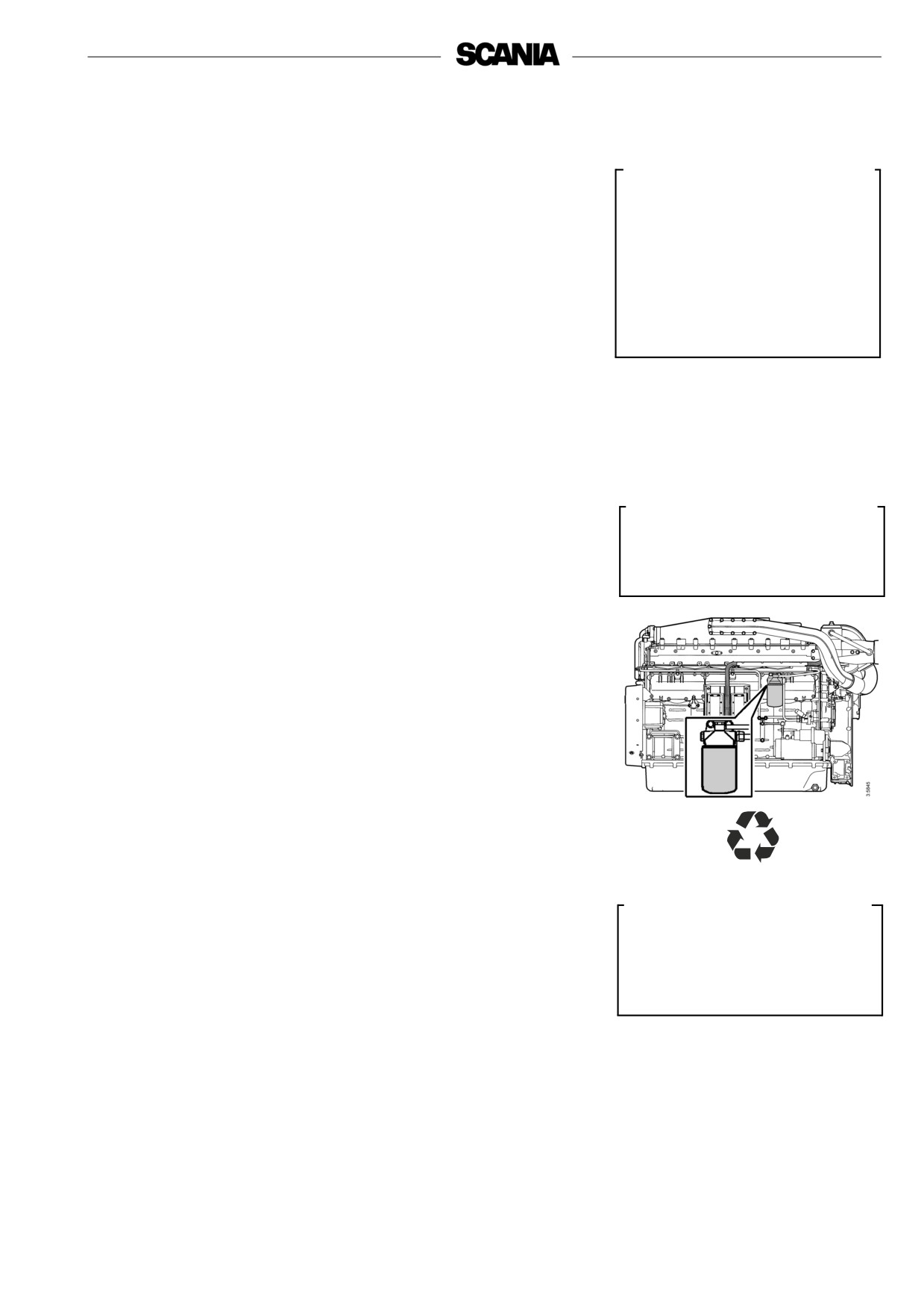
9. Every 4,800 hours:
Cleaning the cooling system
Note: If necessary, the cooling system should be cleaned more often.
Help protect our
environment!
External cleaning
Use a container to avoid spills
Heat exchanger
when changing the coolant.
1.
Start by removing the filler cap from the expansion tank and then drain
Dispose of used coolant through
the coolant from the engine using the tap on the right-hand side of the
an authorised waste disposal
engine block and by removing two plugs (2) from the underside of the
contractor.
heat exchanger.
2.
Drain the sea water circuit by removing the cover from the sea water
pump and the connections from the heat exchanger outlet.
!
3.
Detach the pipes to the charge air cooler and the charge air cooler
thermostat housing. Detach the pipe between the front cover and the
Important
heat exchanger.
The cooling system must never
4.
Remove the connection housing at the coolant pump inlet and the return
be cleaned with caustic soda.
pipe (16) to the pump.
There is a risk of damage to
5.
Remove the thermostat housing cover and the outlet pipe (17) to the heat
aluminium parts.
exchanger.
6.
Detach the flange at the sea water inlet to the heat exchanger.
7.
Remove the bleed pipe from the expansion tank.
8.
Remove the flange nuts (15) and lift off the heat exchanger assembly.
!
9.
Remove the cover (9) at the rear end and pull out the cooler core (6).
Important
10.
Clean the outside of the core. Use a paraffin-based engine cleaner.
Use silicone or teflon-based
11.
Remove any internal deposits mechanically using a round rod.
grease to lubricate the O-rings.
Only lubricate the O-rings, too
12.
Renew gaskets and O-rings. Lubricate and fit the O-ring (4) inside the
much grease can cause leakage
heat exchanger housing and assemble the heat exchanger.
Note: The O-ring (4) should be marked with 4 red dots.
13. Refit the heat exchanger assembly. Tighten the flange nuts to 50 Nm.
14. Refit the inlet and outlet pipes, the thermostat housing, the coupling
housing and the charge air cooler pipes.
15. Fill the system with coolant according to specification.
16. Start the engine and check that no leakage occurs. Check the level of the
coolant and top up as necessary.
36
Heat exchanger
1.
Heat exchanger housing
2.
Plug
18
19
3.
Gasket
1
16
4.
O-ring
5.
Gasket
6.
Cooler core
5
7.
Gasket
18
8.
O-ring
17
9.
Rear cover
10.
Screw
11.
Front cover
12
11
12.
O-ring
13.
Screw
15
14.
Sealing ring
3
15.
Flange nut
10
14
2
16.
Return pipe to coolant pump
9
4
17.
Outlet pipe from engine
7
13
18.
O-ring
19.
Pressure cap
6
8
37
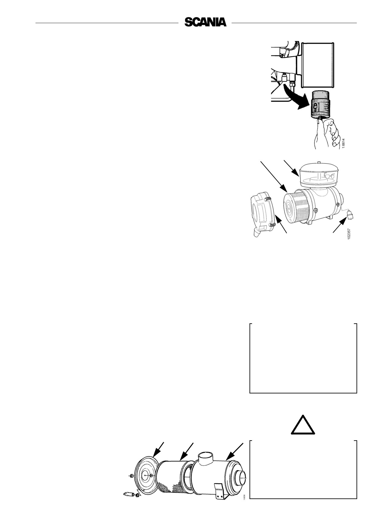
Engines with a sea water-cooled charge air cooler
should also be checked according to the
instructions below.
Sea water-cooled charge air cooler
1. Empty the sea water circuit and release the charge air cooler sea water
inlet and outlet connections.
2. Remove both covers from the charge air cooler and pull out the cooler
core.
3. Clean the outside of the core. Use a paraffin-based engine cleaner.
4. Remove any internal deposits mechanically using a round rod.
5. Renew all the O-rings and assemble the heat exchanger. Torque tighten
the screws on the cover to 26 Nm.
6. Reattach the charge air cooler sea water inlet and outlet connections.
1. Cover
2. Cover
3. Screw
4. O-ring
5. Charge air cooler core
6. Flange
7. Sacrificial anode
38

Charge air cooler
1.
Drain the coolant from the engine.
2.
Undo and remove the air pipe from the upper part of the intake
manifold.
3.
Detach the charge air cooler inlet and outlet connections for the coolant.
Remove the cover with thermostat housing and the intake manifold from
Help protect our
the core connection.
environment!
4.
Remove the screws between the upper and lower parts of the intake
Use a container to avoid spills
manifold and lift off the upper part of the intake manifold. Take care not
to damage the core’s water connections.
when changing the coolant.
Dispose of used coolant through
5.
Plug the holes in the core and unscrew the core fastening bolts. Lift out
the charge air cooler core.
an authorised waste disposal
contractor.
6.
Clean the outside of the core. Use a paraffin-based engine cleaner.
7.
Clean the sealing surfaces of the upper and lower parts of the intake
manifold and fit the core to the lower part of the intake manifold. Torque
tighten the screws to 26 Nm.
8.
Fit a new gasket on the lower part of the charge air cooler and screw on
the upper part. Tighten the screws to 26 Nm.
9.
Lubricate and fit new O-rings in the connecting pipe (8) for the coolant
inlet and push it onto the core inlet pipe. Fit a new V-seal (6) on the
pipe.
10.
Lubricate and fit new O-rings in the connection pipe on the cover with
thermostat housing (7). Fit the cover on the inlet and outlet on the core,
and screw it onto the upper part of the manifold (4) with a new gasket
(5). Tighten the screws to 26 Nm.
11.
Refit the turbocharger air pipe to the upper part of the intake manifold.
Tighten the screws to 26 Nm.
12.
Refit the inlet and outlet pipe connections to the charge air cooler.
13.
Top up with coolant according to specification.
4
3
5
8
7
1. Intake manifold, lower part
2. Gasket
3. Charge air cooler core
4. Intake manifold, upper part
2
5. Gasket
6. V-ring seal
7. Cover with thermostat housing and
6
thermostat
8. Connection pipe
9
9. O-ring
1
39
Internal cleaning
Removing oil and grease
- If possible, run the engine until it has reached operating temperature and
Help protect our
then drain the cooling system.
environment!
- Remove the thermostats.
- Fill the system with clean, hot water mixed with liquid dishwasher
Use a container to avoid spills
detergent designed for household use. Concentration 1% (0.1/10 l).
when changing the coolant.
- Run the engine until warm for about 20-30 minutes. Do not forget the
Dispose of used coolant through
cab heating system (if fitted).
an authorised waste disposal
contractor.
- Drain the cooling system.
- Fill the system again using clean, hot water and run the engine for about
20-30 minutes.
- Drain the water from the system.
!
- Refit the thermostats.
WARNING
- Top up the system with new coolant according to the specification.
When handling cooling system
detergent:
Removing deposits
read the warning text on the
- If possible, run the engine until it has reached operating temperature and
containers.
then drain the cooling system.
- Remove the thermostats.
- Fill the system with clean, hot water mixed with a commercially
available radiator cleaning agent which is based on sulphamic acid and
contains dispersing agents. Follow the manufacturer’s instructions for
the concentration and cleaning period.
- Run the engine for the specified time and then drain the cooling system.
- Refill the system with hot water and run the engine for about
20-30 minutes.
- Drain the water from the system.
- Refit the thermostats.
- Fill the system with new coolant according to specification.
40
Air cleaner
10. Daily:
Checking the read-out from the vacuum
indicator
If the red indicator bar is entirely visible, renew or clean the air cleaner filter
element, point 12. This is particularly important if the engine is run at high
loads and high speed.
11. Every 200 hours:
1
2
Cleaning the air cleaner’s coarse
cleaner
1. Remove the cover from the coarse cleaner (2).
2. Remove the conical coarse separator. Empty out the particles of dirt and
clean it.
3. Fit the coarse cleaner as shown in the figure and screw the cover into
place.
3
4
1. Filter element
12. Every 1,200 hours:
2. Coarse cleaner
3. Cover
Cleaning or renewing the filter element
4. Vacuum indicator
Note: Earlier if vacuum indicator shows red.
Air cleaner with coarse cleaner
Dismantling
1. Remove the side cover from the air cleaner.
!
2. Renew or clean the element.
Important
Note: Cleaning the element always entails a risk of damaging it. The
Only use genuine Scania air
element can only be cleaned a maximum of four times. After
filters.
cleaning, it has poorer dust capacity than a new element.
Renew the filter element if it is
3. Mark the filter when it has been cleaned.
damaged.
Cleaning the element
Danger of engine damage if the
filter element is damaged.
- Carefully blow the filter element clean using dry compressed air from
the inside.
Note: This filter element must not be washed with water.
!
1
2
3
WARNING
Never start the engine without
the air filter.
1. Cover
There is a risk of injury or
2. Filter element
serious engine damage.
3. Filter housing
41

Check
- Insert a torch into the element and check from the outside that there are
no holes or cracks in the filter paper.
- Renew the filter element if it has the slightest damage. Danger of engine
damage.
Assembly
1. Assemble the air cleaner in reverse order.
2. Reset the vacuum indicator by pressing the button.
Filter with a non-renewable element (unit cleaner)
Cleaning
- The filter may be cleaned a maximum of 3 times. Mark the filter after
each time it has been cleaned.
- Use a cleaning solution consisting of water mixed with approx. 1% mild
detergent.
1. Pour the cleaning solution into the element outlet at the same time as
turning the element so that the cleaning solution pours through the
element against the direction of the air flow.
2. Leave the element in the cleaning solution for 5 minutes and then take it
out so that all the cleaning solution drains away.
3. Rinse the filter with about 30 litres of clean water at 30-40°C. Pour the
rinsing water through the element in the same way as you did the
cleaning solution.
4. Take out the element and allow the rinsing water to drain off.
5. Repeat this procedure until the rinsing water is clean.
6. Leave the element to dry in a warm place for approximately 24 hours.
Note: The filter must not be dried with compressed air.
13. Every 2,400 hours:
Renewing the safety cartridge
1
Note: Not all filters are equipped with a safety cartridge. When
changing the safety cartridge, take great care to ensure that no
dirt or other impurities can get into the engine.
1. Remove the side cover from the air cleaner.
2. Remove the filter element.
3. Remove the safety cartridge.
1. Safety cartridge
4. Fit a new genuine Scania safety cartridge.
5. Renew or clean the filter element, see point 12.
6. Assemble the air cleaner.
!
Important
Never clean the safety cartridge.
42
Fuel system
!
14. Daily:
Important
Checking the fuel level
Observe the utmost cleanliness
when working on the fuel
- Top up with fuel if necessary. At the same time, drain the water
system.
separating filter.
There is a risk of engine
- If the tank has been run dry, bleed the fuel system, see point 15.
malfunction and damage to the
injection equipment.
15. Every 1,200 hours:
!
Renewing the fuel filter
Important
Fuel tanks
Use only genuine Scania fuel
filters.
- Drain any water from the fuel tanks.
Main filter
The filter consists of a filter unit.
- Wash the outside of the filter and unscrew it.
- Fit the new filter and tighten it by hand.
Never use tools for this. The filters can be damaged, obstructing
circulation.
- Bleed the fuel system according to the instructions overleaf.
- Start the engine and check for leaks.
Help protect our
environment!
Use a container to avoid spillage
when bleeding and renewing
components.
43
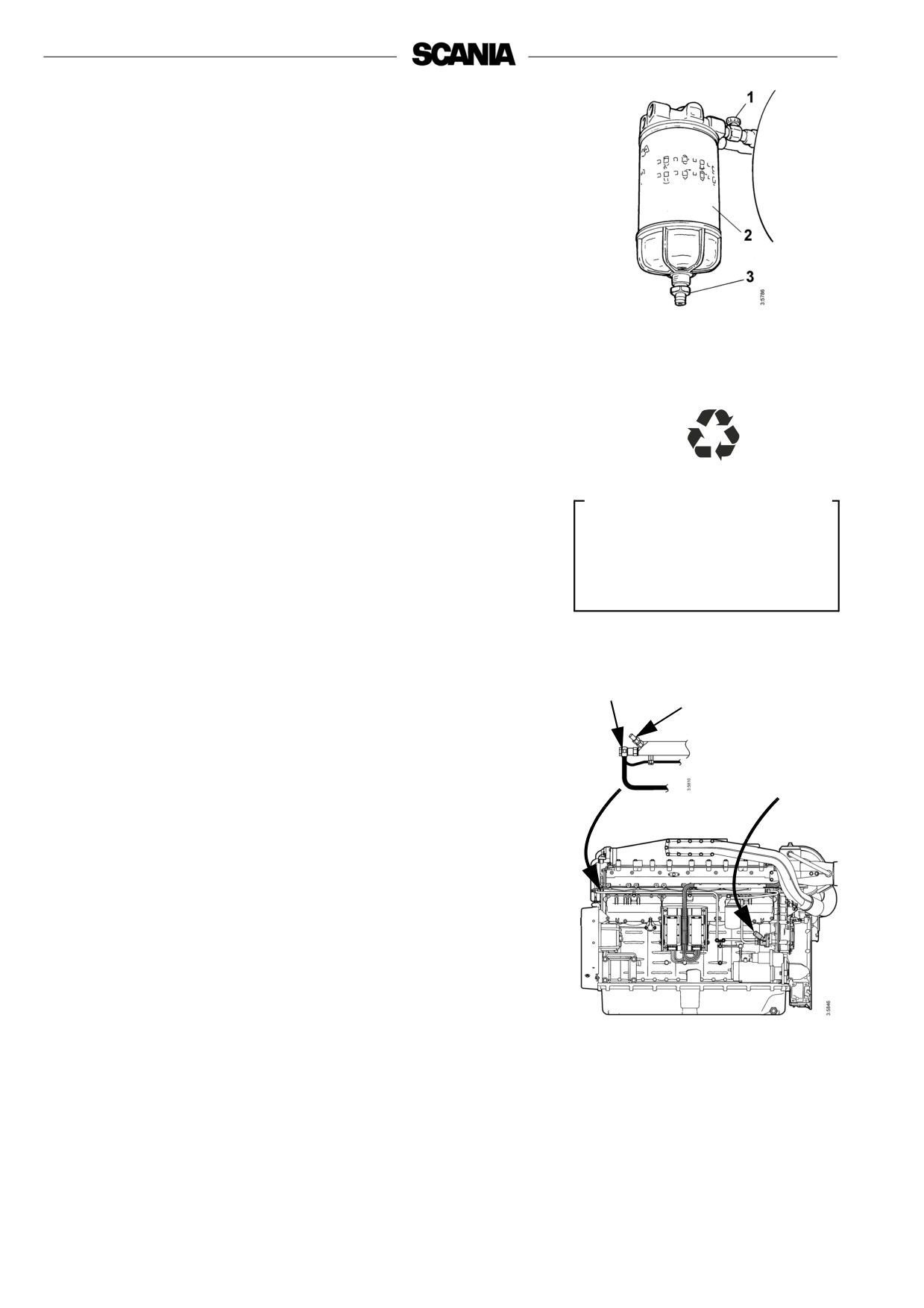
Water separating filter
- Drainage must be carried out when filling fuel.
- The filter must be renewed at the same renewal interval as the main
filter.
- Close the cock (1) upstream of the filter.
- Unscrew the container and drain valve (3).
- Unscrew and renew the filter (2). Lubricate the seal before tightening
the new filter by hand.
1. Shut-off cock
- Screw the container and drain valve into position.
2. Filter
- Open the cock (1).
3. Drain valve
- Bleed the fuel system after renewing both filters.
Help protect our
environment!
Use a container to avoid spillage
when bleeding and renewing
components.
Bleeding the fuel system
- Attach a clear plastic hose to the bleed nipple (1) to channel fuel into a
container. The bleed nipple is located at the end of the fuel manifold at
the front of the engine.
- Open the bleed nipple.
3
- Pump with the hand pump (2) until the fuel flowing out of the opened
1
bleed nipple is free of air bubbles.
• If the system is completely empty, it will take approximately
250 strokes.
2
• After renewing the fuel filter, it will take approximately 170 strokes.
• Approximately 150 strokes are required to bleed the fuel manifold.
- Close the bleed nipple and remove the hose.
- Undo the banjo screw for the overflow valve (3) slightly. Pump the hand
pump an additional 20 strokes until the overflow valve opens.
- Start the engine and check for leaks.
Important! The starter motor may only be used for 30 seconds at a time.
After that time it must rest for 2 minutes.
If the engine fails to start after bleeding:
- Open the bleed nipples again and pump the hand pump until fuel
without air bubbles flows out.
- Tighten the bleed nipples. Start the engine and check for leaks.
44
Electrical system
!
16. Every 200 hours:
WARNING
Checking the electrolyte level in
Avoid naked flames or sparks
batteries
near the batteries.
1. Unscrew the plugs and check the electrolyte level in all cells.
When the batteries are charged,
oxyhydrogen gas is formed
2. Top up with distilled water until the level is 10-15 mm above the plates.
which is flammable and
explosive.
17. Every 1,200 hours:
Checking the state of charge in
batteries
!
WARNING
- Check the density with an acid tester.
In a fully-charged battery it should be:
Wear gloves and protective
1.280 at +20ºC
goggles when charging and
handling batteries.
1.294 at 0º
The batteries contain a highly
1.308 at -20ºC
corrosive acid.
- If the density is below 1.20, the battery must be charged. A discharged
battery freezes at -5°C.
Do not boost charge the battery. This will damage the battery in the long
run.
!
WARNING
18. Every 1,200 hours:
Do not connect the terminals
Cleaning batteries
incorrectly.
This can cause serious damage
1. Clean batteries, cables and cable terminals.
to the electrical system.
2. Check that all cable terminals are firmly tightened.
If the terminals are shorted,
3. Grease the battery terminals and cable terminals with Vaseline.
sparking will occur.
45

Renewing the battery
!
Removal
WARNING
1. Disconnect the negative cable (-) from the battery (cable connected to
earth).
Do not connect the terminals
2. Disconnect the positive cable (+) from the battery (cable connected to
incorrectly.
starter motor).
This can cause serious damage
Fitting
to the electrical system.
If the terminals are shorted,
1. Connect the positive cable (+) to the battery (cable connected to starter
sparking will occur.
motor).
2. Connect the negative cable (-) to the battery (cable connected to earth).
Help protect our
environment!
Dispose of used batteries
through an authorised waste
disposal contractor.
19. Every 1,200 hours:
Checking the coolant level monitor
(Optional equipment)
1. Start the engine.
2. Reduce the coolant level in the expansion tank to below the level
monitor.
3. Automatic stop in the event of a fault: The engine stops, the indicator
lamp comes on and the buzzer (if fitted) sounds if there is no fault in the
level monitor. If the function is connected via the coordinator, the
emergency stop fault code will be generated and can be read off on the
diagnostics lamp.
4. No automatic stop in the event of a fault: The indicator lamp comes on
and the buzzer (if fitted) sounds if there is no fault in the level monitor.
5. Top up coolant to the correct level.
Help protect our
environment!
Use a container to avoid spills
when draining the coolant.
Dispose of used coolant through
an authorised waste disposal
contractor.
46
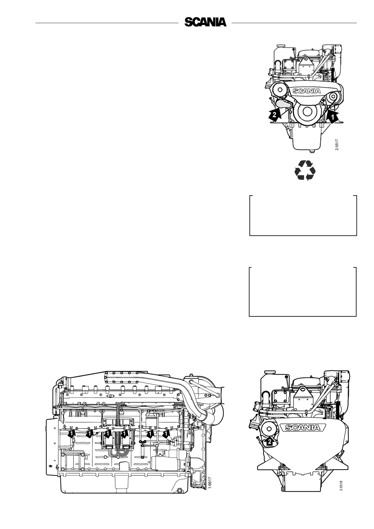
Miscellaneous
20. Every 1,200 hours:
Checking the drive belt
- If the drive belt (1), which is a poly-V belt, is worn or damaged it must
be renewed.
- Also check that the automatic belt tensioner (2) is in proper working
order and keeps the drive belt correctly tensioned.
21. Daily:
Check for leaks, rectify as necessary
Help protect our
environment!
- Start the engine.
Take care to ensure that any
- Check for oil, coolant, fuel, air and exhaust leaks.
leaks do not cause pollution.
- Tighten or renew leaking connections. Check the overflow holes (1)
(below the side covers) which show whether the O-rings between the
cylinder liners and crankcase are leaking, see figure.
a) If coolant is running out, the O-ring is leaking.
!
b) If lubricating oil is running out, the liner shelf is leaking.
Important
- Check that the coolant pump drain hole (2) is not clogged, see figure. If
there is a leak, renew the pump seal or the complete coolant pump.
If serious leakage occurs,
contact your nearest Scania
- A small amount of leakage from the overflow holes during the engine
workshop.
running-in period is normal. (Sealing rings and O-rings are lubricated
with soap or oil when fitted).
- This leakage normally stops after a time.
47