Scania DI12 EMS with S6/PDE. Marine engine. Operator’s manual - part 2
Troubleshooting using flash codes for the EMS
coordinator
• The diagnostics lamp on the instrument panel(s) always comes on for
two seconds when the system is powered up.
• As soon as a fault is detected by the coordinator, it is stored in the
EEPROM fault code memory and the diagnostics lamp on the
instrument panel(s) comes on.
• Even if the lamp has gone off and the fault is no longer active, the code
can generally be read off by following the instructions below.
Reading off coordinator fault codes
1. Turn on the ignition.
2. Activate the diagnostics switch to the right for 1 second to view the flash
codes for the coordinator (COO).
3. A fault code will then flash on the diagnostics lamp. This flash code
consists of long flashes (approximately 1 second long) and short flashes
(0.3 seconds long). Long flashes are equivalent to tens and short flashes
to ones.
Example: long - short - short = fault code 12.
4. Repeat this procedure until the first flash code is repeated. This means
that the entire fault code memory has been flashed out. If the fault code
memory is empty, only one long flash (approx. 4 seconds long) will be
given.
5. See the flash code table on the next page for a description and to locate
the fault.
6. In order to obtain further information about the fault code, the PC-based
diagnostics tool or Scania EMS Display must be used. Contact an
authorised Scania workshop.
7. When a fault has been rectified the fault code can be erased as described
below.
Clearing fault codes
1. Switch off the ignition. If dual instrumentation has been fitted, the
ignition must be switched off on both panels.
2. Activate the diagnostics switch in the same direction as the flash codes
indicate, i.e. to the right for the coordinator (COO) or to the left for
EMS.
3. Switch on the ignition and at the same time keep the diagnostics switch
activated, to the right (COO) or to the left (EMS), for 3 seconds.
4. This will erase passive fault codes which can be read via flash codes for
the relevant system. The rest of the fault codes will remain in the
EEPROM and can only be deleted using the PC tool.
16

Overview of flash codes for the EMS coordinator
Flash code
Fault description
111)
Incorrect signal from the fine adjustment for the nominal engine speed signal.
112)
Incorrect signals from the accelerator pedal sensor.
121)
Incorrect signal from the resistor module for governor setting.
122)
Incorrect signal from the resistor module for idle and fixed speed setting.
13
No communication (EMS) with the engine.
14
Short circuit in the tachometer signal cable.
15
Faulty atmospheric pressure sensor.
17
Short-circuit in the coolant temperature gauge signal cable.
18
Short circuit in the oil pressure gauge signal cable.
19
Short circuit in the oil pressure lamp signal cable.
21
Different versions of the communications protocol in the coordinator and EMS.
22
Faulty start switch or short circuit.
23
The supply voltage is too high.
24
The supply voltage is too low.
25
Check value from End of line (EOL) is incorrect.
26
Road speed sensor signal missing or incorrect.
27
The signals from the RCB (Remote Control Box) switches are implausible.
28
Incorrect signals from the droop setting switches.
29
Faulty remote start switch or short circuit.
31
No communication from the slave coordinator or the master coordinator.
32
Short circuit in the signal cable to the coolant temperature warning lamp.
33
Short circuit in the signal cable to the charge warning lamp.
34
Incorrect signal from the Fixed speed switches.
35
Fault in CAN communication.
1) Single speed engine
2) All-speed engine
17
Starting and running
First start
Coolant composition:
When the engine is started for the first time, the maintenance points listed
If there is a danger of freezing:
under "First start" in the maintenance schedule should be followed.
minimum 30% glycol by
Since the points are important for satisfactory operation of the engine right
volume
from the outset, they are also listed below.
maximum 60% glycol by volume
1. Checking the oil level; see page 27.
If there is no danger of freezing:
8. Checking the coolant; see page 33.
8-12% by volumeScania
Corrosion Inhibitor.
The coolant must contain corrosion inhibitor to protect the cooling
system from corrosion.
If there is a danger of freezing:
!
- Only antifreeze glycol should be used in the coolant as protection
WARNING
against corrosion. We recommend only nitrite-free antifreeze glycols
with the following supplier designations:
Ethylene glycol and corrosion
BASF G48 or BASF D542
inhibitor are highly dangerous
- The concentration of glycol should be 30-60% by volume depending on
if imbibed. Avoid contact with
the ambient temperature. 30% glycol by volume provides antifreeze
the skin.
protection down to -16°C, see cooling system.
- Never top up with water alone or glycol alone! Fluid losses must always
be replaced with pre-mixed coolant having the same glycol
concentration as that in the engine. If the glycol content drops, both
!
antifreeze protection and protection against corrosion are impaired.
Important
Note: A glycol concentration below 30% by volume will not provide
The recommended glycols must
sufficient protection against corrosion. Glycol concentrations
not be mixed with glycol
higher than 60% do not improve antifreeze protection and have
an adverse effect on engine cooling capacity.
containing nitrite-based
corrosion inhibitor.
If there is no danger of freezing:
- Only Scania Corrosion Inhibitor should be used in the coolant as
protection against corrosion. The correct concentration of corrosion
inhibitor is 8-12% by volume, and this must never drop below 8% by
!
volume. The inhibitor in Scania Corrosion Inhibitor is free of nitrites.
Important
- First filling: Fill up the system with water + 10% by volume Scania
Corrosion Inhibitor. Use drinking water with a pH of 6-9.
Overdosing with Scania
Corrosion Inhibitor and mixing
- Never top up with water alone or corrosion inhibitor alone! Fluid losses
must always be replaced with blended coolant:
with glycol can cause sludge to
water + 10% Scania Corrosion Inhibitor by volume.
be formed.
Coolant filter (not standard equipment)
Only coolant filters without inhibitor may be used. The use of coolant filters
!
increases the life of the coolant and reduces the risk of deposition corrosion.
Important
If a coolant filter has been fitted
it must not contain inhibitor.
18
14. Checking the fuel level; see page 43.
16. Checking the electrolyte level in batteries; see page 45.
17. Checking the state of charge in batteries; see page 45.
!
20. Checking the drive belt tension; see page 47.
WARNING
Block the starting device when
working on the engine. If the
engine starts unexpectedly,
there is a SERIOUS RISK OF
INJURY.
Checks before running
Before running, "Daily maintenance" as described in the maintenance
schedule should be carried out; see page 25.
!
WARNING
Starting the engine
Only start the engine in a well
If the fuel tank has been run dry or if the engine has not been used for a long
ventilated area.
time, bleed the fuel system.
If it is run in a enclosed space,
Out of consideration for our common environment, your Scania engine has
there should be an effective
been designed to use less fuel when starting. Using unnecessarily large
amounts of fuel when starting the engine always results in emissions of
device to draw off exhaust gases
unburnt fuel.
and crankcase gases.
- Open the inlet valve for the sea water system (if fitted).
- Open the fuel cock if fitted.
- Disengage the engine.
!
- Engines with battery master switch: switch on the power using the
battery master switch.
WARNING
- Start the engine with the key in the control panel (SCP) or the start
Never use starter spray or
button (only from RCB).
similar agents to help start the
- S6: The diagnostics lamp should go out after approximately 2 seconds
engine.
when starting.
An explosion may occur in the
intake manifold with a risk of
personal injury.
19
Starting at low temperatures
Local environmental requirements must be complied with. Starting aids,
engine heaters should be used to avoid starting problems and white smoke.
!
To limit white smoke, the engine should be run at low speed and under
moderate load. A moderate load on a cold engine gives better combustion and
Important
faster heating than warming up with no load.
The starter motor may only be
Avoid running it longer than necessary at idling speed.
cranked for a maximum of
At temperatures below 0°C:
30 seconds. There is a risk of
overheating. Let the starter
Note: Only use starting aids recommended by Scania.
motor rest for 30 seconds
- The starter motor must only be cranked for 30 seconds at a time. After
between each attempt to start
that it must rest for 30 seconds before the next attempt to start it. Only 5
attempts may be made to start the engine. After that the starter motor
must rest for 15 minutes before the procedure can be repeated.
Note: If the engine is equipped with an INTERLOCK switch, this
switch should be depressed and held down until the oil pressure
has reached a sufficiently high level.
Running
Check instruments and warning lamps at regular intervals.
Engine speed
The Scania tachometer is divided into different coloured sectors, as follows:
0-500 rpm
red area:
prohibited engine speed, passed
through when stopping and
starting.
500-700 rpm
yellow area:
slow idle. Engine idling is
controlled by the EMS/S6
control system. Fixed raised
idling speed with a cold engine.
700-2,200 rpm
green area:
normal operating speed
The engine operating speed
range is controlled by the
EMS/S6 control system.
2,200-2,600 rpm
yellow/green
unsuitable operating speed.
striped:
May occur when switching off.
2,600-3,000 rpm
red area:
prohibited engine speed.
20
Limp home mode
If there is a fault on the normal accelerator pedal or if CAN communication is
interrupted, the following limp-home option is available:
CAN outage or accelerator pedal malfunction (both signal and idling switch):
- The accelerator pedal value is 0% and the engine is running at normal
idling speed.
- The accelerator pedal value is 0% and the engine is running at raised
idling speed (750 rpm) if this function is activated.
Accelerator pedal malfunction but the idling switch is working:
- The accelerator pedal value can be increased slowly between 0-50% by
using the idling switch.
CAN outage:
- The engine is switched off if the shutdown function is activated.
Coolant temperature
Normal coolant temperature when the engine is running should be 70-90ºC.
The EMS/S6 control system has the following alarm levels:
- If the temperature is high, 98°C-103°C, for a certain period (1 second),
S6 will send a CAN message which switches on the warning lamp and
diagnostics lamp via the coordinator.
- If the temperature exceeds 103°C, the warning lamp and diagnostics
lamp will come on. If torque reduction is activated, the control system
will reduce the fuel quantity to 70%. A fault code is generated in the
control unit.
- At temperatures exceeding 103°C and with engine shutdown activated,
the warning lamp and diagnostics lamp come on and the engine is
switched off. If the override function is activated, only torque reduction
takes place when this function is activated. A fault code is generated in
the control unit.
After an alarm, approved values should be registered for more than 2 seconds
to reset the alarm.
Excessively high coolant temperature can damage the engine.
If run for extended periods under an extremely light load, the engine may
have difficulty in maintaining normal operating temperature. However, the
temperature will rise to a normal level again when the load on the engine is
increased.
21
Oil pressure
Max. oil pressure:
warm engine running at a speed above 800 rpm 6 bar
Normal oil pressure:
warm engine at operating speed 3-6 bar
High lubricating oil pressure
Min. oil pressure:
(above 6 bar) is normal when
warm engine running at a speed of 1,000 rpm 2.3 bar
starting a cold engine.
The control system has the following alarm levels:
- at a speed of less than 1,000 rpm and an oil pressure of less than 1.0 bar
- at a speed of more than 1,000 rpm and an oil pressure of less than
2.3 bar for longer than 5 seconds.
The following functions are available if there is an alarm:
- Alarm which only switches on the warning lamp and diagnostics lamp.
- Alarm which switches on the warning lamp and diagnostics lamp as
well as torque reduction if this function is activated (70% of fuel
quantity). A fault code is generated in the control unit.
- Alarm which switches on the warning lamp and diagnostics lamp. The
engine is switched off if engine shutdown is activated. If the override
function is activated, only torque reduction takes place when this
function is activated. A fault code is generated in the control unit.
After an alarm, approved values should be registered for more than 1 second
to reset the alarm.
22
Charging indicator lamp
If the lamp comes on during operation:
- Check and adjust the alternator drive belt as described under the
maintenance point. See Miscellaneous.
- If the charging indicator lamp is still on, this could be due to an
alternator fault or a fault in the electrical system.
!
Stopping the engine
Important
1. Run the engine without a load for a few minutes if it has been run
continuously with a heavy load.
There is danger of turbocharger
damage and post boiling if the
2. Stop the engine with the stop button or the starter key (depending on the
engine is stopped without
model). Keep the stop button depressed until the engine has stopped
completely.
cooling.
3. Before disconnecting the power, check that the control system
diagnostics lamp is not on. See page 16 for troubleshooting.
!
4. Set the control switch to the "0" position.
Important
5. Engines with battery master switch: switch the power off with the
battery master switch.
The power must not be switched
off before the engine has
stopped.
Note: If the engine is stopped improperly 10 times, torque reduction
will be activated (70% fuel volume). To reset the engine, switch
off the engine once in the prescribed manner.
!
WARNING
Checks after running
Block the starting device when
- Check that the power is cut from the battery master switch and that the
working on the engine. If the
control switch is in the "0" position.
engine starts unexpectedly,
- Fill the fuel tank. Make sure that the filler cap and the area round the
there is a SERIOUS RISK OF
filler opening are clean to avoid contamination of the fuel.
INJURY.
- If there is a risk of freezing, the cooling system must contain enough
glycol. See page 18.
- Switch off inlet valve for the sea water system (if fitted).
- If there is danger of freezing the sea water system must be emptied.
!
- At temperatures below 0°C: prepare for the next start by connecting the
Important
engine heater.
Coolant should be topped up
when the engine is stopped after
the first start.
23
Maintenance
The maintenance programme covers 21 points, divided into the following
main groups:
Lubricating oil system
page 26
!
Cooling system
page 31
Air cleaner
page 41
WARNING
Fuel system
page 43
Block the starting device when
Electrical system, batteries, etc
page 45
Miscellaneous
page 47
working on the engine. If the
engine starts unexpectedly,
there is a SERIOUS RISK OF
The maintenance points are divided into intervals as follows:
INJURY.
Daily maintenance
Maintenance before the first start
Maintenance after the first 400 hours of operation
Periodic maintenance every 200 hours of operation (carried out at 200, 400,
600, 800, etc. hours)
Periodic maintenance every 400 hours of operation (carried out after 400,
800, 1,200, 1,600, etc. hours)
Periodic maintenance every 1,200 hours of operation (carried out at 1,200,
2,400, 3,600, etc. hours)
Periodic maintenance every 2,400 hours of operation (carried out at 2,400,
4,800 etc. hours)
Periodic maintenance every 4,800 hours of operation (carried out at 4,800,
9,600 etc. hours)
Annual maintenance
Maintenance every 5 years
Engines with few hours of operation
Emergency generator sets etc., that are not used regularly should be test run
and checked in accordance with the generator set manufacturer’s instructions.
!
Run the engine until it reaches operating temperature and then carry out the
maintenance points below:
Important
1. Checking the oil level.
For engines with few operating
5. Checking the coolant level.
hours that do not receive
10. Checking the vacuum indicator.
periodic maintenance according
to the maintenance schedule on
14. Checking the fuel level.
page 25, maintenance should be
16. Checking the electrolyte level in batteries.
carried out in accordance with
17. Checking the state of charge in batteries.
the schedule:
18. Cleaning the batteries.
"Every year"
"Every 5 years"
21. Check for leaks, rectify as necessary.
24
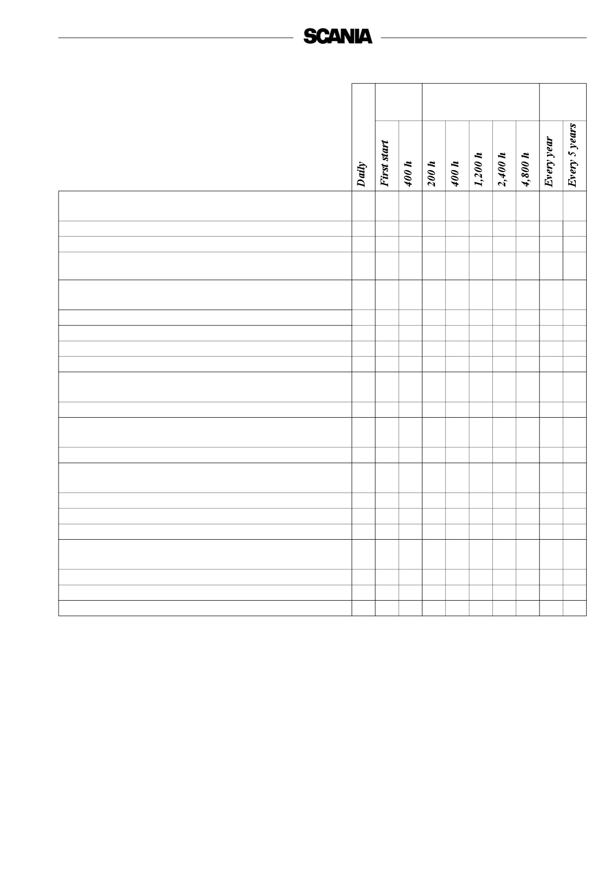
Maintenance schedule
First
Interval
At least
time at
Lubricating oil system, page 26
z
z
1. Checking the oil level
2. Oil change
z
1
z
3. Cleaning the lubricating oil cleaner
z
1
z
4. Renewing the oil filter and closed crankcase ventilation
z
1
z
filter
Cooling system, page 31
z
5. Checking the coolant level
6. Checking sacrificial anodes 4)
z
5
z
7. Checking the sea water pump impeller 4)
z
5
z
8. Checking the coolant
z
6
z6
9. Cleaning the cooling system
z
1
z
Air cleaner, page 41
z
10. Checking the read-out from the vacuum indicator
12. Cleaning or renewing the filter element
z
3
z
Fuel system, page 43
z
z
14. Checking the fuel level
15. Renewing the main filter and water separating filter
z
1
z
Electrical system, page 45
z
2
z
z
16. Checking the electrolyte level in batteries
17. Checking the state of charge in batteries
z
2
z
z
18. Cleaning the batteries
z
2
z
19. Checking the coolant level monitor
z
Miscellaneous, page 47
z
z
20. Checking the drive belt
21. Check for leaks, rectify as necessary
z
22. Checking/adjusting valve clearances
z
23. Checking/adjusting unit injector rocker arms
z
1. More often if required.
2. For engines with few operating hours, see page 24.
3. Earlier if vacuum indicator shows red.
4. Only applies to M engines with sea water pump and heat exchanger.
5. Guideline value. Varies depending on the composition of the sea water.
6. If inhibitor has not been topped up for five years, the coolant should be changed.
25
Lubricating oil system
Oil grade
The engine oil must at least meet the requirements for one of the following oil
classifications:
-ACEA E3, E4 or E5
- The Total Base Number (TBN) should be at least 12-13 (ASTM 2896).
!
- Check with your oil supplier that the oil meets these requirements.
Important
- Specified oil change intervals apply provided that the sulphur content of
Additives must not be used.
the fuel does not exceed 0.3% by weight. If the sulphur content is
The oil should be suitable for all
greater than 0.3% but no more than 1.0%, the oil change interval must
be halved (200 h).
temperature variations until the
next oil change.
- Viscosities are shown in the figure below.
- For operation at extremely low outdoor temperatures: Consult your
nearest Scania representative on how to avoid starting difficulties.
Oil analysis
Some oil companies can offer analysis of the engine oil. Such analysis
measures the oil’s TBN (Total Base Number), TAN (Total Acid Number),
fuel dilution, water content, viscosity and the quantity of wear particles and
soot in the oil.
The result of a series of analyses is used as the basis for establishing a
suitable oil change interval.
If the conditions are changed, a new oil analysis programme must be carried
out to establish the new change interval.
-40
-30
-20
-10
0
10
20
30
40
°C
SAE 20W-30
SAE 30
SAE 40
SAE 50
SAE 5W-30
SAE 10W-30
SAE 15W-40
26

1. Daily:
Checking the oil level
Note: Before checking the oil level: leave the engine switched off for at
least 1 minute.
- The correct level is between the marks on the oil dipstick. Top up when
the oil level is at the lower mark on the dipstick.
- Refer to page 26 for correct oil grade.
Checking the oil level during operation
On some engines the oil level can be checked during operation.
- Remove the oil filler cap to release the pressure in the crankcase.
- Check the level on the dipstick. Correct oil level: 10 mm below the Max.
mark.
Max.
Min.
2. Every 400 hours:
Oil change
Note: If the engine is used for especially demanding operations,
particularly in a dusty environment or if the deposits in the
centrifugal cleaner are thicker than 20 mm: change the oil more
frequently.
- Unscrew the oil plug and drain the oil when the engine is hot.
- In certain engines the oil is pumped out by means of a bilge pump.
3
- Clean the magnet on the oil plug.
Max. 33 dm
- Refit the oil plug.
Min. 28 dm3
- Fill with oil.
- Check the level on the oil dipstick.
!
Help protect our
WARNING
environment!
The oil may be hot.
Use a container to avoid
Wear protective gloves and
spillage when changing the oil.
Max. 28 dm3
goggles.
Dispose of used oil through an
Min. 20 dm3
authorised waste disposal
contractor.
1 dm3 = 1 litre
27

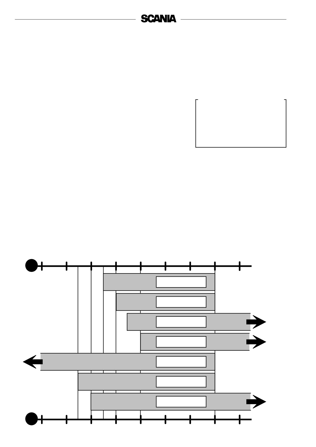
Maximum angles of inclination during operation
Maximum permissible angles during operation vary, depending on the type of
oil sump, see illustration.
Note: The specified angles may only occur intermittently.
25º
25º
25º
25º
35º
35º
35º
35º
3. Every 400 hours:
Cleaning the oil filter unit
(in connection with oil change)
- Clean the cover. Unscrew the nut and remove the cover.
!
WARNING
Open the cover carefully. The oil
may be hot.
- Lift out the rotor and wipe the outside. Unscrew the rotor cover nut
about one and a half turns.
- If the rotor nut is jammed: Turn the rotor upside down and fasten the
nut, but never the rotor, in a vice, and turn the rotor one and a half turns
anti-clockwise by hand, or use an M20 nut as illustrated.
- Hold the rotor and tap lightly on the rotor nut with a plastic mallet or
against the workbench, so that the rotor cover comes loose from the
bottom plate. Never strike on the rotor directly as this may damage the
bearings.
28
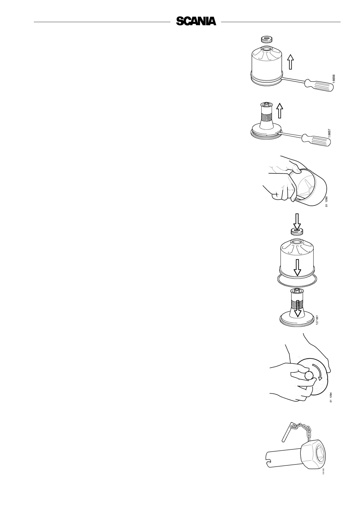
- Remove the nut and the rotor cover.
- Remove the strainer. If the strainer has seized in the rotor cover, prise
carefully using a screwdriver between the rotor cover and the strainer.
- If the strainer has seized in the rotor, prise carefully between the rotor
and the strainer.
- Scrape off the deposits from the inside of the rotor cover. If there are no
deposits, this indicates that the cleaner is not working properly.
- If the deposits are thicker than 28 mm: clean more often.
- Wash all parts in diesel.
- Make sure the nozzles on the rotor are not blocked or damaged.
- Check that the bearings are undamaged. If they are damaged the entire
rotor must be renewed.
- Fit a new O-ring on the rotor and fit the strainer.
- Reassemble the rotor.
- Tighten the rotor nut firmly by hand.
- Check that the shaft is not loose. If it is loose, use locking compound
561 200 and torque tighten to 34 Nm using tool 98 421.
- In order to tighten the rotor shaft, it is necessary to modify socket
wrench 98 421:
- Drill out the threads from a M20 nut so that it fits on the square drive
of the socket wrench.
- Weld the nut into place.
29

- Refit the rotor.
- Check that it rotates easily by rotating it manually.
- Fit a new O ring on the cover and fit the cover.
- Screw on the cover and tighten the lock nut to 15 Nm.
Tighten the nut carefully so as not to damage the rotor shaft, nut or cover.
Functional inspection
The rotor rotates very fast and should continue to rotate when the engine has
stopped.
- Stop the engine when it is warm.
- Listen for a whirring sound from the rotor or feel whether the cleaner
housing is vibrating.
The rotor normally continues spinning for 30-60 seconds after the engine has
stopped.
If not: dismantle and check.
4. Every 400 hours:
Renewing the oil filter
(At the same time as an oil change)
- Remove the old filter.
- Oil the rubber gasket and fit a new genuine Scania filter.
- Tighten the filter by hand. Never use tools for this. The filter could
sustain damage, obstructing circulation.
- Start the engine and check for leaks.
Important! If the deposits in the centrifugal cleaner are more than
20 mm thick, the oil filter must be renewed more often. The
same is true for cleaning the centrifugal filter and changing
the oil.
Help protect our
environment!
Use a container to avoid spillage
when renewing the filter.
Dispose of used filters through
an authorised waste disposal
contractor.
30
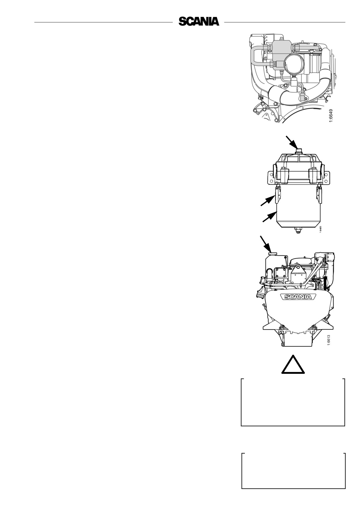
Renewing the closed crankcase
ventilation filter
In the case of engines with closed crankcase ventilation, the filter element
must be renewed at the same time as the main oil filter as described below:
- Remove the drainage line at the filter base.
- Release clamps (1) holding the container to the filter head.
- Remove the container (2). There may be oil in the bottom.
- Remove and renew the filter element.
- Renew the O-ring at the base of the head and check that there is an
O ring on top of the new filter element.
3
- Fit the new filter and press it into the centre of the filter head.
- Refit the container and lock firmly.
- If the indicator (3) on top of the filter showed red, remove the plastic
cover and press the indicator button.
- Refit the drainage line.
1
2
Cooling system
5. Daily:
Checking the coolant level
- Open the expansion tank filler cap and check the coolant level.
- Correct level:
- Cold engine: Coolant level must be approx. 50 mm below the full
line.
- Hot engine: Coolant level must be approx. 25 mm below the full
line.
!
- Other types of expansion tank according to the instructions of the fitter.
WARNING
- Top up the coolant as necessary, see point 8.
Open the cap carefully. Water
Note: When filling large amounts of coolant: Never pour cold coolant
and steam may spray out.
into a hot engine. This could crack the cylinder block and
cylinder head.
!
Important
Always top up with ready mixed
coolant.
31