Scania DI12 EMS with S6/PDE. Marine engine. Operator’s manual - part 1
IMPORTANT INFORMATION
When working on the engine, for example adjusting drive belts, changing the oil or adjusting the
clutch, it is important not to start the engine. The engine may be damaged and there is a
!
SERIOUS RISK OF INJURY
For this reason, always secure the starting device or disconnect a battery cable before working on
the engine. This is especially important if the engine has a remote starter or automatic starting.
This warning symbol and text is reproduced beside those maintenance points where the risk of
injury is particularly great.
Operator’s Manual
DI12
EMS with S6/PDE
Marine engine
opm_d12mar_ en-GB2 083 237
COMMISSIONING REPORT - WARRANTY
When the commissioning report has been filled in and sent to Scania, you have a 1-year warranty from the date
of commissioning.
Also fill in the details below; this can make things easier if you need to contact a service workshop for
example.
Engine serial number
Date of commissioning
Power class, see page 5
User’s name and address
Signature
Engine type
Variant
Engine type and variant are indicated on the engine type plate
Preface
This Operator’s Manual describes the handling and maintenance of Scania
DI12 Marine Engines with EMS S6/PDE injection systems.
The four-stroke, 6-cylinder in-line diesel engines have direct injection and are
liquid cooled. The engines are turbocharged and equipped with a charge air
cooler which is coolant-cooled, see page 12.
The engines can have two different cooling systems: a heat exchanger which
is cooled by sea water, or keel cooling which has cooling coils on the hull in
which the engine coolant is cooled.
Common areas of usage include propulsion engines in small boats like
fishing boats and ferries, and in larger pleasure crafts, or as auxiliary engines
on-board ships.
!
The engines can have different output and speed settings and are classified in
Important
different class categories (classed engines must be used in certain marine
installations).
See page 5 for information
The normal output setting of the engine (performance code) is indicated on
the type plate, see page 12.
about the power classification.
Note: Only standard components are described in the Operator’s
Manual. Please see the manufacturer’s instructions regarding
special equipment.
In order to obtain the best value and service life from your engine, there are
several points you should bear in mind:
- Read the manual before starting to use the engine. Even though you may
have experience of Scania engines you may find new information in this
Operator’s Manual.
!
- Follow the maintenance instructions. Good working order and service
Important
life are ensured if maintenance is carried out according to the
instructions.
During the warranty period,
only genuine Scania parts may
- In particular, read the safety information starting on page 6.
be used during service and
- Get to know your engine so that you know what it can do and how it
repair; otherwise the warranty
works.
will be invalidated.
- If necessary, contact an authorised Scania workshop. They have special
tools, genuine Scania parts and staff with training and practical
experience of Scania engines.
Note: Always use genuine Scania parts during service and repair so as
to keep your engine in the best possible working order.
The information in this manual was correct at the time of going to press.
However, we reserve the right to make alterations without prior notice.
2
Table of contents
Preface
2
Checking the coolant level
31
Contents
3
Checking the sacrificial anodes
32
Environmental responsibility
4
Checking the sea water pump impeller
32
Certified engines
4
Checking the coolant
33
Power classes
5
Checking the glycol content
33
Safety information
6
Checking the corrosion inhibitor
35
Safety precautions before running
7
Changing the coolant
35
Safety precautions for materials handling
8
Cleaning the cooling system
36
Safety precautions for care and maintenance . .8
Heat exchanger
36
Sea water-cooled charge air cooler
37
Type designations
10
Charge air cooler
38
EMS engine management system
12
Air cleaner
41
Troubleshooting using flash codes for the
Checking the read-out from the vacuum
EMS control unit
14
indicator
41
Overview of flash codes for the EMS
Cleaning the air cleaner’s coarse cleaner
41
control unit
15
Troubleshooting using flash codes
Cleaning or renewing the filter element
41
for the EMS coordinator
16
Renewing the safety cartridge
42
Overview of flash codes for the
EMS coordinator
17
Fuel system
43
Checking the fuel level
43
Starting and running
18
Renewing the fuel filter
43
First start
18
Bleeding the fuel system
44
Checks before running
19
Starting the engine
19
Electrical system
45
Starting at low temperatures
20
Checking the electrolyte level in batteries
45
Running
20
Checking the state of charge in batteries
45
Engine speed
20
Cleaning batteries
45
Limp home mode
21
Checking the coolant level monitor
46
Coolant temperature
21
Miscellaneous
47
Oil pressure
22
Checking the drive belt
47
Stopping the engine
23
Check for leaks, rectify as necessary
47
Checks after running
23
Checking and adjusting the valve
Maintenance
24
clearance
48
Engines with few hours of operation
24
Checking and adjusting the unit injector
rocker arms
50
Maintenance schedule
25
Preparing the engine for storage
54
Lubricating oil system
26
Preservative fuel
54
Oil grade
26
Preservative oil
55
Oil analysis
26
Preparation for storage
55
Checking the oil level
27
Batteries
56
Oil change
27
Storage
56
Maximum angles of inclination
Taking out of storage
56
during operation
28
Cleaning the oil filter unit
28
Technical data
57
Renewing the oil filter
30
Fuel
58
Renewing the closed crankcase
ventilation filter
31
Alphabetical index
61
Cooling system
31
Scania Assistance
62
3
Environmental responsibility
Scania has always been very much at the leading edge when it comes to
developing and producing engines which are as environmentally friendly as
possible.
Major progress has been made on reducing harmful exhaust emissions as
required to be able to meet the stringent environmental standards stipulated
on almost all markets.
At the same time, we have been able to maintain high quality in terms of
performance and operating economy for Scania Industrial and Marine
Engines.
To preserve these qualities throughout the entire service life of the engine, it
is important for the operator/owner to follow the instructions on running,
maintenance and the choice of fuel and lubricating oil as outlined in the
manual.
Other efforts to preserve the environment we all share are possible by
ensuring that the person carrying out servicing and maintenance always
makes sure that environmentally hazardous waste after servicing and repairs
(oil, fuel, coolant, filters, batteries, etc.) is dealt with and disposed of in
accordance with applicable environmental standards.
Help protect our
On a number of pages, this Operator’s Manual contains specially highlighted
environment!
text with instructions to help protect our environment during certain servicing
Use a container to avoid spillage
and maintenance work.
when bleeding and renewing
components.
See example
Certified engines
Emissions-certified engines have been approved in accordance with a special
certification standard. The certified engines supplied by Scania meet the most
stringent emissions standards which apply on European (EU) and non-
European (USA) markets.
Scania guarantees that all the engines it supplies of a certified type are
equivalent to the engine approved for certification.
The engine comes with a special certification plate which indicates the
certification rules (standard) to which the engine has been approved.
The following is required for the certified engine to meet emission standards
once it has been commissioned:
- Servicing and maintenance must be carried out in accordance with the
instructions in this manual.
- Only genuine Scania parts are to be used.
- Injection equipment is to be serviced by an authorised Scania workshop.
- The engine must not be modified with equipment not approved by
Scania.
- Seals may be broken and setting data edited only once approval has been
granted by Scania in Södertälje. Modifications may be made by
authorised personnel only.
- Modifications affecting the exhaust and intake systems must be
approved by Scania.
4
Otherwise, the instructions in the manual in respect of running, care and
maintenance of the engine shall apply. The safety precautions described over
the next four pages must also be observed.
Important! If servicing and maintenance are not carried out as
specified above, Scania can no longer guarantee that the
engine will comply with the certified design, nor can it take
responsibility for any damage that occurs.
Power classes
Scania supplies engines in 4 different power classes:
ICFN - Continuous operation: Unlimited number of operational hours per
year at a total load factor of 100%.
IFN - Periodic operation: Intended for periodic operation where full power
is available 1h/3h. The accumulated load factor must not exceed 80% of the
calculated load. Unlimited number of hours per year.
Patrol craft - long: Intended for periodic operation where full power is
available 1h/6h. In between periods of operation at full load, the engine speed
must be reduced by at least 10% of the maximum engine speed attained. The
maximum accumulated operating time must be 2,000 hours per year.
Patrol craft - short: Intended for periodic operation where the calculated
power is available 1h/12h. In between periods of operation at full load, the
engine speed must be reduced by at least 10% of the maximum engine speed
attained. The maximum accumulated operating time must be 1,200 hours per
year.
Below is a list of engine serial numbers and power classes for the engines that
are used in this installation:
Engine serial number:
Engine type:
Engine power:
Kw, at
rpm
Indicate below the type of operation, and enter it on page 1.
(
) ICFN - Continuous operation:
(
) IFN - Periodic operation:
(
) Patrol craft - long
(
) Patrol craft - short
5
Safety information
General
This Operator’s Manual contains safety information which is important so as
to avoid both personal injury and damage to the product/other property. See
!
also page 1.
Important
The text highlighted in text boxes on the right of a number of pages is
important for engine function and in order to avoid damage to the engine. If
Use only genuine Scania fuel
these instructions are not followed, your warranty may be invalidated.
filters.
See example.
Similar text may also appear in the text column, and in this instance it will be
marked Note: or Important.
!
WARNING
The warning text found in text boxes on the right of a number of pages which
is marked with a warning triangle and starts with WARNING is extremely
Block the starting device when
important and warns you of serious engine faults or incorrect handling which
working on the engine. If the
may lead to injury.
engine starts unexpectedly,
there is a SERIOUS RISK OF
See example
INJURY.
A list of the safety precautions to be followed when running and maintaining
Scania engines can be found on the next three pages. Similar text can often be
found at the relevant maintenance points, and here different levels of
importance are attached to such text in accordance with the above
description.
All points are marked !, so as to indicate how important it is to read through
each point in this section.
For safety reasons, smoking is not allowed:
• In the vicinity of the engine and in the engine room
• When refuelling and close to the filling station
• When working on the fuel system
• In the vicinity of flammable or explosive material (fuel, oils, batteries,
chemicals, etc.).
6
Safety precautions before running
Daily inspection
Starter lock
Always carry out a visual check of the engine and
If the control panel is not fitted with a key operated
engine room before starting the engine and once you
switch, there should be a lock on the engine room to
have stopped the engine after running.
prevent unauthorised starting of the engine.
This will enable you to easily detect fuel, oil or
Alternatively, a lockable on/off master switch or
coolant leaks, or any other abnormalities which may
battery master switch can be used.
require rectification.
Starter spray
Refuelling
Never use starter spray or similar agents to help start
There is a risk of fire and explosion when refuelling.
the engine. This can cause an explosion in the intake
The engine must be stopped and smoking is not
manifold and possible injury.
allowed.
Do not overfill the tank due to a risk of expansion,
Running
and close the filler cap properly.
The engine must not be run in environments where
Use only fuel recommended in the service
there is a risk of explosion as all of the electrical or
literature. Fuel of the wrong quality can cause the
mechanical components can generate sparks.
engine to malfunction or stop by preventing the
injection pump and injectors from operating as they
Approaching a running engine always poses a safety
should.
risk. Parts of the body, clothes or dropped tools can
get caught in rotating parts such as the fan and cause
This can cause damage to the engine and, possibly,
injury.
injury.
For personal safety all rotating parts and hot
surfaces must therefore be shielded as much as
Hazardous gases
possible.
Only start the engine in a well ventilated area. The
exhaust fumes contain carbon monoxide and
nitrogen oxides, which are toxic.
If it is run in a enclosed space, there should be an
effective device to extract exhaust gases and
crankcase gases.
7
Safety precautions for handling
Safety precautions for care and
materials
maintenance
Fuel and lubricating oil
Stop the engine
All fuels and lubricants and many chemicals are
Always stop the engine before maintenance and
flammable. Always follow the instructions on the
servicing unless stated otherwise.
relevant packaging.
Prevent unwanted starting by taking out the starter
All work on the fuel system must be done with the
key where applicable and disconnecting the power
engine cold. Fuel leaks and spillage on hot surfaces
using the master switch or battery master switch and
can cause fire.
locking them. Also put up a warning sign
somewhere appropriate, indicating that work is in
Store soaked rags and other flammable materials
progress on the engine.
safely so as to avoid spontaneous combustion.
Working with a running engine always poses a
safety risk. Parts of the body, clothes or dropped
Batteries
tools can get caught in rotating parts and cause
injury.
The batteries contain and emit oxyhydrogen gas,
particularly during charging, and this gas is
flammable and highly explosive. There must be no
Hot surfaces and fluids
smoking, naked flames or sparks near the batteries
or the battery compartment.
There is always a risk of sustaining burns when an
engine is hot. Therefore, take care not to come into
Incorrect connection of a battery cable or jump lead
contact with manifolds, the turbocharger, the sump,
can cause a spark, which in turn can cause the
hot coolant and oil in pipes and hoses.
battery to explode.
Lifting the engine
Chemicals
The engine lifting eyes must be used when lifting
Most chemicals such as glycol, corrosion inhibitors,
the engine. Check first that your lifting devices are
preservative oils, degreasing agents, etc. are
in good condition and of the correct size to lift the
hazardous to health. Always follow the safety
weight.
precautions on the relevant packaging.
Extra equipment on the engine can alter the centre of
Some chemicals, such as preservative oil, are also
gravity, which is why you may need additional
flammable.
lifting devices to balance the engine correctly and
Store chemicals and other materials which are
lift it safely.
hazardous to health in approved containers, marking
Never work underneath a suspended engine!
them clearly and storing them where they are
inaccessible to unauthorised persons. Always hand
in leftover or used chemicals to an authorised waste
disposal contractor.
Batteries
The batteries contain a highly corrosive electrolyte
(sulphuric acid). Take care to protect your eyes, skin
and clothes when charging or handling batteries.
Wear protective gloves and goggles.
If the acid splashes on your skin, wash it off with
soap and copious amounts of water. If acid splashes
in your eyes, flush them immediately with copious
amounts of water and contact a doctor.
Dispose of used batteries through an authorised
waste disposal contractor.
8
Electrical system
Cooling system
The engine must be stopped and the power
Never open the coolant filler cap if the engine is hot.
disconnected using the master switch or battery
Hot coolant or steam may spray out and cause burns.
master switch before working on the electrical
If you have to open or remove a cooling system
system.
component when the engine is hot, open the cap
External power supplies to extra equipment on the
very carefully and slowly to relieve the system
engine must also be disconnected.
pressure before removing the cap. Wear gloves as
the coolant is still very hot.
Dispose of used coolant through an authorised
Electric welding
waste disposal contractor.
When carrying out welding work close to and on the
engine, remove the battery leads and the cables to
the alternator. Also remove all connections to the
Fuel system
control unit, including the voltage supply.
Always wear gloves when looking for leaks or
Connect the weld clamp to the component to be
carrying out any other work on the fuel system. Also
welded and close to the welding point, never to the
wear protective goggles when testing injectors.
engine or in such a manner that the current can pass
Fuel escaping at high pressure can penetrate tissues
over to a mounting.
and cause serious injury.
When you have finished welding, connect the cables
Never use non-genuine parts in the fuel and
to the alternator and control unit before connecting
electrical systems as genuine parts are designed and
the batteries.
manufactured to minimise the risk of fire and
explosion.
Lubrication system
Hot oil can cause burns and skin irritation.
Before starting
Therefore, avoid skin contact with hot oil.
Fit all removed shields before starting the engine
Make sure that there is no pressure in the lubrication
again. Check that you have not left any tools or other
system before starting work on it. Never start or run
objects on the engine.
the engine with the oil filler cap removed, as this
Never start the engine without the air filter fitted.
may cause oil to be thrown out.
There is a risk of objects being sucked into the
Dispose of used oil through an authorised waste
compressor impeller or of injury if you come into
disposal contractor.
contact with it.
9
Type designations
Made by
The engine type designation indicates, in the form of a code, the engine type,
Type
D12 60M
Engine No
1023558
its size and applications.
Output.
kW
rpm.
Output
kW
rpm.
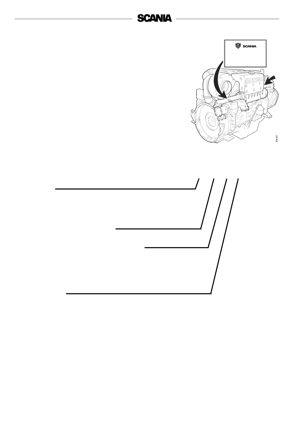
The type designation and engine serial number are specified on a type plate
affixed to the right-hand side of the flywheel housing. The engine serial
number is also stamped on the right-hand side of the cylinder block. See the
arrow in the illustration.
Engines which hold certification in respect of smoke and emissions are fitted
with a plate which indicates the documents in accordance with which they are
certified.
DI 12 60 M
Version
DI Supercharged diesel engine with liquid-cooled charge air cooler
Displacement in whole dm3
Performance and certification code
Indicates, together with the application code, the normal gross engine
output.
The actual output setting of the engine is indicated on the engine card.
Application
M For marine use
10
15
16
1
2, 3
4
5
14
13
6
12
7
11
9
8
10
24
17
18
23
22
19
21
20
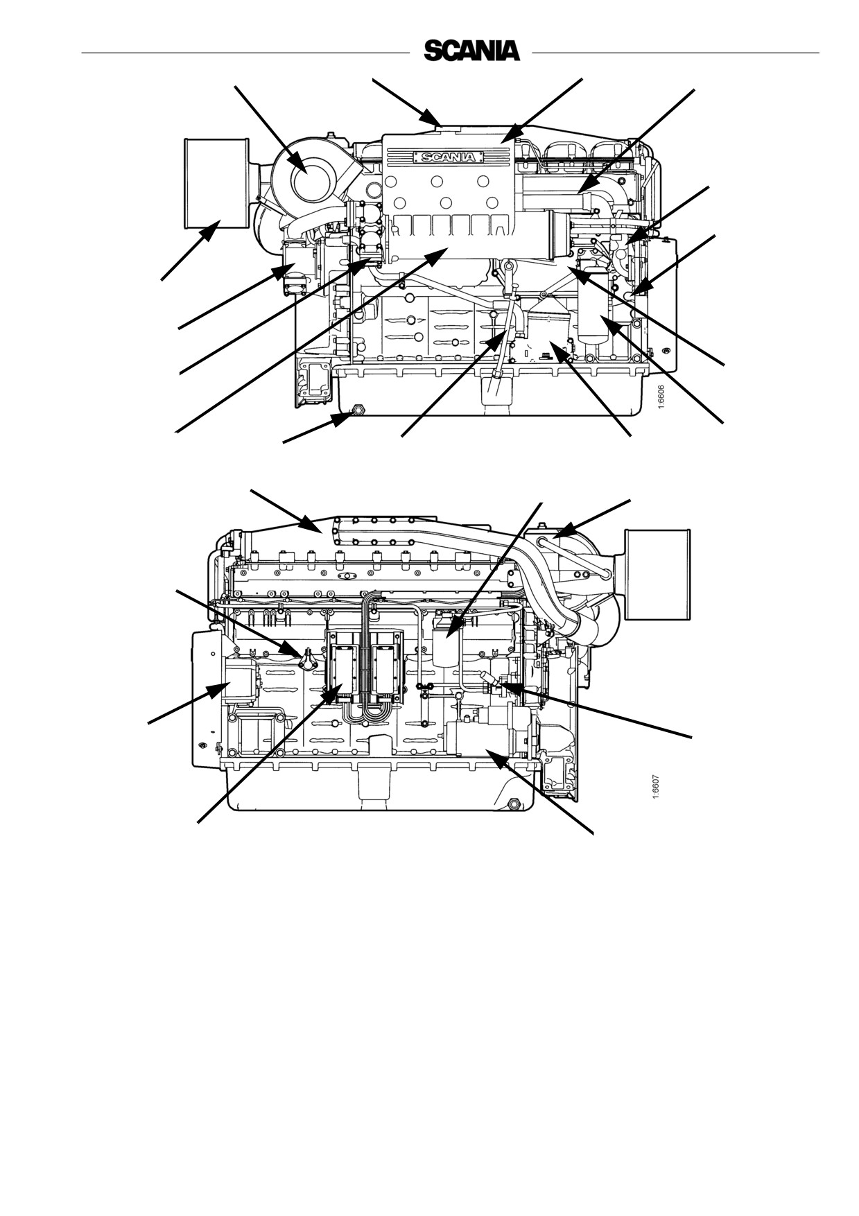
The illustrations show a normal version of a DI12-engine
Your engine may have different equipment from the one illustrated
1. Expansion tank
9. Oil dipstick
18. Closed crankcase
ventilation filter
2. Engine serial number,
10. Draining, engine oil
19. Fuel pump with hand pump
stamped into the cylinder
11. Heat exchanger
block
20. Starter motor
12. Sea water outlet
21. Control unit
3. Type plate
13. Sea water pump with sea
water inlet
22. Alternator
4. Coolant pump
14. Air filter (disposable)
23. Oil pressure sensor
5. Draining, coolant
15. Turbocharger
24. Charge air cooler
6. Oil cooler
16. Filling coolant
7. Oil filter
17. Fuel filter
8. Centrifugal oil cleaner
11
EMS engine management system
This engine has an electronic management system, EMS (Engine
Management System), with unit injectors (PDE) which provide each cylinder
with the right amount of fuel at the right time in all operating situations.
The EMS system consists of a control unit (S6) and sensors for speed, charge
air temperature and pressure, coolant temperature, oil pressure, accelerator
pedal/throttle actuation which constantly emit signals to the control unit.
With the aid of this input data and the programmed control software, the
correct fuel amount and correct injection time are calculated for each unit
injector (PDE) under the specific operating conditions.
The EMS system sensors can also be used to emit signals to the instruments
in the instrument panel.
The control unit constantly checks the sensors to make sure they are
operational.
The control unit contains monitoring functions to protect the engine in the
event of a fault which would otherwise damage it. In the event of a fault, e.g.
alarm level for low oil pressure or high coolant temperature, the S6 control
unit sends a CAN message to a coordinator.
The main task of the coordinator is to pass on data by means of CAN
communication from the engine control unit to other control units and signals
to gauges and lamps in the instrument panel. The coordinator also has
monitoring functions.
When the EMS control unit or the coordinator detects a fault, the diagnostics
lamp on the instrument panel(s) comes on, and it stays on as long as the fault
is active. At the same time, a fault code is generated which can be read off via
the coordinator on the diagnostics lamp in the form of a flash code when the
diagnostics switch is activated. A flash code may consist of a number of
different fault codes.
Diagnosis and troubleshooting using Scania EMS Display is described in the
Operator’s Manual for Scania Instrumentation.
If the torque reduction function is activated, the amount of fuel and the engine
power output are reduced to 70%, and if the engine shutdown function is
activated, the engine is switched off at programmed alarm levels.
A separate PC-based diagnostics program is used to read off the contents of
the flash codes. For an in-depth analysis of fault codes, contact an authorised
Scania dealer.
Reading off the fault codes, and descriptions of these, are also covered in a
separate document in the workshop manual, Engine Management System
EMS-S6: Troubleshooting.
Only authorised personnel are allowed to carry out diagnostic procedures and
program changes.
The positions of the sensors which emit signals to the control unit are shown
in the illustrations on page 13.
See pages 14 and 18 for a description of how to read off flash codes.
See pages 15 and 17 for a list of flash codes for the control unit and
coordinator.
12
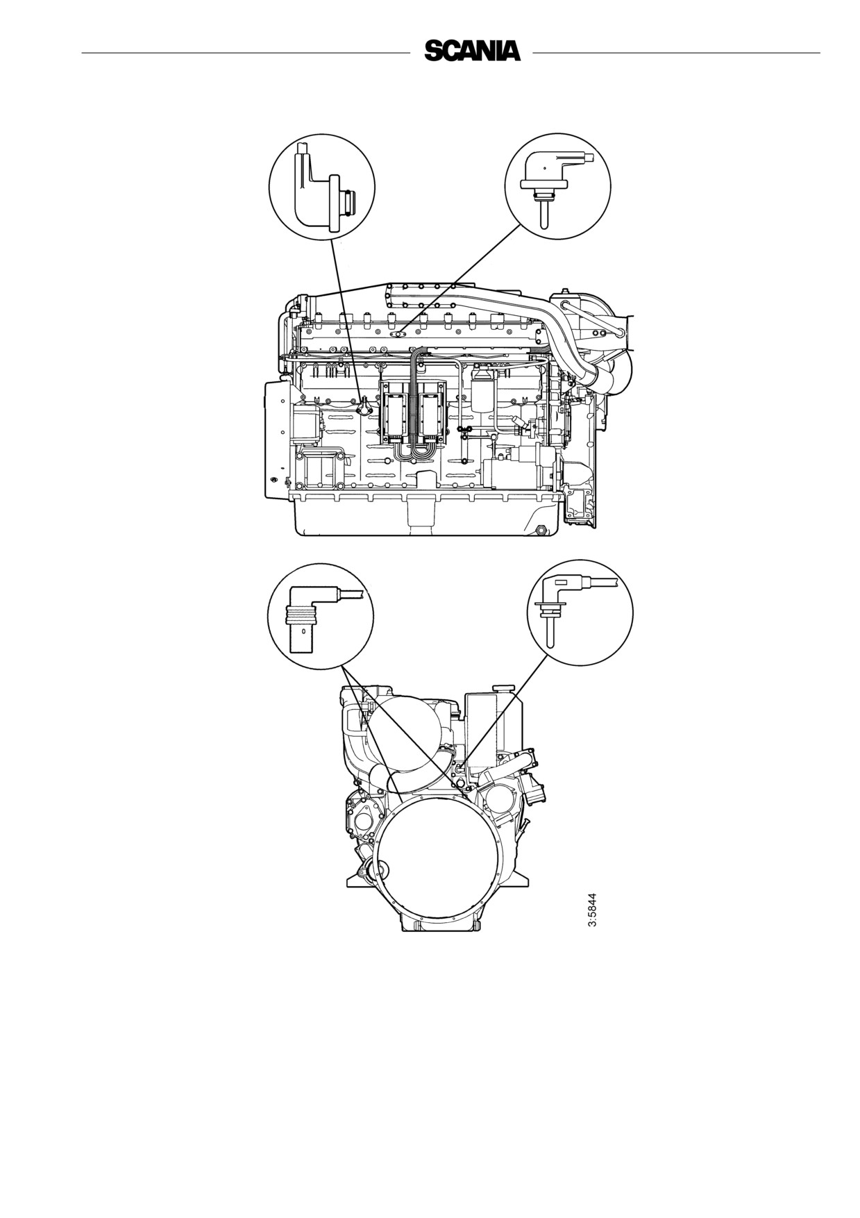
Positions of sensors for EMS with S6 on DI12
1
2
4
3
1. Oil pressure sensor
2. Charge air temperature and pressure
sensor
3. Coolant temperature sensor
4. Engine speed sensor (2)
13
Troubleshooting using flash codes for the EMS
control unit
• The diagnostics lamp on the instrument panel(s) always comes on for
two seconds when the system is powered up.
• As soon as a fault is detected by the control unit, it is stored in the
EEPROM fault code memory and the diagnostics lamp on the
instrument panel(s) comes on.
• The diagnostics lamp will stay on for as long as a fault is active. Even
if the lamp has gone off and the fault is no longer active, the code can
generally be read off by following the instructions below.
Reading off control unit fault codes
1. Turn on the ignition.
2. Activate the diagnostics switch to the left to view the flash codes for the
control unit (EMS).
3. A fault code will then flash on the diagnostics lamp. This flash code
consists of long flashes (approximately 1 second long) and short flashes
(0.3 seconds long). Long flashes are equivalent to tens and short flashes
to ones.
Example: long - short - short = fault code 12.
4. Repeat this procedure until the first flash code is repeated. This means
that the entire fault code memory has been flashed out. If the fault code
memory is empty, only one long flash approx. 4 seconds long will be
given.
5. See the flash code table on the next page for a description and to locate
the fault.
6. In order to obtain further information about the fault code, the PC-based
diagnostics tool or Scania EMS Display must be used. Contact an
authorised Scania workshop.
7. When a fault has been rectified the fault code can be erased as described
below.
Clearing fault codes (flash codes)
1. Switch off the ignition. If dual instrumentation has been fitted, the
ignition must be switched off on both panels.
2. Activate the diagnostics switch in the same direction as the flash codes
indicate, i.e. to the right for the coordinator (COO) or to the left for
EMS.
3. Switch on the ignition and at the same time keep the diagnostics switch
activated, to the right (COO) or to the left (EMS), for 3 seconds.
4. This will erase passive fault codes which can be read via flash codes for
the relevant system. The rest of the fault codes will remain in the
EEPROM and can only be deleted using the PC tool.
14

Overview of flash codes for the EMS control unit
Code
Description
Code
Description
PDE in cylinder 3: The solenoid valve is not
0
No fault detected.
53
working properly.
Engine overspeed. One or both engine speed
PDE in cylinder 4: The solenoid valve is not
11
sensors are indicating speeds in excess of
54
working properly.
3,000 rpm.
Rotational speed sensor 1 faulty, or incorrect
PDE in cylinder 5: The solenoid valve is not
12
55
signal.
working properly.
Rotational speed sensor 2 faulty, or incorrect
PDE in cylinder 6: The solenoid valve is not
13
56
signal.
working properly.
Coolant temperature sensor faulty, or incorrect
PDE in cylinder 7: The solenoid valve is not
14
57
signal.
working properly.
Charge air temperature sensor faulty, or incorrect
PDE in cylinder 8: The solenoid valve is not
15
58
signal.
working properly.
Charge air pressure sensor faulty or incorrect
16
59
Incorrect signal in extra analogue input.
signal.
17
Oil temperature sensor faulty, or incorrect signal.
61
Incorrect control unit shutdown.
18
Oil pressure sensor faulty, or incorrect signal.
66
Shutdown due to coolant level.
21
Coolant level sensor faulty.
68
Alternator charging incorrectly
23
Internal fault code in the coordinator.
69
Starter motor function interrupted or not activated.
Accelerator pedal/brake. If the accelerator and
24
82
Engine speed above ref. engine speed at start
brake pedals have been operated simultaneously.
Accelerator pedal sensor/idling switch
25
83
Fault in memory circuit (EEPROM) in control unit.
Accelerator pedal sensor/kickdown switch
Data transfer to the control unit memory
27
Engine shutdown bypassed.
84
(EEPROM) has been interrupted.
28
Shutdown due to oil pressure.
85
Incorrect internal temperature in the control unit.
Internal fault in the control unit: Fault in hardware
31
Torque limitation due to oil pressure
86
control.
32
Incorrect parameters for limp home function.
87
Fault in control unit RAM.
33
Battery voltage incorrect or no signal.
88
Internal control unit fault: Memory fault
Emergency stop switch activated in accordance
37
89
Defective seal: Prohibited changes in software.
with CAN message from coordinator.
43
CAN circuit faulty in the control unit.
93
Rotational speed sensors faulty or not connected.
47
Immobiliser function. Starter key code incorrect.
94
Shutdown due to high coolant temperature.
CAN message from the coordinator incorrect or
48
96
Torque limitation due to high coolant temperature.
missing.
Incorrect CAN version in control unit or
49
98
Incorrect voltage supply to one of the sensors.
coordinator.
PDE in cylinder 1: The solenoid valve is not
51
99
Internal hardware fault in the processor (TPU).
working properly.
PDE in cylinder 2: The solenoid valve is not
52
working properly.
15