Scania DI12. Marine engine. Operator’s manual - part 4

20. Every 1200 hours:
CHECKING THE COOLANT LEVEL
MONITOR
(optional equipment)
Note Check the coolant level monitor when the engine is cold.
1. Loosen the coolant level monitor cable clamps towards the cable cluster
and disconnect the connector.
2. Put a container under the water-cooled exhaust manifold and unscrew
the monitor. Immediately insert a threaded plug M18x1.5 in the hole for
the monitor. Avoid contact with the skin when handling coolant.
3. Connect the monitor connector and put the control switch in the "ON"
position.
4. Check that the warning lamp remains on and that the buzzer sounds (if
fitted).
5. Lower the monitor into a metal container (steel) with liquid. It is
important that the monitor body is in contact with the metal.
6. After approximately 2 seconds the warning lamp should go out.
7. Remove the monitor from the liquid. After approximately 7 seconds the
warning lamp will come on and the buzzer sound (if fitted).
8. Disconnect the monitor connector and screw on the monitor again.
9. Clamp the monitor cable as before and connect the connector.
10. Top up the system with coolant according to the specification on page
36.
48

21. Every 1200 hours:
CHECKING THE TEMPERATURE
MONITOR
1. Drain the coolant, allowing the temperature monitor to be removed.
2. Remove the temperature monitor cable(s).
3. Unscrew the monitor.
4. Refit the cable(s) to the monitor.
C =Common connection
5. Submerge the monitor sensor body in water. Heat the water slowly
1 = Connection C -1 closes at the
(approx. 1° minute) using e.g. an immersion heater.
stamped temperature
6. Set the control switch to "ON". Use a thermometer to check that the
2 =Connection C -2 opens at the
warning lamp comes on or that an alarm is initiated at the correct
stamped temperature
temperature.
2-pole temperature monitor
The correct temperature is stamped on the hexagonal part of the
monitor.
The temperature tolerance is ± 3°.
CHECKING THE TEMPERATURE
Always use a suitable container
SENSOR
to avoid spillage when
draining coolant.
1. Drain the coolant, allowing the temperature sensor to be removed.
Dispose of used coolant through
2. Remove the temperature sensor cable(s).
an authorized waste disposal
3. Unscrew the sensor.
contractor.
4. Connect an ohmmeter to the temperature sensor.
5. Submerge the sensor body in water. Heat the water slowly
(approximately 1° per minute) using e.g. an immersion heater.
6. Check the resistance at the temperatures given below.
7. The sensor should give the following readings:
At temp. °C
Resistance Ω
Tolerance °C
2-pole temperature sensor
60
134 ± 13.5
±4
90
51.2 ± 4.3
±3
100
38.5 ± 3
±3
49

22. Every 1200 hours:
CHECKING THE OIL PRESSURE
SENSOR/MONITOR
Sensor function
Measure the sensor output voltage (pin 3) at different oil pressures. The
sensor output voltage shall be as follows:
0.85-1.15 bar
=
2.45 volt
1.80-2.20 bar
=
3.70 volt
2.75-3.25 bar
=
4.50 volt
3.79-4.20 bar
=
5.20 volt
4.55-5.45 bar
=
5.70 volt
5.40-6.6 bar
=
6.10 volt
The tolerances apply at +30°C - 110°C. At lower temperatures the tolerance
range is wider, e.g. 0°C = x 1.4.
4
1
Monitor function
Connect a test lamp to the oil pressure monitor, pin 4 (- ground), and check
that the monitor switches on at the correct pressure when the engine is started
and stopped. The monitor shall switch on at 0.7 ± 0.15 bar when the engine is
3
stopped.
2
Important The sensor/monitor must be supplied with voltage during the
measurement. Maximum 4 W load from a test lamp.
CHECKING THE OIL PRESSURE
MONITOR FOR DEC 2
Connect an ohmmeter or a test lamp to the oil pressure monitor and check
that the monitor switches off/on at the correct pressure when the engine is
started and stopped. The monitor shall switch off at 1.1 ± 0.15 bar when the
engine is started and switch on at 0.7 ± 0.15 bar when the engine is stopped.
50
RENEWING THE BATTERY
Removal
Do not connect the cables to the
1. Disconnect the negative cable (-) from the battery (cable connected to
wrong terminals.
ground).
This could cause serious
2. Disconnect the positive cable (+) from the battery (cable connected to
damage to the electrical system.
starter motor).
If the terminals are short-
Fitting
circuited, sparks will be
generated.
1. Connect the positive cable (+) to the battery (cable connected to starter
motor).
2. Connect the negative cable (-) to the battery (cable connected to
ground).
Dispose of used batteries
through an authorized waste
disposal contractor.
MISCELLANEOUS
23. Every 1200 hours:
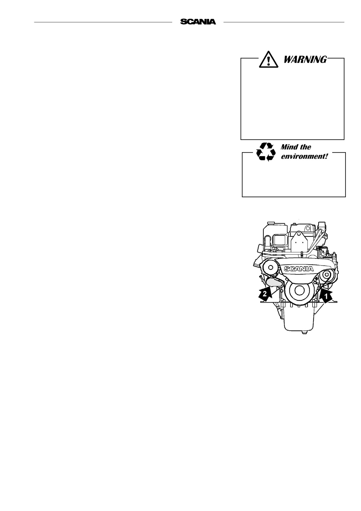
CHECKING THE DRIVE BELT
Replace the drive belt (1) (poly V-belt) if worn or damaged.
Also check that the automatic belt tensioner (2) is working and keeps the
drive belt correctly tensioned.
51

24. Daily:
CHECKING FOR LEAKAGE, RECTIFY
AS NECESSARY
- Start the engine.
- Check for oil, coolant, fuel, air and exhaust leakage.
- Tighten or change leaking connections. Check the overflow holes (1)
(below the side covers) which show whether the O rings between the
Ensure that any leakage does
cylinder liners and crankcase are leaking, refer to illustration.
not pollute the environment.
a) If coolant is evident, the O-ring is leaking.
b) If oil is running out, the liner shelf is leaking.
- Check that the coolant pump drain hole (2) is not clogged, refer to
illustration. If there is leakage, renew the pump seal or the coolant pump
assembly.
A small amount of leakage from the overflow holes during the engine
In case of major leakage,
running-in period is normal. (Seals and O-rings are lubricated with soap
contact the nearest Scania
or oil when fitted).
workshop.
This leakage normally stops after a time.
52
25. Every 2400 hours:
CHECKING/ADJUSTING VALVE
Immobilise the starting device
CLEARANCE
when working on the engine.
Note: Checking/adjusting valve clearance should also be done after the
If the engine starts out of
first 400 hours of operation.
control, there is a
Valve clearances should be adjusted when the engine is cold, at least 30
SERIOUS RISK
minutes after running.
OF INJURY.
The rocker cover gaskets should be changed as necessary. Tightening torque:
26 Nm.
Intake valve clearance: 0.45 mm
Outlet valve clearance: 0.70 mm.
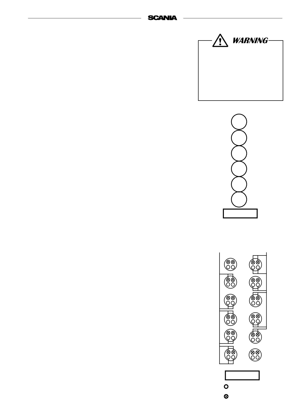
1
Alternative 1
- Position No. 1 cylinder at TDC by turning the crankshaft in its normal
2
direction of rotation until all four valves are closed.
- Adjust the following valves. The correct valve clearance is also stated
3
on the instruction plate on one of the valve covers:
Cylinder
1
Intake and outlet
4
2
Intake
5
3
Outlet
4
Intake
6
5
Outlet
FLYWHEEL
- Position No. 6 cylinder at TDC by turning the crankshaft one revolution
in its normal direction of rotation and adjust the following valves:
Cylinder numeration
Cylinder
2
Outlet
TDC
TDC
3
Intake
no. 6 cylinder
no. 1 cylinder
4
Outlet
5
Intake
6
Intake and outlet
FLYWHEEL
Intake valve
exhaust valve
53

Alternative 2
- Position No. 1 cylinder at TDC by turning the crankshaft in its normal
direction of rotation until all four valves are closed.
- Adjust all valves for No. 1 cylinder. Correct valve clearances are
indicated on the instruction plate on one of the rocker covers.
- Proceed in the same way for the remaining cylinders in the sequence
5 - 3 - 6 - 2 - 4 (firing order) by turning the crankshaft 1/3 of a revolu-
tion in its normal direction of rotation after each adjustment.
Note:
Readings can be taken from the
flywheel through covers in the
flywheel housing either from
above or underneath depending
on access when fitting.
It says up and down respectively
on the flywheel
Both covers are fitted with a
cover at delivery.
Covers for reading
on the flywheel housing
26. Every 2400 hours:
CHANGING (or CLEANING) THE
CLOSED CRANKCASE VENTILATION
VALVE.
Alternative 1:
Change the valve at the specified interval.
Alternative 2:
- Remove the valve after the specified interval.
- Clean the valve by placing it in a bath of diesel oil overnight. Then rinse
it several times in diesel oil and allow it to drip dry.
- Refit the valve.
- The valve may be reused (cleaned), maximum twice after the initial
2400 hours of operation. Take care to mark the valve after cleaning it.
54
LONG-TERM STORAGE
If the engine is not to be used for a lengthy period of time, special measures
should be taken to protect the cooling system, fuel system and combustion
chamber from corrosion and the exterior from rusting.
The engine can normally stand idle for up to six months. If it remains unused
for longer than this the following measures, which provide protection for
about four years, should be adopted. An alternative to preparing the engine
for long-term storage is to start the engine and warm it up every 6 months.
Preparing the engine for long-term storage means:
- Thoroughly cleaning the engine
- Running the engine for a certain time using special preservative fuel, oil
and coolant.
- Otherwise preparing the engine for storage (filter changes, lubrication,
etc.).
Preservative coolant
If the engine is to be stored with a full cooling system, use coolant containing
50% glycol by volume. Glycol without nitrite-based inhibitor must be used.
E.g. BASF G48 or BASF D542.
Ethylene glycol, if swallowed
Preservative fuel
can be fatal.
- Use diesel fuel oil mixed with Lubrizol 560A or the equivalent.
Avoid contact with the skin.
- Mix 1 cm3 (ml) of Lubrizol 560A with 10 dm3 (l) of fuel.
!
HANDLING LUBRIZOL 560A
Hazardous!
Contains aromatic hydrocarbons
Use spot extractors where there is a danger of vapour build-up.
Wear protective gloves and goggles when handling Lubrizol. Do not use contaminated clothing.
In case of splashes in the eye: Rinse with moderate water spray (for min. 15 minutes). Seek medical attention.
In case of skin contact:
Wash affected areas with soap and water.
If you inhale it:
Fresh air, rest and warmth
Flammable:
Fire class 2A. Flash point + 27°.
In case of fire: Extinguish using carbonic acid, powder or foam
Storage:
In properly sealed container in a dry, cool place. Keep out of reach of children.
55
Preservative oil
Suitable preservative oil can be supplied by most petroleum companies.
E.g. Dinitrol 40 or the equivalent.
Preparations for storage
-
Drain and flush the cooling system. Top up with preservative coolant.
Always use suitable containers
-
Warm up the engine on regular fuel. Stop the engine and drain the oil.
to avoid spillage when
draining oil and coolant.
-
Change the fuel filter and turbo filter.
Dispose of used oil and coolant
-
Fill the engine with preservative oil up to the minimum level on the
through an authorized waste
dipstick.
disposal contractor.
-
Mix preservative fuel in a can. Detach the fuel pipe at the feed pump
suction line and connect a hose from the can.
-
Detach the fuel pipe at the overflow valve and connect a return hose to
the can.
-
Start the engine and run it at approximately 1000 rpm (not single-speed
engines) for 20-25 minutes.
-
Stop the engine, remove the hoses and connect the normal fuel lines.
-
Oil the valve mechanism generously with preservative oil.
-
Remove the injectors and spray preservative oil into each cylinder,
maximum 30 cm3 (ml).
Turn the engine over a few revolutions using the starter motor. Spray an
additional small amount of oil into each cylinder.
After this the engine must not be cranked. Refit the injectors.
-
Drain the preservative oil from the engine. Fresh engine oil can be filled
directly or when the engine is taken out of storage.
-
Drain the coolant if the engine is not to be stored with a full cooling
system. Plug and tape over all coolant connections (if the cooling system
is not completely assembled).
-
Air cleaner: Clean or renew the filter element.
-
Cover air intakes and exhaust pipes.
-
Alternator and starter motor:
-
Spray with water-repellent anti-corrosive oil, CRC 226, LPS1 or equal.
-
Spray the outside of bright metal engine parts, first with penetrating pre-
servative oil such as Dinitrol 25B and then with Dinitrol 112 or equal.
Winter storage
- In order to minmize the risk of condensation water in the fuel tank
during a winter stop, it should be filled with fuel.
56
- Attach a label to the engine showing the date of preservation and
clearly stating that it must not be started or cranked.
STORED ENGINE
Date
Do not start or crank!
Batteries
Remove the batteries for trickle charging at a charging station. (Does not
apply to batteries, which the manufacturer specifies to be maintenance free).
Wear gloves and eye protection
The same is applicable for short-term storage if the engine has not been
prepared for storage as above.
when charging and handling
batteries.
Storage
Batteries contain a highly
After the preparations, the engine should be stored in a dry and warm place
corrosive acid.
(room temperature).
Taking out of storage
(Procedure when the engine is to be put into operation)
- Remove plugs and tape from coolant connections, air intakes and
exhaust pipes.
- Fill the cooling system with coolant, refer to page 22.
Always use suitable containers
- Check the oil level in the engine or fill up with fresh motor oil.
to avoid spillage when
- Turn the engine over a few times with the injectors removed, at the same
draining oil and coolant.
time copiously oiling the valve mechanism with pushrods and tappets.
Dispose of used oil and coolant
Important The engine must be cranked with the injectors removed so that
through an authorized waste
surplus preservative oil will be pressed out of the cylinders.
disposal contractor.
- Fit the injectors.
- Empty the fuel system's main filter of preservative oil.
- Bleed the fuel system, refer to page 45.
- Wash off any externally applied preservative oil, using white spirit.
57

TECHNICAL DATA
GENERAL
DI12
Number of cylinders
6 in line
Cylinder diameter
mm
127
Stroke
mm
154
Displacement
dm3 = (litre)
11.70
Number of main bearings
7
Firing order
1 - 5 - 3 - 6 - 2 - 4
Compression ratio
15:1 (or 13.5:1)
Engine direction of rotation viewed from rear
Anticlockwise
Cooling
Liquid
Valve clearances, cold engine
intake valve
mm
0.45
exhaust valve
mm
0.70
Weight, without coolant or oil
engine with heat exchanger
kg
1130
engine without heat exchanger (keel
1070
cooling engine)
kg
Power output
see engine card, "Engine record card"
LUBRICATION SYSTEM
Max. oil pressure
(warm engine at speed above 800 rpm)
bar (kp/cm2)
6
Normal oil pressure
(warm engine at operating speed)
bar (kp/cm2)
3 - 6
Min. oil pressure
(warm engine 800 rpm)
bar (kp/cm2)
0,7
Oil capacity, see page 31
Crankcase pressure with closed crankcase
mm VP
-55 - +20
ventilation
58

FUEL SYSTEM
DI12
Pump setting BTDC
See plate on rocker cover
Injectors, opening pressure
bar (kp/cm2)
300
Low idle
rpm
700
Maximum full load speed
See engine card
Fuel
Diesel fuel oil1
Tightening torques:
Socket nut for injectors
Nm
70
Cap nut for delivery pipe
Nm
20
Oil leakage connection
Nm
11
1 see page 60
COOLING SYSTEM
Number of thermostats
1(dual thermostat)
Thermostat, opening temperature
°C
83
Coolant temperature:
System with barometric pressure
°C
70 - 93
System with overpressure
°C
70 - approx. 100
Volume
with heat exchanger
dm3 = (litre)
appr. 40
without heat exchanger (keel
appr. 24
cooling engine)
dm3 = (litre)
ELECTRICAL SYSTEM
System voltage
V
24
Alternator, current
A
65 (2-pin) or 90 (1-pin)
Starter motor power
kW (hp)
6.7
(9.1)
Monitors, alarm values:
Oil pressure monitor
bar (kp/cm2)
0.7 ± 0.15
Temperature monitor
°C
Stamped on hexagonal part of monitor
59

FUEL
Diesel fuel
The composition of the diesel fuel is vitally important to the operation and
life of the engine and the fuel injection pump. The engine power output and
the exhaust emissions are also dependent on the fuel quality. The
requirements and the test standards for the most important properties are
described in the workshop manual in sections that can be ordered from your
Scania dealer or directly from Scania. The address of Scania is printed on the
cover.
The diesel fuel shall comply with the following standard: EN 590 (European
standard).
The table below shows the requirements for some of the most important
properties:
Property
Requirement
Viscosity at 40°C
2.0 - 4.5 mm2/s (cSt)
Density at 15°C
0.82 - 0.86 kg/dm3
Sulphur (concentration by mass)
max. 0.3%
Ignitability (CET rating)
min. 49
Flashpoint
56°C
Environmentally favourable fuels (low sulphur fuels)
There are three different grades of so called environmentally favorable fuels
(SS15 54 35). Grade 1 is sulphur-free and grade 2 is low in sulphur.
Compared with class 3 (normal fuel), these fuels are less dense and this
reduces engine power output. Only class 1 fuel should be used with a
catalytic converter.
Short term use of fuel with a higher sulphur content than 0.05% by weight
will not cause permanent damage to the catalytic converter.
The catalytic converter may, however, require fuel with low sulphur content
for some time after this to regain its normal efficiency.
60
Temperature dependence of diesel fuel
At temperatures lower than those specified for the diesel fuel, paraffin wax
may precipitate from the fuel and block filters and pipes. The engine can then
loose power or stop.
The diesel fuel is adapted for use in the specific climate of each country. If a
It is not permitted to mix
vehicle or an engine is to be operated in a temperature zone with lower
kerosene with diesel fuel that is
temperature than normal, first identify the temperature properties of the
already adapted for the climate
fuel concerned.
concerned. The injection pump
The properties of the fuel when cold can be improved by adopting one of the
may be damaged. All use of
following measures before the temperature drops:
paraffin other than kerosene is
- If the fuel concerned is not intended for the expected temperature and no
forbidden, as it causes engine
diesel fuel with the correct temperature properties is available, we
damage.
recommend that an electric fuel heater be installed as a preventative
measure.
- The low temperature properties of diesel fuel may be improved by
adding kerosene as a preventative measure. A maximum of 20% may
be added. When refuelling, the kerosene should be added first, so that it
mixes thoroughly with the diesel fuel.
It is not permissible to mix
Note: It is prohibited to use kerosene in engine fuel in some countries.
petrol with diesel fuel. Petrol
- To prevent water in the fuel from freezing and forming ice, maximum
may cause wear to the fuel
0.5-2% alcohol (isopropanol) may be added.
injection pump and it may also
Drain fuel tanks and drain or renew fuel filters at regular intervals.
cause damage to the engine.
61
ALPHABETICAL INDEX
Air cleaner
42
Leakage
52
Air cleaner, prefilter
42
LED functions
18
Air cleaner, safety cartridge
44
Lubricating oil pressure sensor/monitor
50
Air filter, element
42
Lubricating oil system
30
Lubrication pressure
26
Batteries
47
Battery, renewing
51
Maintenance
28
Bleeding, fuel system
45
Maintenance schedule
29
Certified engines
5
Oil analysis
30
Checks after running
27
Oil capacity
31
Checks before running
23
Oil change
31
Clutch
27
Oil cleaner
32
Coolant
36
Oil filter
34
Coolant level
34
Oil grade
30
Coolant level monitor
48
Oil level
31
Coolant temperature
25
Oil pressure
26
Coolant temperature monitor
49
Oil pressure monitor, DEC2
50
Coolant temperature sensor
49
Coolant, changing
38
Prefilter, air cleaner
42
Cooling system
34
Preparations for storage
55
Cooling system, cleaning
39
Corrosion inhibitor
38
Running
25
DEC2 Control system
16
Safety cartridge, air cleaner
44
Drive belt
51
Safety details
10
Safety precautions for care and maintenance . 12
Electrical system
47
Safety precautions for handling materials . . . 12
Engine speed
25
Safety precautions for operation
11
Environmental responsibility
4
Starting the engine
23
Start-up report
1
Fault codes DEC2
20
Stopping the engine
26
Filter, air cleaner
42
Storage
57
Filter, fuel
45
Foreword
2
Taking out of storage
57
Fuel filter, renewing
45
Temperature monitor
49
Fuel level
45
Troubleshooting DEC2
19
Fuel specifications
60
Fuel system
45
Vacuum indicator
42
Fuel system, bleeding
45
Valve clearance
53
Glycol
36
Warranty
1
Injector
46
62