Scania DI12. Marine engine. Operator’s manual - part 3
3. Every 400 hours:
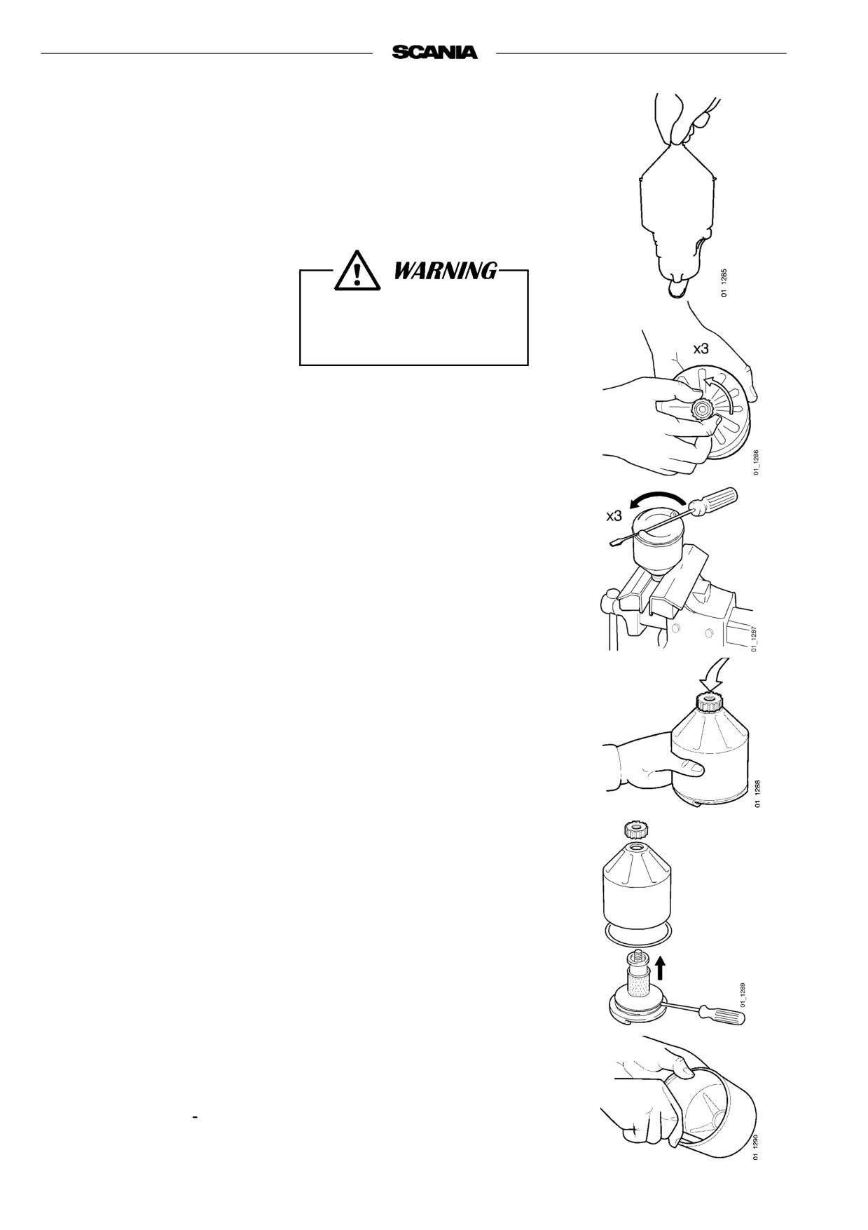
CLEANING THE OIL CLEANER
(at same time as an oil change)
- Unscrew the nut and remove the cover.
Open the cap carefully. The
oil may be hot.
- Lift out the rotor and loosen the nut on the rotor bowl three turns.
- If the nut is jammed:
Clamp the nut, not the rotor, in a vise and turn the rotor three
revolutions by hand or using a screwdriver.
- Tap the nut lightly with your hand or a plastic hammer, to detach the
rotor bowl from the bottom plate.
- Unscrew the nut and remove the rotor bowl.
- Prize carefully to detach the strainer from the bottom plate.
- Scrape off the deposits from the inside of the rotor bowl. If there are no
deposits, this indicates that the cleaner is not working properly.
- If the deposits are thicker than 20 mm: clean more frequently.
32

- Rinse all parts in diesel fuel.
- Fit the O-ring in the rotor bowl. Make sure it is not damaged.
Renew parts if necessary.
- Assemble the rotor.
- Tighten the rotor nut firmly by hand
- Refit the rotor.
- Make sure that it spins easily.
- Check that the O-ring in the bowl is undamaged.
Renew the O-ring if hard or damaged.
- Secure the bowl firmly, tightening the nut
If the nut is tightened with a tool, the rotor shaft, nut or bowl may be
damaged.
Operational test
The rotor rotates very fast and should continue to turn when the engine has
stopped.
- Stop the engine when it is warm.
- Listen for a whirring sound from the rotor or feel whether the cleaner
housing is vibrating.
The rotor normally continues spinning for 30 - 60 seconds after the engine
has stopped.
If not: dismantle and inspect.
33

4. Every 400 hours:
RENEWING THE OIL FILTER
(at same time as an oil change)
- Remove the old filter.
- Oil the rubber gasket and fit a new genuine Scania filter.
- Tighten the filter by hand.
Never use a tool for tightening. The filter could be damaged,
obstructing circulation.
- Start the engine and check for leaks.
Important If the deposits in the centrifugal cleaner are thicker than 20
mm the oil filter should be renewed more frequently. This
includes cleaning the centrifugal filter and changing oil.
Always collect oil in a suitable
container to avoid spillage when
renewing the oil filter.
Dispose of used filters through
an authorized waste disposal
contractor.
COOLING SYSTEM
5. Daily:
CHECKING THE COOLANT LEVEL
- Open the expansion tank filler cap and check the coolant level.
- Open the expansion tank filler cap and check the coolant level.
Carefully open the cap.
Hot water and steam
- Correct level: (integral expansion tank in the heat exchanger)
may blow out.
- Cold engine: The coolant level should be 10 - 20 mm under the
expansion tank upper inner part.
- Warm engine:The coolant level should be at the expansion tank upper
inner part.
- Other types of expansion tank according to the instructions of the fitter.
- Top up the coolant as necessary, see point 6.
Always top up with ready mixed
coolant.
Note When filling large amounts of coolant:
Never pour cold coolant into a hot engine.
This could cause cracks in the cylinder block and the cylinder
head.
34
6. Var 400:e timme:
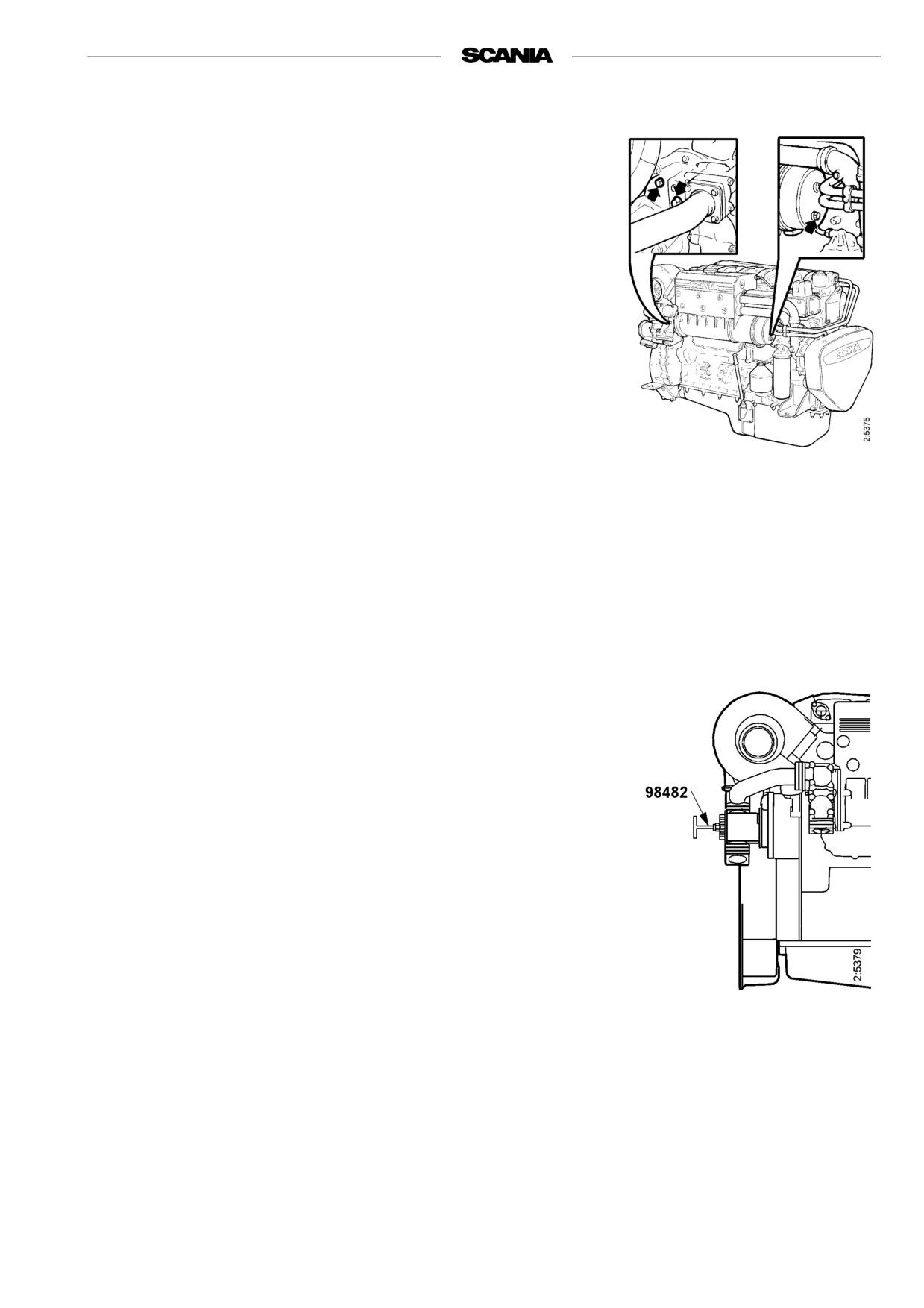
CHECKING CORROSION BARS
(Only engines with heat exchanger)
- Empty the sea water circuit and check the corrosion bars (protection
anodes). Located as illustrated.
- Scrape off all loose material on the anode.
- Change if less than half the bar is left.
A new bar is 55 mm long with a diameter of 17 mm.
Important If the corrosion bars are very corroded they need to be checked
more often, for example every 200 hours.
7. Every 400 hours:
CHECKING THE SEA WATER PUMP
IMPELLER
(Only engines with heat exchanger)
- Close the bottom valve if the seawater pump is below the water line.
- Empty the sea water circuit.
- Take off the seawater pump cap.
- Check that the impeller vanes are not worn or damaged.
Important If the impeller must be changed frequently, the cleaning of the
sea water must be improved.
Changing the impeller
- Pull out the impeller with puller 98 482 (Scania Special Tools).
- Fit new impeller and cap. Check that the cap seal is not hard or
damaged.
Note A spare impeller should be kept on board.
- The impeller can be deformed at longer periods of inactivity. Change
before or remove the impeller before longer periods of stoppage. Also
see "Preparations of storage".
35
8. Every 2400 hours:
CHECKING THE COOLANT
Coolant should be checked as follows:
Coolant composition:
a) Check the appearance of the coolant.
If there is a danger of freezing:
b) Coolant with only glycol: Check the glycol content.
minimum 30% glycol by
c) Coolant with only Scania Anti-corrosive:
volume
Check the corrosion inhibitor.
maximum 60% glycol by
volume
The composition of the coolant is described in detail under
If there is no danger of freezing:
"Starting and running"
7-12% by volume
Scania Anti-corrosive
a)
Checking the appearance of the coolant
- Fill a receptacle with a little coolant and check that it is clean and clear.
- If the coolant is contaminated or cloudy: consider changing the coolant
- Water added to the coolant should be clean and free from dirt of any
kind.
- Use drinking water with a pH of 6 - 9.
b)
Checking the glycol content
If there is a danger of freezing, use only glycol as an anti-corrosive in the
Ethylene glycol is highly
coolant.
dangerous if ingested and can
- Cooling systems with glycol should contain at least 30% glycol by
prove fatal.
volume to provide acceptable protection against corrosion.
Avoid skin contact with glycol.
- A content of 30% glycol by volume protects against freezing down to
-16°C. If further protection is needed, refer to the table on the next page
for calculating the required amount of glycol.
We recommend only nitrite-free anti-freeze glycol with the following
supplier designations:
The coolant should be ready
BASF G48 or BASF D542
mixed when it is poured into the
- Always top up the anti-freeze if its glycol content drops below 30% by
cooling system.
volume. A glycol content above 60% by volume will not provide greater
Never top up with only water or
protection against freezing.
only glycol.
- The table shows the temperature at which ice starts to form. The engine
will freeze and break at appreciably lower temperatures, see diagram.
- Ice forming in the coolant often causes malfunctioning without any risk
of damage. The engine should not be subjected to heavy loads when ice
starts to form.
The recommended glycol must
Note Change the coolant when cleaning the cooling system: Every 4800
not be mixed with glycol having
hours or minimum every 5 years.
nitrite-based anti-corrosive.
Important If a coolant filter is used in the cooling system, it must not con-
Risk for build up of sludge and
tain an inhibitor.
reduced cooling capacity.
36

% glycol by volume
Properties of glycol at low temperatures:
- Example with 30% glycol by volume
- Ice slush starts to form at -16°C.
- There is risk for malfunctions at -30°C
- No risk of damage by freezing with a
minimum content of 30% glycol by volume
Curve A: Ice build up starts (slush)
Curve B: Temperature at which damage due to
freezing can occur
1. Safe range
2. Malfunctions may occur (ice slush)
3. Risk of damage by freezing
A
% glycol by
Cooling
15
20
25
30
35
40
45
50
60
volume
system
capacity,
Ice slush starts
-6
-9
-12
-16
-22
-27
-36
-46
-55
dm3
to form at °C
5
6
8
9
11
12
14
15
18
30
6
8
10
12
14
16
18
20
24
40
8
10
13
15
18
20
23
25
30
50
9
12
15
18
21
24
27
30
36
60
11
14
18
21
25
28
32
35
42
70
12
16
20
24
28
32
36
40
48
80
14
18
23
27
32
36
41
45
54
90
15
20
25
30
35
40
45
50
60
100
Glycol dm3
17
22
28
33
39
44
50
55
66
110
(litres)
18
24
30
36
42
48
54
60
72
120
20
26
33
39
46
52
59
65
78
130
21
28
35
42
49
56
63
70
84
140
23
30
38
45
53
60
68
75
90
150
24
32
40
48
56
64
72
80
96
160
26
34
43
51
60
68
77
85
102
170
27
36
45
54
63
72
81
90
108
180
29
38
48
57
67
76
86
95
114
190
30
40
50
60
70
80
90
100
120
200
A= Area to be avoided. Only for calculating glycol mix.
Coolant freezing temperature when ice starts to form at different glycol mixes
37

c)
Checking the corrosion inhibitor
There must always be sufficient corrosive inhibitor in the coolant to protect
Corrosion inhibitor, if
the cooling system against corrosion.
swallowed can be fatal.
If there is no danger of freezing, only Scania Anti-corrosive should be used
Avoid contact with the skin.
in the coolant.
The inhibitor in Scania Anti-corrosive is free of nitrite.
The correct proportion of anti-corrosive is 7-12% by volume.
- Topping up with 1.0% Scania Anti-corrosive by volume should be done
Mixing corrosion inhibitor with
after every 2400 hours of operation.
glycol or adding too much
- Never top up with only water or only anti-corrosive!
corrosion inhibitor may cause
Fluid losses must always be replaced with premixed coolant:
deposits and reduced cooling
water + 10% by volume of Scania Anti-corrosive.
capacity.
Note The coolant should be changed when the cooling system is
cleaned: every 4800 hours or minimum every 5 years.
If a coolant filter has been fitted
it must not contain inhibitor.
Changing the coolant
1. Remove the filler cap from the expansion tank.
2. The coolant is drained at two points as illustrated:
- from the underside of the heat exchanger by removing two plugs.
- through a valve in the unit.
3. Close the valve and refit the plugs.
4. Top up with coolant through the expansion tank filler hole.
Mix coolant as described on page 36.
Always collect fluid in a suitable
container to avoid spillage when
changing coolant.
Dispose of used coolant through
an authorized waste disposal
contractor.
38
9. Every 4800 hours:
CLEANING THE COOLING SYSTEM
Note If necessary, the cooling system should be cleaned more often.
External cleaning
The cooling system must never
Heat exchanger
be cleaned with caustic soda.
1.
Drain the coolant from the engine and the heat exchanger, see
There is a risk of damage to
"Changing the coolant".
aluminium parts.
2.
Empty the sea water circuit and detach the heat exchanger sea water
inlet and outlet pipes.
3.
Detach the pipes to the charge air cooler and the charge air cooler
thermostat housing. Detach the pipe between the front cover and the
heat exchanger.
4.
Remove the connection housing on the coolant pump inlet and the return
Handle the heat exchanger
pipe to the pump.
housing with care as the
5.
Remove the thermostat housing and the outlet pipe from the engine.
material is aluminium.
6.
Remove the vent pipe from the expansion tank.
7.
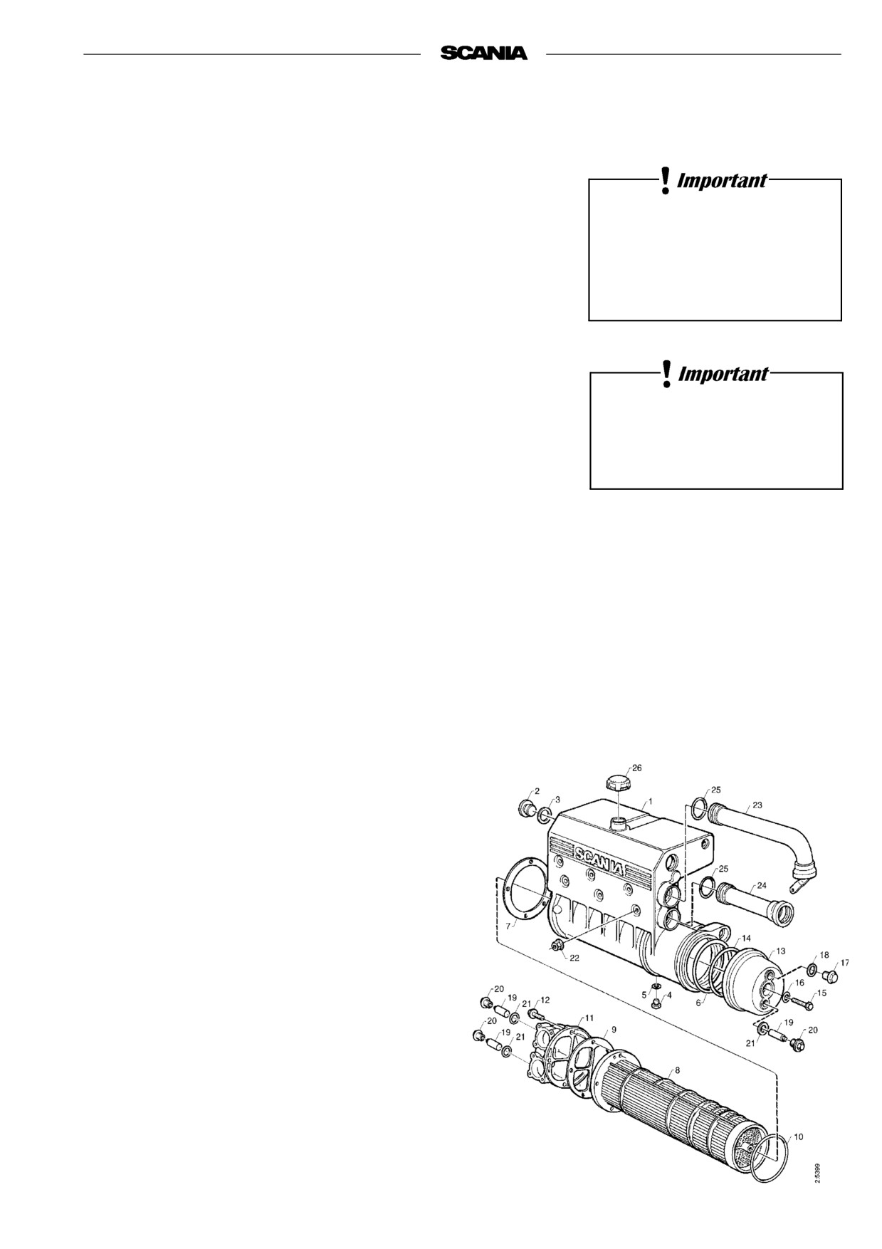
Remove the flange nuts and lift off the heat exchanger assembly.
8.
Remove the cap at the rear end and pull out the cooler core.
9.
Clean the outside of the core. Use a paraffin-based engine cleaner.
10.
Any deposits inside the pipes can be removed mechanically with a
round rod.
11.
Replace gaskets and O-rings. Grease and fit the O-ring 10 inside the
housing and reassemble the heat exchanger.
12.
Refit the heat exchanger assembly. Tighten the flange nuts to 50 Nm.
13.
Refit the inlet and outlet pipes, the thermostat housing, the coupling
housing and the charge air cooler pipes.
14.
Top up the system with coolant according to the specification on page
36.
1. Heat exchanger
16. Sealing ring
housing
17. Bolt
2. Plug
18. Sealing ring
3. Gasket
19. Protection anode
4. Plug
(3)
5. Gasket
20. Plug
6. O-ring
21. Sealing ring
7. Gasket
22. Flange nut
8. Cooler core
23. Return pipe to
coolant pump
9. Gasket
24. Outlet pipe from
10. O-ring
engine
11. Rear cover
25. O-ring
12. Bolt
26. Pressure cap
13. Front cover
14. O-ring
15. Bolt
39
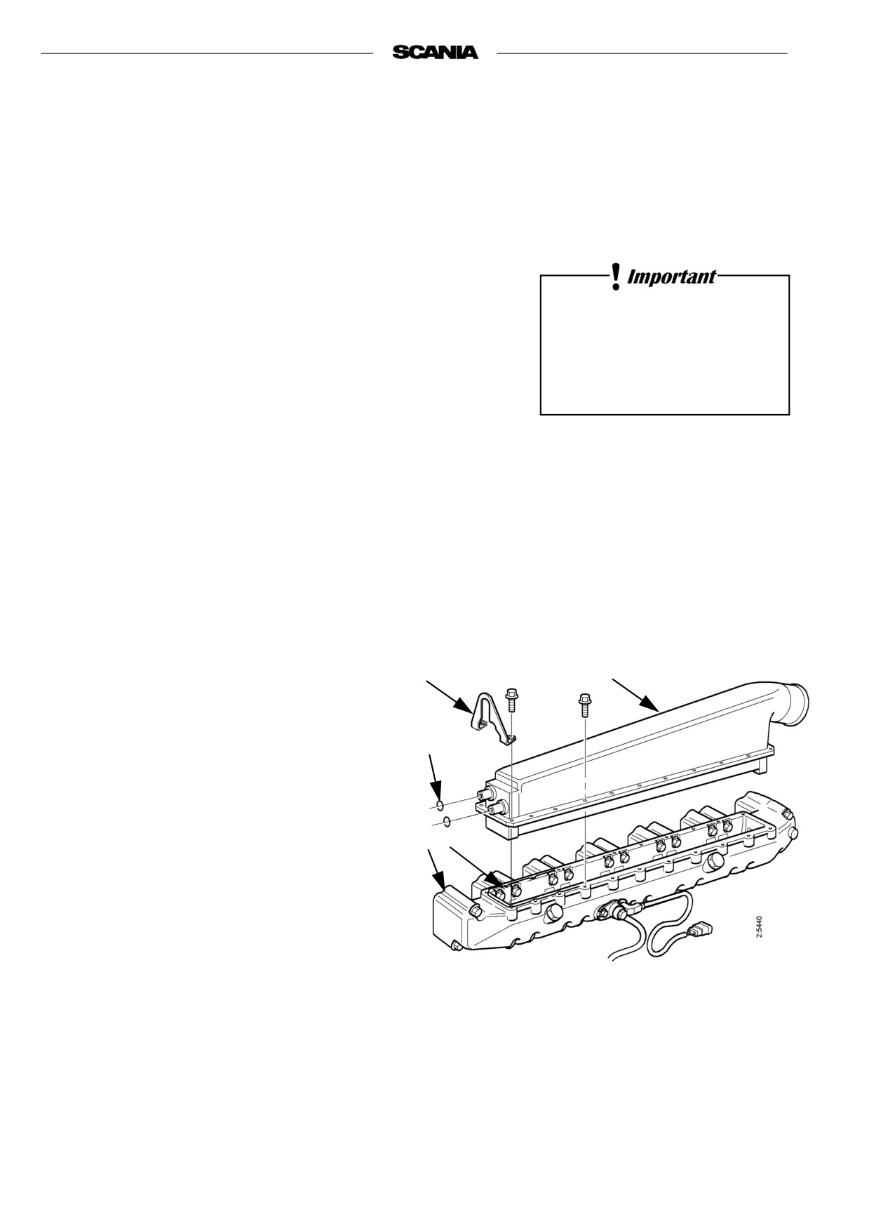
Charge air cooler
1. Drain the coolant from the engine, refer to "Changing the coolant".
2. Detach the intake manifold from the turbo.
3. Detach the charge air cooler inlet and outlet connections.
4. Unbolt the charge air cooler assembly from the intake manifold. The
charge air element is integrated into the housing.
Be careful - do not damage the core water connections.
5. Clean the outside of the element. This is especially important if the
engine is equipped with closed crankcase ventilation. Use a paraffin-
The cooling system must never
based engine cleaner.
be cleaned with caustic soda.
6. Clean and degrease the sealing surfaces on the core and the air intake
There is a risk of damage to
pipe with a spirit based cleaner.
aluminium parts.
7. Apply sealant (silicone 816 064) in a uniform bead, approximately
2-3 mm, on the sealing surface of the air intake pipe.
8. Install the charge air cooler within 15 minutes of applying the sealant.
Torque tighten the bolts to 26 Nm.
9. Refit the inlet and outlet connections with new O rings och secure them
to the charge air cooler housing with bracket 5.
10. Refit the delivery pipe clamps.
11. Connect the intake manifold from the turbo.
12. Fill up with coolant according to the specification
on page 36.
Important Allow the sealant to cure for minimum
24 hours before the engine is used.
5
1
2
1. Charge air cooler
4
3
housing with core
2. O-ring
3. Sealant 816 064
4. Air intake manifold
5. Bracket
Engines without heat exchanger (keel cooling)
1. Check the cooling element/cooling pipe on the inside and outside of the
keel.
2. If necessary, clean with paraffin-based engine cleaner, or carefully
scrape off deposits on external pipes.
Take care not to damage the cooling element or cooling pipe.
40
Internal cleaning
Removing oil and grease
- If possible, run the engine until it has reached the operating temperature
and then drain the cooling system.
- Remove the thermostat.
Handling cleaning agents for
- Fill the system with clean, hot water mixed with liquid dishwasher
the cooling system:
detergent intended for household use.
Concentration 1% (0.1/10 l).
Read the warning label on the
container.
- Run the engine until warm for about 20-30 minutes. Do not forget the
cab heating system (if fitted).
- Drain the cooling system.
- Fill the system again using clean, hot water and run the engine for
approximately 20-30 minutes.
- Drain the water from the system.
- Refit the thermostat.
- Fill up with new coolant according to the specification on page 36.
Always collect fluid in a suitable
container to avoid spillage when
Removing deposits
draining coolant.
- If possible, run the engine until it has reached operating temperature and
Dispose of used coolant through
then drain the cooling system.
an authorized waste disposal
- Remove the thermostat.
contractor.
- Fill the system with clean, hot water mixed with a commercially
available radiator cleaner based on sulphamic acid and containing
dispersing agents. Follow the manufacturer's instructions for mixing
proportions and cleaning times.
- Run the engine for the specified time and then drain the cooling system.
- Refill the system with hot water and run the engine for approximately
20-30 minutes.
- Drain the water from the system.
- Refit the thermostat.
- Fill up with new coolant according to the specification on page 36.
41

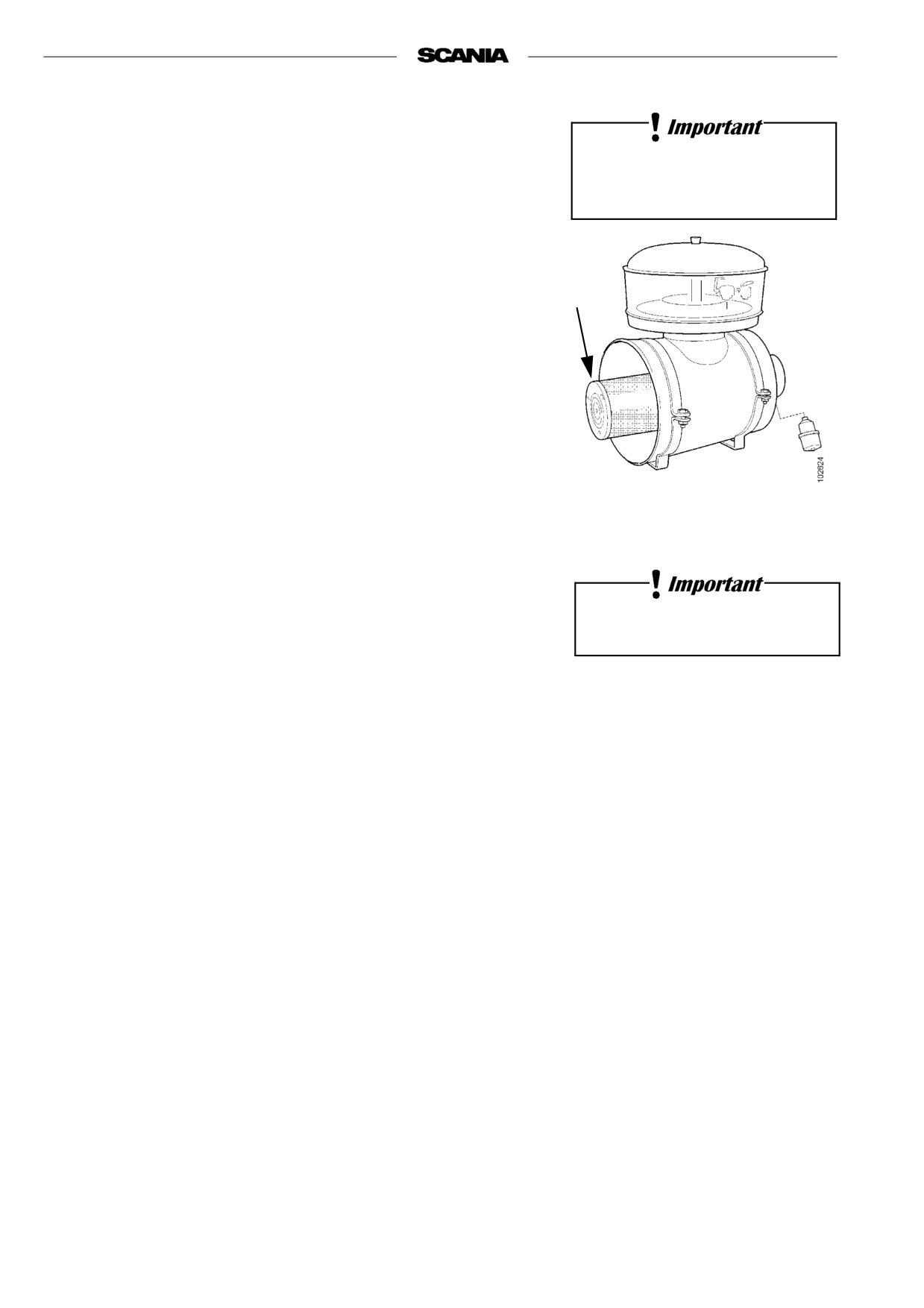
AIR CLEANER
10. Daily:
CHECKING THE VACUUM INDICATOR
If the entire red plunger of the indicator is visible, renew or clean the air filter
element, paragraph 12. This is especially important if the engine is operated
under heavy load and at high engine speed.
11. Every 200 hours:
CLEANING THE AIR CLEANER
The coarse cleaner must always
be fitted in an upright position.
COARSE CLEANER
1. Remove the cover from coarse cleaner 2.
1
2
2. Remove the conical coarse separator. Empty out the particles of dirt and
clean it.
3. Fit the coarse separator as shown in the figure and screw the cover in
place.
12. Every 1200 hours:
3
4
CLEANING OR CHANGING THE
1. Filter element
FILTER ELEMENT
2. Coarse cleaner
Note: Earlier if the vacuum indicator shows red
3. Cover
4. Vacuum sensor
Dismantling
Air cleaner with safety cartridge
1. Remove the side cover from the air cleaner.
2. Change or clean the element.
Note Cleaning the element always entails a risk of damaging it. The
Only use Scania genuine air
element can be cleaned a maximum of four times. After cleaning,
filter. Change the filter element
it has less dust separation capacity than a new element.
if it is damaged.
3. Mark the filter when it has been cleaned.
Danger of engine damage if the
Cleaning the element
filter element is damaged.
- Carefully blow the filter element clean using dry compressed air from
the inside.
Note This filter element must not be washed with water.
Never start the engine unless
1
2
3
the air filter is installed.
Danger of personal injury or
engine damage.
1. Cover
2. Filter element
3. Filter housing
42

Checking
- Insert a torch into the element and check from the outside that there are
no holes or cracks in the filter paper.
- Change the filter element if it has the slightest damage. Danger of
engine damage.
Assembly
1. Assemble the air cleaner in reverse order.
2. Reset the red plunger in the vacuum indicator by depressing the button.
Filter with a non-changeable element (unit cleaner)
Cleaning
- The filter may be cleaned a maximum of 3 times. Mark the filter after
each time it has been cleaned.
- Use a cleaning solution consisting of water mixed with approx. 1% mild
detergent.
1. Pour the cleaning solution into the element outlet at the same time as
turning the element so that the cleaning solution pours through the
element against the direction of the air flow.
2. Leave the element in the cleaning solution for 5 minutes and then take it
out so that all the cleaning solution drains away.
3. Rinse the element with ca 30 litres clean water at 30 - 40 °C. Pour the
rinsing water into the element in the same way as the cleaning solution.
4. Take out the element and allow the rinsing water to drain off.
5. Repeat the procedure until the rinsing water is clean.
6. Leave the element to dry in a warm place for a few days.
Note The element must not be dried with compressed air.
43
13. Every 2400 hours:
RENEWING THE SAFETY CARTRIDGE
Do not remove the safety
Note Not all filters are equipped with a safety cartridge. When
cartridge unnecessarily.
changing the safety cartridge, take great care to ensure that no
dirt or other impurities can get into the engine.
1. Remove the side cover from the air cleaner.
2. Remove the filter element.
1
3. Remove the safety cartridge.
4. Fit a new genuine Scania safety cartridge.
5. Renew or clean the filter element, refer to paragraph 12.
6. Assemble the air cleaner.
1. Safety cartridge
Air cleaner with safety cartridge
Never clean the safety cartridge
44

FUEL SYSTEM
Observe the utmost cleanliness
14. Daily:
when working on the fuel
system.
CHECKING THE FUEL LEVEL
Malfunctions could easily occur
- Top up with fuel if necessary.
and the injection equipment
- If the tank has been run dry, bleed the fuel system, refer to paragraph 15.
could be damaged.
15. Every 1200 hours:
RENEWING THE FUEL FILTER
Fuel tanks
- Drain any water from the fuel tanks.
Filter
The filter consists of a filter unit.
- Wash the outside of the filter and unscrew it.
- Tighten the new filter by hand.
Never use a tool for tightening. The filters can be damaged,
obstructing circulation.
- Bleed the fuel system as described below.
- Start the engine and check for leaks.
Only use Scania genuine fuel
Bleeding the fuel system
filter.
- Turn on the power so that the fuel shut-off valve opens.
- Undo the connection on fuel filter outlet 1 (upwards).
- Pump hand pump 3 until fuel without air bubbles flows out of the
opened connection.
Always collect fuel in a suitable
container to avoid spillage when
- Tighten the connection on the filter.
bleeding system or renewing
- Undo the overflow valve 2 at the fuel shut-off valve outlet.
components.
- Pump with the hand pump until the fuel coming out of the open
overflow valve is free of air bubbles.
2
1
- Tighten the overflow valve and pump the hand pump an additional 10
3
strokes.
If the engine fails to start after bleeding
- Open the overflow valve again and pump the hand pump until fuel
without air bubbles flows out.
- Close the overflow valve firmly and start the engine.
45

16. Every 2400 hours:
1. Threaded
CHECKING THE INJECTORS
socket nut
2. O-ring
Injectors should be inspected by trained personnel with access to the
necessary equipment. Inspection should be carried out at least once a year or
3. O-ring
every 2400 hours.
4. Stop ring
Removal
5. Guide pin
6. Seal
1. Clean around the injectors and connections, including clamps and
brackets.
2. Detach the delivery pipe bundle and leak-off fuel lines.
3. Unscrew the injector.
4. Fit protective plugs on the injector and delivery pipe.
5. Lift up the seal from the bottom of the injector seat if it does not come
out together with the injector.
The delivery pipes must
6. Fit a core plug in the injector seat in the cylinder head.
not be bent.
7. Clean the injectors and check/adjust in a nozzle tester.
All clamps must be refitted.
Correct opening pressure, see Technical data, page 58.
Fitting
Always wear gloves and eye
1. Check that there is no old seal in place and fit a new seal in the bottom
protection when testing
of the injector seat.
injectors.
2. Fit a new O-ring in the socket nut and a new seal under the socket nut.
Fuel escaping under high
3. Fit the injector.
pressure can penetrate body
tissue and cause serious injury.
4. Tighten the socket nut to 70 Nm (7.0 kpm).
5. Fit the delivery pipe and tighten the union nuts to 20 Nm (2.0 kpm). Fit
clamps and brackets.
Important Take care to fit the delivery pipe without tension and make sure
that the cone on it is correctly positioned in the connection.
6. Fit the leak-off fuel line. Tighten the bolts to 11 Nm (1.1 kpm).
1. Delivery pipe
2. Union nut
3. Washer
4. Cone
5. Connection on injector or
injection pump
46
ELECTRICAL SYSTEM
17. Every 200 hours:
Do not let open flame or sparks
CHECKING THE ELECTROLYTE
come near the batteries.
LEVEL IN BATTERIES
When batteries are charged,
they emit highly flammable
1. Unscrew the plugs and check the electrolyte level in all cells.
fumes that can explode.
2. Top up with distilled water until the level is 10-15 mm above the plates.
18. Every 200 hours:
CHECKING THE STATE OF CHARGE IN
BATTERIES
Note Every 200 hours applies to generator sets and the like. Other
installations every 1200 hours.
Wear gloves and eye protection
- Check the density with an acid tester.
when charging and
In a fully-charged battery it should be:
handling batteries.
1.280 at +20°C
Batteries contain a highly
corrosive acid.
1.294 at 0°
1.308 at -20°C
- If the density is below 1.20, the battery must be charged. A discharged
battery freezes at -5°C.
Do not rapid-charge the batteries. This will damage the battery in the
long run.
19. Every 200 hours:
Do not connect the cables to the
wrong terminals.
CLEANING THE BATTERIES
This could cause serious
damage to the electrical system.
Note Every 200 hours applies to generator sets and the like. Other
installations every 1200 hours.
If the terminals are
shortcircuited, sparks
1. Clean batteries, cables and cable terminals.
will be generated.
2. Check that all cable terminals are firmly tightened.
3. Grease battery terminal posts and cable terminals with vaseline.
47