Scania DI9 55 - DI9 59. Marine engine. Operator’s manual - part 3
8. Every 2400 hours:
CHECKING THE COOLANT
Coolant should be checked as follows:
Coolant composition:
a) Check the appearance of the coolant.
If there is a danger of freezing:
b) Coolant with glycol: Check the glycol content.
minimum 30% glycol by
c) Coolant with Scania Anti-corrosive:
volume
Check the anti-corrosive content.
maximum 60% glycol by
volume
The coolant composition is also described under
If there is no danger of freezing:
"Starting and running".
7-12% by volume
Scania Anti-corrosive
a)
Checking the appearance of the coolant
- Fill a receptacle with a little coolant and check that it is clean and clear.
- If the coolant is contaminated or cloudy, consider changing it.
- Water added to the coolant should be clean and free from dirt of any
kind.
- Use drinking water with a pH of 6 - 9.
b)
Checking the glycol content
If there is a danger of freezing, use only glycol as an anti-corrosive in the
coolant.
Ethylene glycol is highly
- Cooling systems with glycol should contain at least 30% glycol by
volume to provide acceptable protection against corrosion.
dangerous if ingested and can
prove fatal.
- A content of 30% glycol by volume protects against freezing down to
-16°C. If further protection is needed, refer to the table on the next page
Avoid skin contact with glycol.
for calculating the required amount of glycol.
We recommend only nitrite-free anti-freeze glycol with the following
supplier designations: BASF G48 or BASF D542
- Always top up the anti-freeze if its glycol content drops below 30% by
volume. A glycol content above 60% by volume will not provide greater
The coolant should be ready
protection against freezing.
mixed when it is poured into the
cooling system.
- The table shows the temperature at which ice starts to form. The engine
will freeze and fracture at appreciably lower temperatures, see diagram.
Never top up with only water or
only glycol.
- Ice forming in the coolant often causes malfunctioning without any risk
of damage. The engine should not be subjected to heavy loads when ice
starts to form.
Note Change the coolant when cleaning the cooling system: Every 4800
hours or minimum every 5 years.
The recommended glycol must
Important If a coolant filter is used in the cooling system, it must not con-
not be mixed with glycol having
tain an inhibitor.
nitrite-based anti-corrosive.
Risk for build up of sludge and
reduced cooling capacity.
32
2001-05:1

% glycol by volume
Properties of glycol at low temperatures:
- Example with 30% glycol by volume
- Ice slush starts to form at -16°C.
- There is risk for malfunctions at -30°C
- No risk of damage by freezing with a minimum
content of 30% glycol by volume
Curve A: Ice build up starts (slush)
Curve B: Temperature at which damage due to
freezing can occur
1. Safe range
2. Malfunctions may occur (ice slush)
3. Risk of damage by freezing
A
% glycol by
15
20
25
30
35
40
45
50
60
Cooling
volume
system
Ice slush starts
capacity, dm3
-6
-9
-12
-16
-22
-27
-36
-46
-55
to form at °C
5
6
8
9
11
12
14
15
18
30
6
8
10
12
14
16
18
20
24
40
8
10
13
15
18
20
23
25
30
50
9
12
15
18
21
24
27
30
36
60
11
14
18
21
25
28
32
35
42
70
12
16
20
24
28
32
36
40
48
80
14
18
23
27
32
36
41
45
54
90
15
20
25
30
35
40
45
50
60
100
Glycol dm3
17
22
28
33
39
44
50
55
66
110
(litres)
18
24
30
36
42
48
54
60
72
120
20
26
33
39
46
52
59
65
78
130
21
28
35
42
49
56
63
70
84
140
23
30
38
45
53
60
68
75
90
150
24
32
40
48
56
64
72
80
96
160
26
34
43
51
60
68
77
85
102
170
27
36
45
54
63
72
81
90
108
180
29
38
48
57
67
76
86
95
114
190
30
40
50
60
70
80
90
100
120
200
A= Area to be avoided. Only for calculating glycol mix.
Coolant freezing temperature when ice starts to form at different glycol mixes
2001-05:1
33

c)
Checking protection against corrosion
There must always be sufficient corrosive inhibitor in the coolant to protect
the cooling system against corrosion.
Corrosion inhibitor, if
If there is no danger of freezing, only Scania Anti-corrosive should be used.
swallowed can be fatal.
The inhibitor in Scania Anti-corrosive is nitrite-free.
Avoid contact with the skin.
The correct proportion of anti-corrosive is 7-12% by volume.
- Topping up with 1.0% Scania Anti-corrosive by volume should be done
after every 2400 hours of operation.
- Never top up with only water or only anti-corrosive!
Mixing corrosion inhibitor with
Fluid losses must always be replaced with premixed coolant:
glycol or adding too much
water + 10% by volume of Scania Anti-corrosive.
corrosion inhibitor may cause
Note The coolant should be changed when the cooling system is
deposits and reduced cooling
cleaned: every 4800 hours or minimum every 5 years.
capacity.
If a coolant filter has been fitted
it must not contain inhibitor.
Changing the coolant
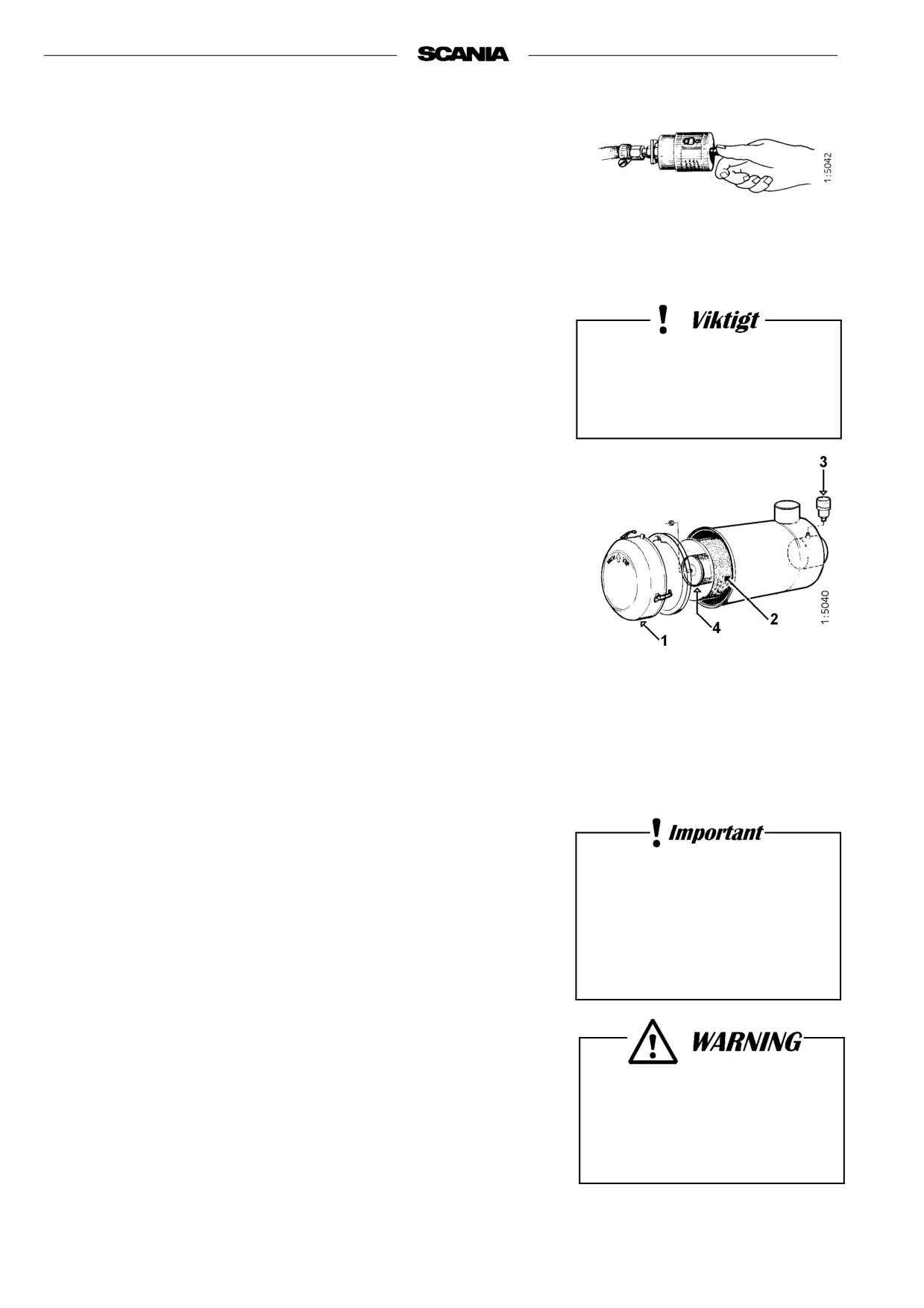
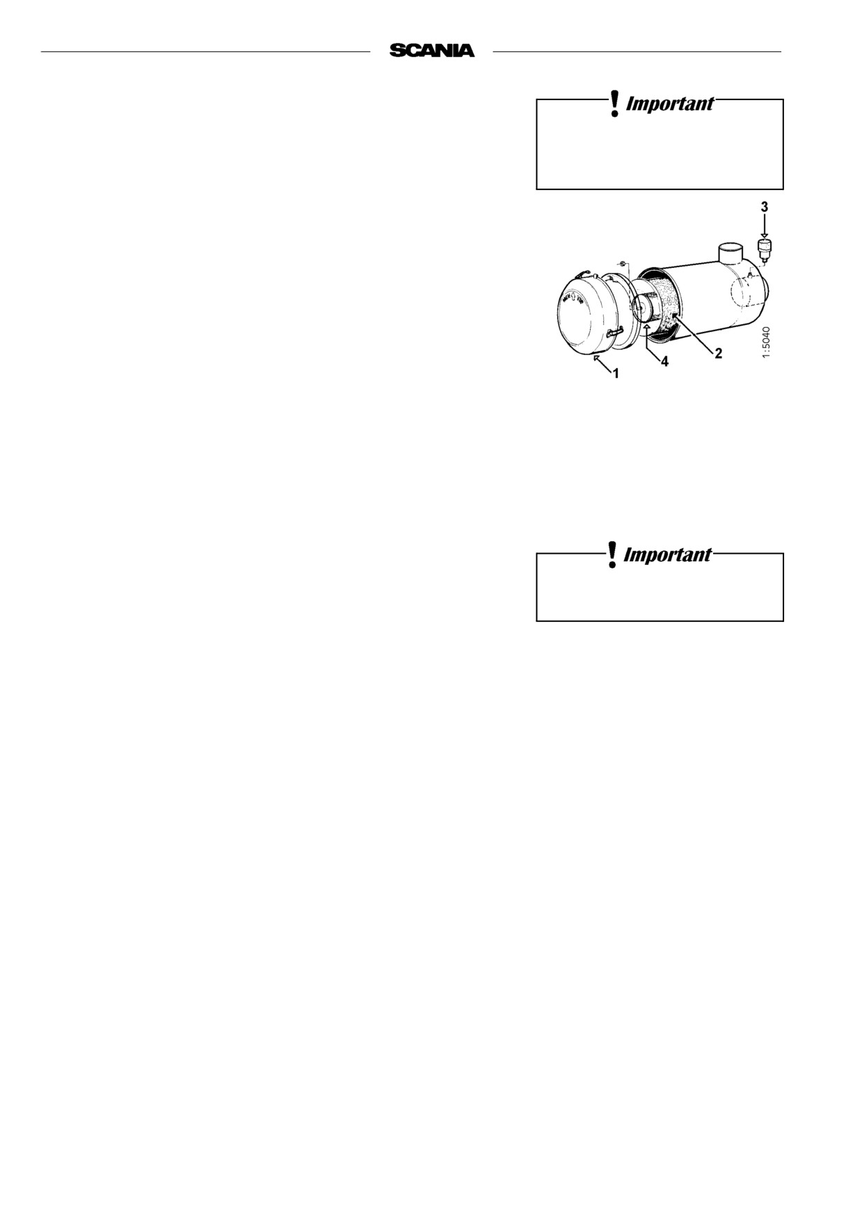
1. Remove the filler cap from the expansion tank.
2. The coolant is drained at two points as illustrated:
- from the underside of the heat exchanger by removing two plugs.
- through a valve in the unit.
3. Close the valve and refit the plugs.
4. Top up with coolant through the expansion tank filler hole.
Mix coolant as described on page 32.
Always collect fluid in a suitable
container to avoid spillage when
changing coolant.
Dispose of used coolant through
an authorized waste disposal
contractor.
34
2001-05:1

9. Every 4800 hours:
CLEANING THE COOLING SYSTEM
Note If necessary, the cooling system should be cleaned more often.
External cleaning
The cooling system must never
Heat exchanger
be cleaned with caustic soda.
1. Drain the coolant from the engine, see “Changing coolant”.
There is a risk of damage to
2. Drain the seawater circuit.
aluminium parts.
3. Detach the heat exchanger hose and pipe connections.
4. Start by removing the charge air cooler and then dismantle the heat
exchanger as illustrated.
5. Clean the outside of the element. Use a paraffin-based engine cleaner.
6. Any deposit on the inside of the pipes is removed mechanically using a
round file.
7. Change the O-rings and assemble the heat exchanger
See “Charge air cooler”.
8. Refit hose and pipe connections.
9. Fill the system with coolant as described on page 32.
1. Cover
2. O-ring
3. Flange
4. Heat exchanger
5. Heat exchanger ele-
ment
6. Cover
2001-05:1
35

Charge air cooler
1. Drain the coolant from the engine, see "Changing the coolant".
2. Drain the seawater circuit.
3. Detach the connections to the turbo and the intake manifold.
4. Detach the water connection from the charge air cooler’s outlet.
5. Remove the complete charge air cooler and dismantle it as illustrated.
6. Clean the outside of the element. Use a paraffin-based engine cleaner.
7. Any deposit on the inside of the pipes is removed mechanically using a
round file.
The cooling system must never
8. Change the O-rings and assemble the charge air cooler.
be cleaned with caustic soda.
9. Refit the charge air cooler to the heat exchanger.
There is a risk of damage to
10. Refit the hose connections to the turbo and intake manifold and the con-
aluminium parts.
nection to the charge air cooler cover.
11. Fill the system with coolant as described on page 32.
12. Connect the intake manifold from the turbo.
1. Spacer
2. O-ring
3. Flange
4. Charge air cooler hou-
sing
5. Charge air element
6. Cover
7. Heat exchanger
36
2001-05:1
Internal cleaning
Removing oils and greases
- If possible, run the engine until it has reached the operating
temperature and then drain the cooling system.
- Remove the thermostats.
- Fill the system with clean, hot water mixed with liquid dishwasher
detergent designed for household use.
Handling cleaning agents for
Concentration 1% (0.1/10 l).
the cooling system:
- Run the engine until it has reached operating temperature for about
Read the warning label on the
20-30 minutes. Do not forget the cab heating system (if fitted).
container.
- Drain the cooling system.
- Fill the system again using clean, hot water and run the engine for
about 20-30 minutes.
- Drain the water from the system.
- Refit the thermostats.
- Top up the system with coolant according to the specification on page
32.
Removing deposits
Always collect fluid in a suitable
- If possible, run the engine until it has reached the operating temperature
container to avoid spillage when
and then drain the cooling system.
draining coolant.
- Remove the thermostats.
Dispose of used coolant through
an authorized waste disposal
- Fill the system with clean, hot water mixed with one of the
commercially available radiator cleaners based on sulphamic acid and
contractor.
containing dispersing agents. Follow the manufacturer’s instructions for
mixing proportions and cleaning times.
- Run the engine for the specified time and then drain the cooling system.
- Refill the system with hot water and run the engine for about 20-30
minutes.
- Drain the water from the system.
- Refit the thermostats.
- Top up the system with coolant according to the specification on page
32.
2001-05:1
37
AIR CLEANER
10. Daily:
READING THE VACUUM INDICATOR
If the entire red plunger of the indicator is visible, renew or clean the air filter
element, paragraph 12. This is especially important if the engine is operated
under heavy load and at high engine speed.
11. Every 200 hours:
The coarse cleaner should be
CLEANING THE AIR CLEANER
fitted with the marking ”TOP”
facing up.
COARSE CLEANER
1. Detach the eccentric catch and remove the coarse cleaner.
2. Remove the plastic cover from the coarse cleaner and clean the parts.
3. Check that the plastic cover is intact and that it makes a seal against the
air cleaner housing during assembly.
4. Assemble the air cleaner
12. Every 1200 hours:
CLEANING OR CHANGING THE
1. Pre-filter with cover
2. Filter insert
FILTER ELEMENT
3. Low pressure indicator
Note Earlier if the low pressure indicator shows red.
4. Safety cartridge
Disassembly
1. Remove and clean the coarse cleaner, see point 11.
2. Undo the nut securing the filter element and remove it.
Only use Scania genuine air
3. Change or clean the element.
filter. Change the filter element
Note Cleaning the element always entails a risk of damaging it. The
if it is damaged.
element can only be cleaned a maximum of four times. After
cleaning, it has poorer dust capacity than a new element.
Danger of engine damage if the
filter element is damaged.
4. Mark the filter when it has been cleaned.
Cleaning the element
- Carefully blow the filter element clean using dry compressed air from
the inside.
Never start the engine unless
Note This filter element must not be washed with water.
the air filter is installed.
Danger of personal injury or
engine damage.
38
2001-05:1
Checking
- Insert a flashlamp into the insert and check from the outside that there
are no holes or cracks in the filter paper.
- Change the filter insert if there is any damage at all. Danger of engine
damage.
Assembly
1. Assemble the air cleaner in reverse order.
2. Reset the red plunger in the low pressure indicator by pressing in the
button
Filter with a non-changeable element (unit cleaner)
Cleaning
- The filter may be cleaned a maximum of 3 times. Mark the filter after
each time it has been cleaned.
- Use a cleaning solution consisting of water mixed with approx. 1% mild
detergent.
1. Pour the cleaning solution into the element outlet at the same time as
turning the element so that the cleaning solution pours through the
element against the direction of the air flow.
2. Leave the element in the cleaning solution for 5 minutes and then take it
out so that all the cleaning solution drains away.
3. Rinse the element with ca 30 litres clean water at 30 - 40 °C. Pour the
rinsing water into the element in the same way as the cleaning solution.
4. Take out the element and allow the rinsing water to drain off.
5. Repeat the procedure until the rinsing water is clean.
6. Leave the element to dry in a warm place for a few days.
Note The element must not be dried with compressed air.
2001-05:1
39
13. Every 2400 hours:
CHANGING SAFETY CARTRIDGE
Do not remove the safety
cartridge unnecessarily.
1. Remove and clean the coarse cleaner, see point 11.
2. Undo the nut securing the filter insert and remove it.
3. Change or clean the filter insert, see point 12.
4. Undo the nut securing the safety cartridge and remove it.
5. Fit a new Scania genuine safety cartridge.
6. Assemble the air cleaner.
1. Pre-filter with cover
2. Filter insert
3. Low pressure indicator
4. Safety cartridge
Air cleaner with pre-filter
Never clean the safety cartridge
40
2001-05:1
FUEL SYSTEM
Be extremely careful with
cleanliness when working on
14. Daily:
the fuel system.
CHECKING FUEL LEVEL
Malfunctions
can easily arise and the
- Top up fuel if necessary.
injection equipment
- If the tank is run dry, bleed the fuel system, see point 15.
can be damaged.
15. Every 1200 hours:
CHANGING THE FUEL FILTER
Fuel tanks
- Drain any water from the fuel tanks.
Main filter
The filter consists of a filter unit.
- Wash the outside of the filter and unscrew it.
- Fit the new filter and tighten it by hand.
Never use a tool for tightening. The filters can be damaged,
obstructing circulation.
- Bleed the fuel system as described below.
Only use Scania genuine fuel
- Start the engine and check for leaks.
filter.
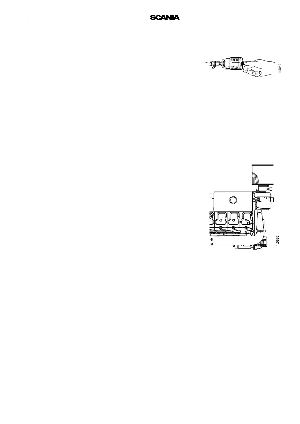
Bleeding the fuel system
- Turn on the power so that the fuel shut-off valve opens.
- Undo the connection on fuel filter outlet 1 (upwards).
Always collect fuel in a suitable
- Pump hand pump 3 until fuel without air bubbles flows out of the
opened connection.
container to avoid spillage when
bleeding system or renewing
- Tighten the connection on the filter.
components.
- Undo the overflow valve 2 at the fuel shut-off valve outlet.
- Pump with the hand pump until the fuel coming out of the open
3
2
1
overflow valve is free of air bubbles.
- Tighten the overflow valve and pump the hand pump an additional
10 strokes.
If the engine fails to start after bleeding
- Open the overflow valve again and pump the hand pump until fuel
without air bubbles flows out.
- Close the overflow valve firmly and start the engine.
2001-05:1
41
16. Every 2400 hours:
CHECKING INJECTORS
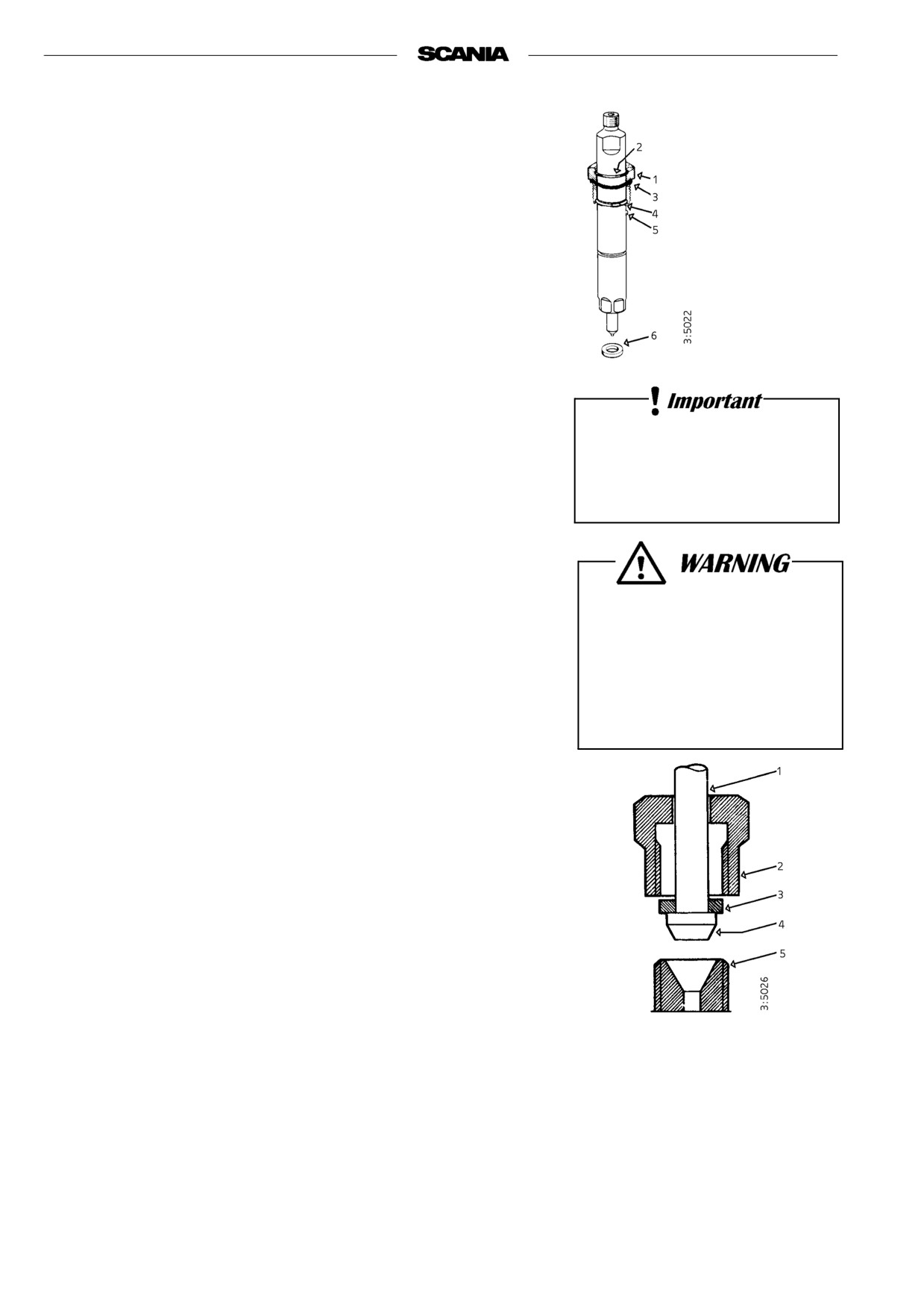
1. Socket nut
2. O-ring
Injectors should be inspected by trained personnel with access to the neces-
3. O-ring
sary equipment. Inspection should be carried out at least once a year or every
2400 hours.
4. Stop ring
5. Guide pin
Removal
6. Seal
1. Clean round the injectors and connections, including clamps and
brackets.
2. Detach the delivery pipe bundle and leak-off fuel lines.
3. Unscrew the injector.
4. Fit protective plugs on the injector and delivery pipe.
5. Lift up the seal from the bottom of the injector seat if it does not come
out together with the injector.
The delivery pipes must
6. Fit a core plug in the injector seat in the cylinder head.
not be bent.
7. Clean the injectors and check/adjust in a nozzle tester.
All clamps must be refitted.
Correct opening pressure, see Technical data, page 54.
Fitting
1. Check that there is no old seal in place and fit a new seal in the bottom
of the injector seat.
Always wear gloves and eye
2. Fit a new O-ring in the threaded socket nut and a new seal under the
protection when testing
socket nut.
injectors.
3. Fit the injector.
Fuel escaping under high
pressure can penetrate body
4. Tighten the socket nut to 70 Nm (7.0 kpm).
tissue and cause serious injury.
5. Fit the delivery pipe and tighten the cap nut to 20 Nm (2.0 kpm). Fit
clamps and brackets.
Important Take care to fit the delivery pipe without tension and make sure
that the cone on it is correctly positioned in the connection.
6. Fit the leak-off fuel line. Tighten the bolts to 11 Nm (1.1 kpm).
1. Delivery pipes
2. Cap nut
3. Washer
4. Cone
5. Connector on injector or
injection pump
Delivery pipe connection
42
2001-05:1
ELECTRICAL SYSTEM
17. Every 200 hours:
Do not let open flame or sparks
CHECKING THE
come near the batteries.
ELECTROLYTE LEVEL IN BATTERIES
When batteries are charged,
they emit highly flammable
1. Unscrew the plugs and check the electrolyte level in all cells.
fumes that can explode.
2. Top up with distilled water until the level is 10-15 mm above the plates.
18. Every 1200 hours:
CHECKING THE STATE OF CHARGE
IN BATTERIES
- Check the density with an acid tester.
In a fully-charged battery it should be:
Wear gloves and eye protection
1.280 at +20 °C
when charging and
1.294 at 0 °C
handling batteries.
Batteries contain a highly
1.308 at -20 °C
corrosive acid.
- If the density is below 1.20, the battery must be charged.
A discharged battery freezes at -5 °C.
Do not boost charge the batteries. This will damage the battery in the
long run.
19. Every 1200 hours:
CLEANING BATTERIES
Do not connect the cables to the
1. Clean batteries, cables and cable terminals.
wrong terminals.
2. Check that all cable terminals are firmly tightened.
This could cause serious
damage to the electrical system.
3. Grease battery terminal posts and cable terminals with vaseline.
If the terminals are
shortcircuited, sparks
will be generated.
2001-05:1
43

20. Every 1200 hours:
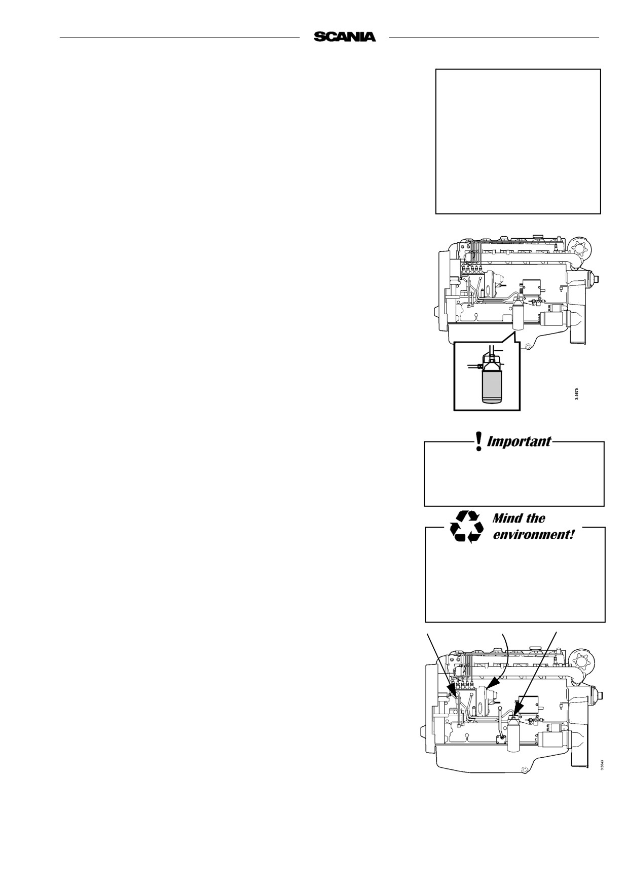
CHECKING THE COOLANT LEVEL
MONITOR
(optional equipment)
Note Check the coolant level monitor when the engine is cold.
1. Loosen the coolant level monitor cable clamps towards the cable
cluster and disconnect the connector.
2. Put a container under the heat exchanger and unscrew the monitor.
Immediately insert a threaded plug M18x1.5 in the hole for the
monitor. Avoid contact with the skin when handling coolant.
3. Connect the monitor connector and put the control switch in the "ON"
position.
4. Check that the warning lamp remains on and that the buzzer sounds
(if fitted).
5. Lower the monitor into a metal container (steel) with liquid. It is
important that the monitor body is in contact with the metal.
6. After approximately 2 seconds the warning lamp should go out.
7. Remove the monitor from the liquid. After approximately 7 seconds
the warning lamp will come on and the buzzer sound (if fitted).
8. Disconnect the monitor connector and screw on the monitor again.
9. Clamp the monitor cable as before and connect the connector.
10. Top up the system with coolant according to the specification on
page 32.
44
2001-05:1
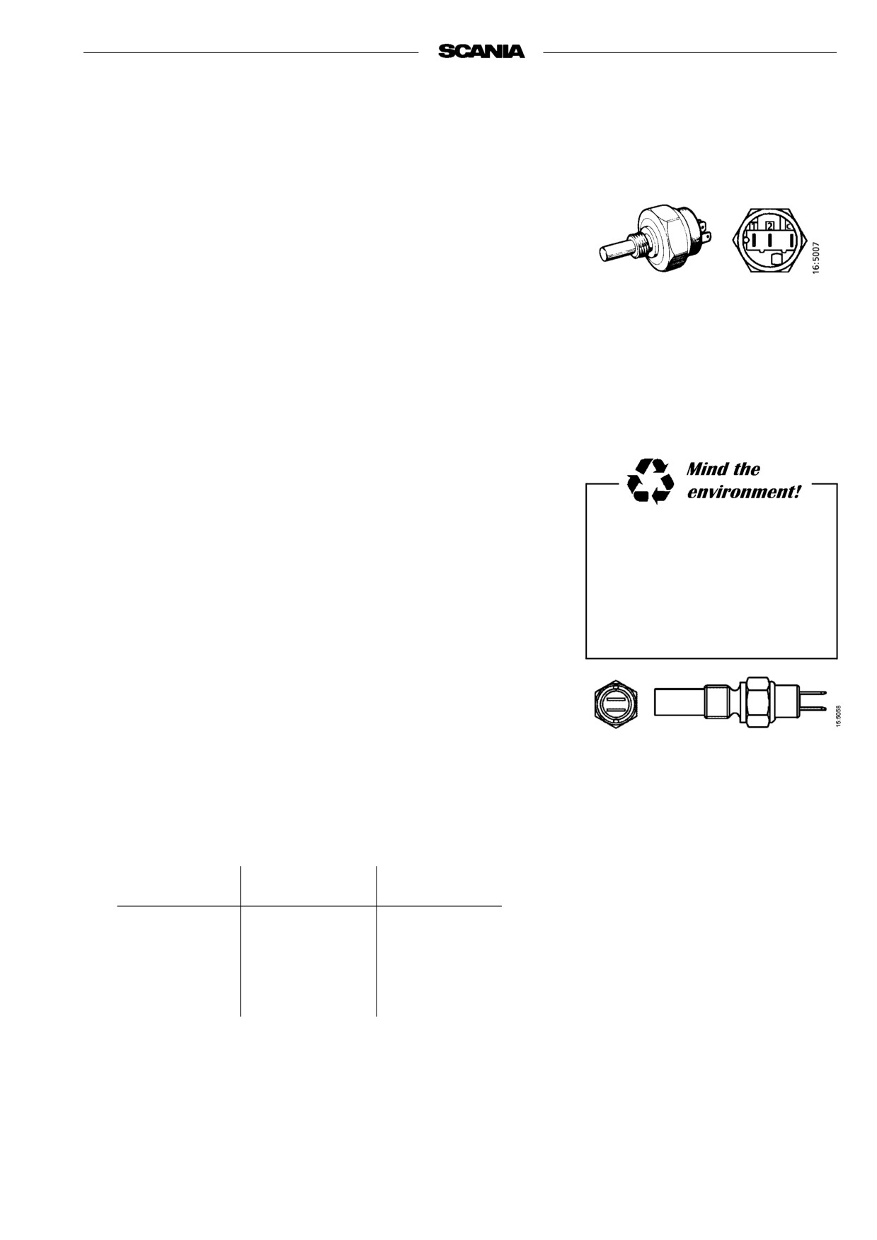
21. Every 1200 hours:
CHECKING THE
TEMPERATURE MONITOR
1. Drain the coolant, allowing the temperature monitor to be removed.
2. Remove the temperature monitor cable(s).
3. Unscrew the monitor.
C = Common connection
4. Refit the cable(s) on the monitor.
1 = Connection C -1 closes at
5. Submerge the monitor sensor body in water. Heat the water slowly
the stamped temperature
(about 1° per minute) with for example an immersion heater.
2 = Connection C -2 opens at the
6. Set the control switch to "ON". Use a thermometer to check that the
stamped temperature
warning lamp comes on or that an alarm is initiated at the correct
temperature.
2-pole temperature monitor
The correct temperature is stamped on the hexagonal part of the
monitor.
The temperature tolerance is ± 3°.
Always use a suitable container
to avoid spillage when
draining coolant.
Dispose of used coolant through
an authorized waste disposal
CHECKING THE TEMPERATURE
contractor.
SENSOR
1. Drain the coolant, allowing the temperature sensor to be removed.
2. Remove the temperature sensor cable(s).
3. Unscrew the sensor.
4. Connect an ohmmeter to the temperature sensor.
5. Submerge the sensor body in water. Heat the water slowly
2-pole temperature sensor
(about 1° per minute) with for example an immersion heater.
6. Check the resistance at the temperatures given below.
7. The sensor should give the following readings:
At temp. °C
Resistance Ω
Tolerance °C
60
134 ± 13.5
±4
90
51.2 ± 4.3
±3
100
38.5 ± 3
±3
2001-05:1
45
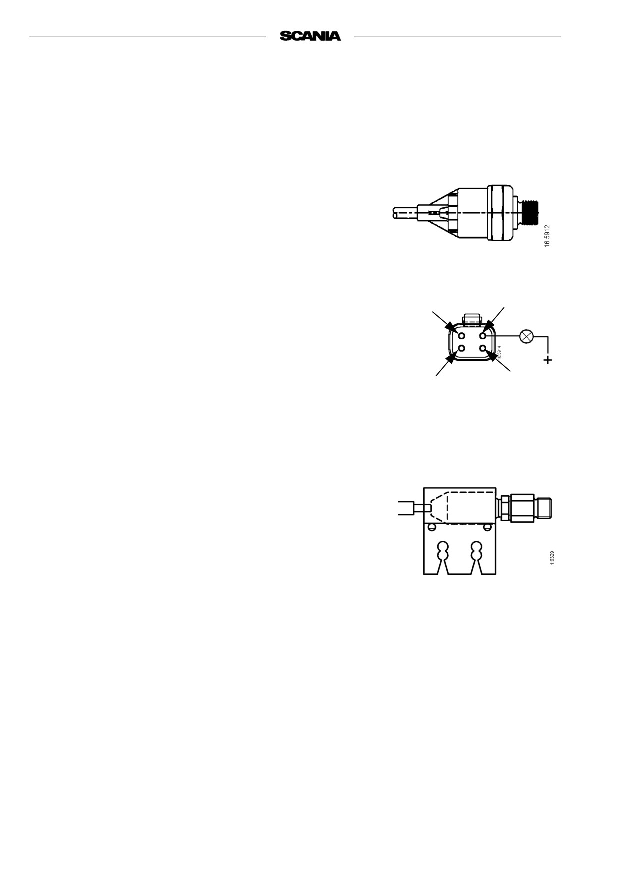
22. Every 1,200 hours:
CHECKING THE OIL PRESSURE
SENSOR/MONITOR
Sensor function
Measure the sensor output voltage (pin 3) at different oil pressures. The
sensor output voltage shall be as follows:
0.85-1.15 bar
=
2.45 volt
1.80-2.20 bar
=
3.70 volt
2.75-3.25 bar
=
4.50 volt
3.79-4.20 bar
=
5.20 volt
4.55-5.45 bar
=
5.70 volt
5.40-6.6 bar
=
6.10 volt
The tolerances apply at +30°C - 110°C. At lower temperatures the tolerance
range is wider, e.g. 0°C = x 1.4.
4
1
Monitor function
Connect a test lamp to the oil pressure monitor, pin 4 (- ground), and check
that the monitor switches on at the correct pressure when the engine is started
and stopped. The monitor shall switch on at 0.7 ± 0.15 bar when the engine is
3
stopped.
2
Important The sensor/monitor must be supplied with voltage during the
measurement. Maximum 4 W load from a test lamp.
CHECKING THE OIL PRESSURE
MONITOR FOR DEC 2
Connect an ohmmeter or a test lamp to the oil pressure monitor and check
that the monitor switches off/on at the correct pressure when the engine is
started and stopped. The monitor shall switch off at 1.1 ± 0.15 bar when the
engine is started and switch on at 0.7 ± 0.15 bar when the engine is stopped.
46
2001-05:1

CHANGING THE BATTERY
Removal
Do not connect the cables to the
wrong terminals.
1. Disconnect the negative cable (-) from the battery (cable connected to
earth).
This could cause serious
damage to the electrical system.
2. Disconnect the positive cable (+) from the battery (cable connected to
starter motor).
If the terminals are short-
circuited, sparks will be
Fitting
generated.
1. Connect the positive cable (+) to the battery (cable connected to starter
motor).
2. Connect the negative cable (-) to the battery (cable connected to earth).
Dispose of used batteries
through an authorized waste
disposal contractor.
MISCELLANEOUS
23. Every 1200 hours:
CHECKING THE DRIVE BELT
Replace the drive belt (1) (poly V-belt) if worn or damaged.
2
Also check that the automatic belt tensioner (2) is working and keeps the
drive belt correctly tensioned.
1
2001-05:1
47