Scania DI9 55 - DI9 59. Marine engine. Operator’s manual - part 2
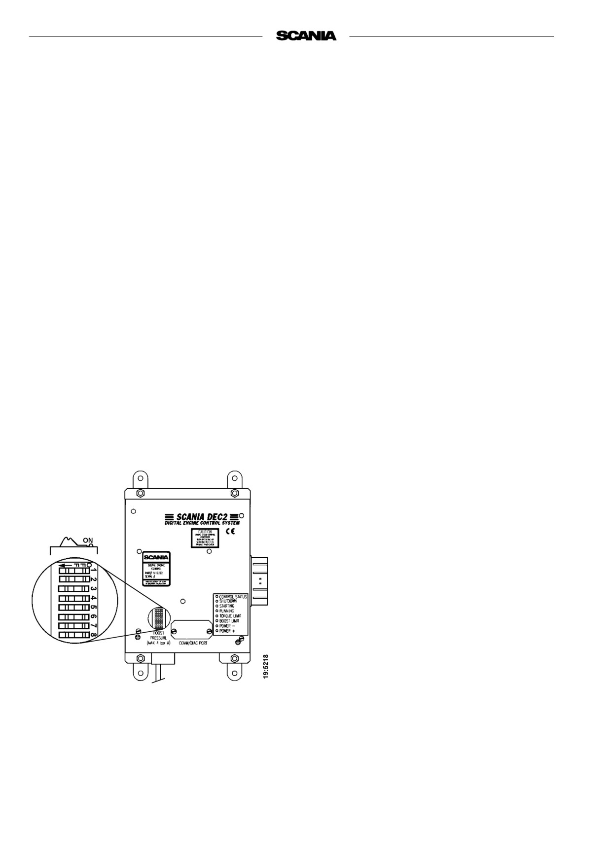
Changing functions using the DIP
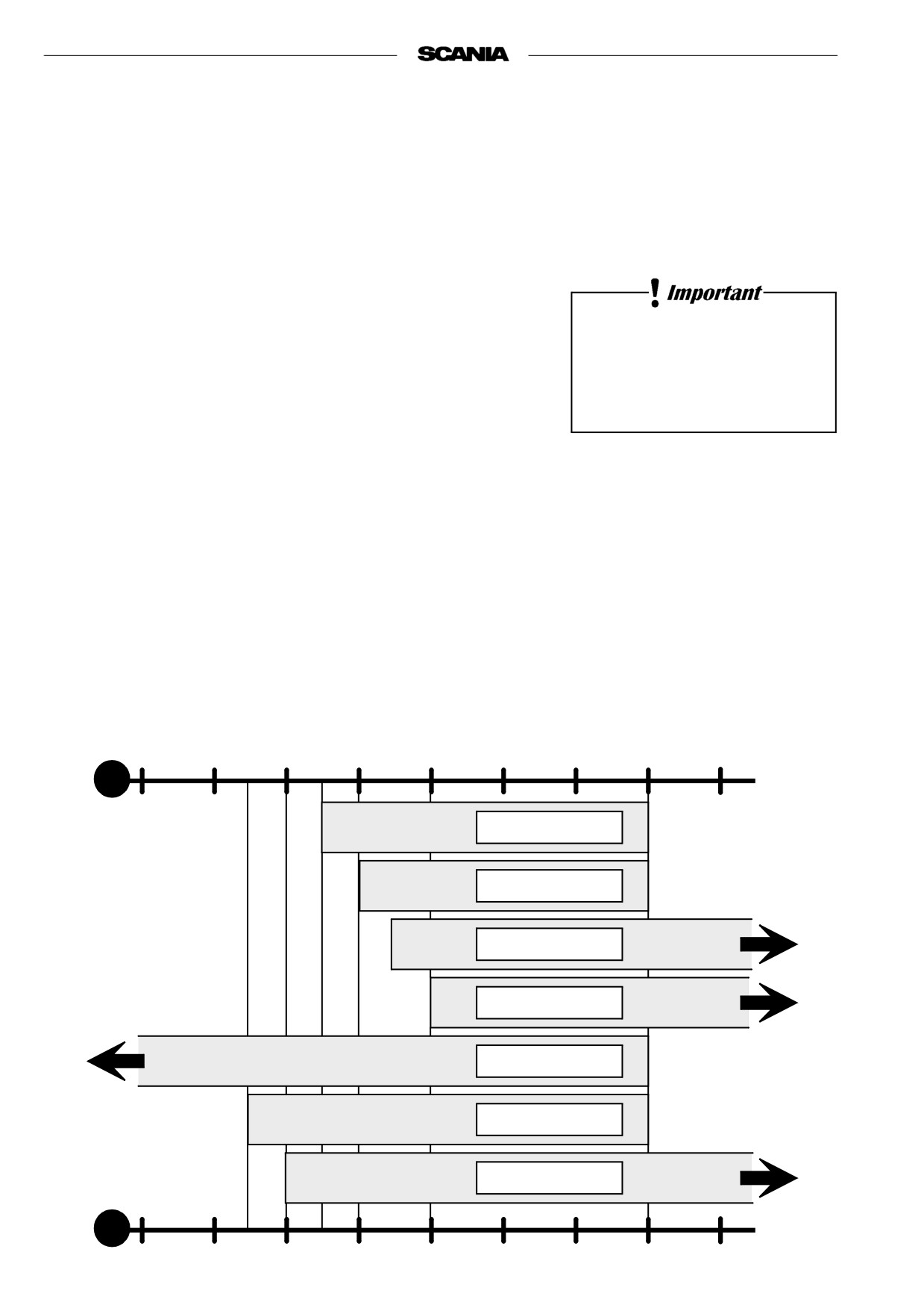
Readout of fault codes
switches in the control unit
Note If the engine has stopped or lost power but
There are 8 DIP switches in the control unit under the
the main indicator lamp is out and neither
round black rubber cover.
POWER- nor SHUTDOWN are on, the
fault is outside the control unit detection
These switches shall be in the ON position to obtain
range. Probable causes: fuel shortage,
normal functions according to the operating program.
temporary overload, mechanical fault.
However, for single-speed engines, the normal
position of DIP switches 6, 7, and 8 may also be OFF
-
Activate the lamp test/fault code switch. In
Scania electrical equipment the main indicator
Shutdown at threshold values for low oil pressure and
lamp is located in this switch on the main supply
high coolant temperature can be selected by setting
box.
DIP switch 4 to OFF
-
All LEDs will then come on for 2 seconds to
With DIP switch 4 in position ON, Power- indication
indicate that they are intact and in working order.
is obtained for these threshold values. Engine output
This also applies to the main indicator lamp in the
reduction (LOP) can be selected to prevent damage to
main supply box and the instrument panel. Make
the engine. Changes to the program must only be
a note of any LED that is defective.
performed by authorized personnel.
-
All LEDs will then be out for approximately 4
Note
Do not operate the engine with a Power-
seconds.
indication except for in emergencies.
-
Following this, a fault code will be indicated on
one of the LEDs for 2 seconds. Note which LED
it is.
-
The control unit then resumes the operating mode
automatically.
-
After having made a note of the fault code, reset
the lamp test/fault code switch and reset the
control unit by turning off its power supply
momentarily.
-
The most probable cause of the fault can then be
found in the trouble shooting schedule on the next
page.
-
When the fault or faults have been rectified the
engine can be restarted.
-
If the control system continues to indicate a fault
by way of the main indicator lamp, further faults
may have been recorded. The fault code readout
must then be repeated as per above since the
system can only display one fault code at a time.
-
The fault(s) will be stored in a special memory in
the control unit along with information about the
operating time when it(they) occurred. Stored
faults can be accessed and erased by authorised
service personnel.
DIP switches are shown in the ON position
16
2001-05:1

READOUT OF FAULT CODES
LED INDICATION WHEN THE LAMP TEST/FAULT CODE SWITCH IS ACTIVATED
Probable cause
Action
Send in the control unit for repair as soon as
✹
DEC2 has detected an internal fault in the control unit.
possible.
The engine temperature has reached the threshold level
Check the cooling system. Check the temperature
✹
or the temperature sensor is inoperative.
sensor and cable routing.
The engine has reached the overrevving limit or the
Check the wiring and connector.
✹
engine speed sensor is inoperative.
Renew the engine speed sensor.
✹
Control rack position sensor inoperative.
Check connectors and cables to governor.
The intake air temperature has reached the threshold
Check the intake system. Check the temperature
✹
level or the charge air temperature sensor is inoperative.
sensor and cable routing.
DEC2 detects no charge air pressure.
Check the charge air pressure hose. Send in the
✹
The charge air pressure sensor is inoperative.
control unit for repair if the connection is damaged.
Engine speed potentiometer or the idling safety switch
Check the cable routing, connectors and cables.
✹
is inoperative.
The oil pressure has dropped to the threshold level or
Check oil level, connector and cable.
✹
the oil pressure monitor is inoperative.
Renew the oil pressure monitor.
✹=LED on
STARTING AND RUNNING
AT FIRST START
Coolant composition:
When the engine is started for the first time, follow the maintenance points
listed under "First start" in the maintenance schedule, see page 25.
If there is a danger of freezing:
Since the points are important for satisfactory operation of the engine right
minimum 30% glycol by volume
from the outset, they are also listed below.
maximum 60 % glycol by volume
1. Checking the oil level (see page 27).
8. Checking the coolant (see page 32).
If there is no danger of freezing:
The coolant should contain corrosion inhibitor to protect the cooling
7-12% by volume
system from corrosion.
Scania Anti-corrosive
If there is a danger of freezing:
(no glycol)
- Only anti-freeze glycol should be used in the coolant as protection
against corrosion. We recommend only nitrite-free anti-freeze glycol
with the following supplier designations:
BASF G48 or BASF D542
- The concentration of glycol should be 30 - 60% by volume depending
Ethylene glycol and corrosion
on the ambient temperature. A content of 30 % by volume provides
inhibitor, if swallowed can be
protection down to -16 °C. See page 32.
fatal.
- Never top up with only water or only glycol. Fluid losses must always
Avoid contact with the skin.
be replaced with pre-mixed coolant having the same glycol
concentration as that in the engine. If the glycol content drops, both
anti-freeze protection and protection against corrosion are impaired.
Note A glycol concentration below 30% by volume will not provide
sufficient protection against corrosion. Glycol concentrations
The recommended glycol must
higher than 60% do not improve anti-freeze protection and have
not be mixed with glycol having
a negative effect on engine cooling capacity.
nitrite-based anti-corrosive.
If there is no danger of freezing:
- Only Scania Anti-corrosive should be used in the coolant as protection
against corrosion. The correct concentration of anti-corrosive is 7-12%
by volume and this must never drop below 7% by volume. The inhibitor
in Scania Anti-corrosive is nitrite-free.
The use of too much Scania
- First top up: Top up with Scania Anti-corrosive as indicated on the
Anti-corrosive as mixed with
packaging.
glycol may cause deposits.
- Never top up with only water or only anti-corrosive! Fluid losses
must always be replaced with premixed coolant:
water + 10 % by volume of Scania Anti-corrosive.
Coolant filter (not standard equipment)
If a coolant filter has been fitted
Only coolant filter without inhibitor may be used. The use of coolant filters
it must not contain inhibitor.
increases the life of the coolant and reduces the risk of deposition corrosion.
18
2001-05:1
14. Checking the fuel level (see page 41).
17. Checking the electrolyte level in batteries (see page 43).
18. Checking the state of charge in batteries (see page 43).
20. Checking the coolant level monitor (see page 44) (if fitted).
Immobilise the starting device
21. Checking the temperature monitor (see page 45).
when working on the engine.
If the engine starts out of
22. Checking the oil pressure monitor (see page 46).
control, there is a
23. Checking transmission tension (see page 47).
SERIOUS RISK
OF INJURY.
CHECKS BEFORE RUNNING
Before running, "Daily maintenance" as described in the maintenance
schedule should be carried out, see page 25.
STARTING THE ENGINE
If the fuel tank has been run dry or if the engine has not been used for a long
time, bleed the fuel system (see page 41).
Out of consideration for our common environment, your new Scania engine
Only start the engine in a
has been designed to use a smaller amount of fuel when starting. Using
unnecessarily large amounts of fuel when starting the engine always results in
properly ventilated area.
the discharge of unburnt fuel.
When operating the engine in
- Open the fuel cock, if fitted.
an enclosed area, an effective
extraction device for exhaust
- Declutch the engine.
gases and crankcase gases
- Engines with battery master switch: Switch on the power by means of
must be used.
the battery master switch.
- DEC2: If the main indicator lamp comes on or flashes when the power is
turned on, this indicates the presence of a fault in the control system or
engine which must be found and rectified before the engine is started.
See page 15.
- Start the engine by means of the starter button or starter key.
Never use starting spray or
Starting at low temperatures
similar as a starting aid.
Local environmental requirements must be complied with. Starting aids,
An explosion may occur in the
engine heaters and/or flame start devices should be used to avoid starting
intake pipe, which could cause
problems and white smoke.
personal injury.
To limit white smoke, the engine should be run at low speed and under
moderate load. Avoid running it longer than necessary at idling speed.
2001-05:1
19
At temperatures below 0 °C:
Note Only use starting aids recommended by Scania.
- The starter motor may only be used for 30 seconds at a time. After that
time it must cool for 2 minutes.
If the engine has flame start:
- Operating flame start without timer relay: Press the control button,
which also acts as a pre-glow button (max. 20 seconds). The glow plug
Maximum starter engagement
continues to glow as long as this button is depressed after the engine has
time is 30 seconds. Risk of
started. Maximum time is 5 minutes.
overheating. Allow starter to
- Operating flame start with timer relay: Press the pre-glow button
cool for 2 minutes after a
(a maximum of 20 seconds). Release it when the engine starts. The timer
starting attempt before
relay keeps the glow plug glowing for 5 minutes. If a shorter glow time
cranking again.
is required, press the release button. The key must be set to the
0 position if the start attempt fails.
Note If the engine is equipped with an INTERLOCK switch, this
switch should be depressed and held down until the oil pressure
has reached a sufficiently high level.
- Warm up the engine with a light load. A light load on a cold engine
gives better combustion and faster heating than warming up with no
load.
20
2001-05:1
RUNNING
Check instruments and warning lamps at regular intervals.
Engine speed
The Scania tachometer is divided into sectors of different colours, as follows:
0 - 500 r/min
red area:
prohibited engine speed,
passed when stopping and
starting.
500 - 700 r/min
yellow
low idle.
area:
700 - 2200 r/min
green
normal operating speed.
area:
The engine’s operating
speed range is controlled by
the DEC2 control system.
2200 - 2600 r/min yellow/gre
unsuitable operating speed.
en striped:
May occur when switching
off.
2600 - 3000 r/min red area:
prohibited engine speed.
Coolant temperature
Normal coolant temperature when the engine is running should be 70 - 90°C.
DEC2: If the temperature is high, 98°C or above, you can select for the
control system to reduce power output (Power -) in order to bring down the
temperature. Refer to the DEC section on page 16.
If the temperature continues to rise, the engine will be shut down
automatically (Shutdown) at 103°C. Refer to the DEC section on page 16.
Excessively high coolant temperature can damage the engine.
If run for extended periods under an extremely light load, the engine may
have difficulty in maintaining normal operating temperature. However, the
temperature will rise to a normal level again when the load on the engine is
increased.
2001-05:1
21
Oil pressure
Max. oil pressure:
warm engine running at a speed above 800 rpm
6 bar
Normal oil pressure:
High lubricating oil pressure
(above 6 bar) is normal when
warm engine running at operating speed
3 - 6 bar
starting a cold engine.
Min. oil pressure:
warm engine running at 800 rpm
0.7 bar
At speeds below 800 rpm the gauge may show low oil pressure although no
fault is present.
Oil pressure below 0.7 bar at speeds above 800 rpm will cause engine
damage. The engine must be stopped immediately.
DEC2: The engine is shut down automatically if this function has been
selected. Refer to the DEC section on page 16.
Charging indicator lamp
If the lamp comes on during operation:
- Check/adjust the alternator drive belts as described under the
maintenance point. See page 47.
- If the charging indicator lamp is still on, this could be due to an
alternator fault or a fault in the electrical system.
STOPPING THE ENGINE
1. Run the engine without a load for a few minutes if it has been run
There is danger of turbo damage
continuously with a heavy load.
and post boiling if the engine is
2. Stop the engine with the stop button. Keep the stop button depressed
stopped without cooling.
until the engine is completely stationary.
3. DEC2: Before switching off, check that the control system’s main
indicator lamp is not on or flashing.
Refer to page 15 for troubleshooting.
The power must not be switched
4. Engines with battery master switch: Switch the power off with the
off before the engine has
battery master switch.
stopped.
5. Set the control switch to "0".
22
2001-05:1
Clutch
- See the manufacturer’s instructions for handling and operating the
clutch.
WARNING! If the clutch output shaft is rotating (e.g. in multiple
engine installations where other engines are running), the
clutch can, under its own power, be drawn to the engaged
position.
THIS CAN PERSONAL CAUSE INJURY and engine
damage. For this reason, always secure the clutch in the
disengaged position if there is a risk of the output shaft
starting to rotate.
CHECKS AFTER RUNNING
- Check that the power is cut from the battery master switch and that the
Immobilise the starting device
control switch is in the "0" position.
when working on the engine.
- Fill the fuel tank. Make sure that the filler cap and the area round the
If the engine starts out of
filler opening are clean to avoid contamination of the fuel.
control, there is a
- If there is a risk of freezing, the cooling system must be drained if it
SERIOUS RISK
does not contain a sufficient amount of glycol, refer to page 32.
OF INJURY.
- Close inlet valve for the sea water system (if fitted).
- If there is danger of freezing the sea water system must be emptied.
- At temperatures below 0 °C: Prepare for the next start by connecting the
engine heater (if fitted).
Top up engine coolant when the
engine has been stopped after
being started for the first time.
2001-05:1
23
MAINTENANCE
The maintenance programme covers 26 points, divided into the following
main groups:
Lubricating oil system
page 26
Cooling system
page 30
Immobilise the starting device
Air cleaner
page 38
Fuel system
page 41
when working on the engine.
Electrical system, monitors, batteries, etc
page 43
If the engine starts out of
Other
page 47
control, there is a
SERIOUS RISK
OF INJURY
The maintenance points are divided into intervals as follows:
Daily maintenance
Maintenance before the first start
Maintenance after the first 400 hours of operation
Periodic maintenance every 200 hours of operation (carried out after 200,
400, 600, 800, etc. hours)
Periodic maintenance every 400 hours of operation (carried out after 400,
800, 1200, 1600, etc. hours)
Periodic maintenance every 1200 hours of operation (carried out after 1200,
2400, 3600, etc. hours)
Periodic maintenance every 2400 hours of operation (carried out after 2400,
4800, etc. hours)
Periodic maintenance every 4800 hours of operation (carried out after 4800,
9600, etc. hours)
Annual Maintenance
Maintenance every 5th year
ENGINES WITH FEW HOURS
OF OPERATION
Run the engine until it reaches operating temperature and then carry out the
following maintenance points:
For engines with few operating
2. Checking the oil level.
hours that are not subject to
periodic maintenance according
5. Checking the coolant level.
to the maintenance schedule on
10. Checking the vacuum indicator.
page 25, maintenance should be
14. Checking the fuel level.
carried out in accordance with
17. Checking the electrolyte level in batteries.
the schedule:
"Every year"
18. Checking the state of charge in batteries.
"Every 5 years"
19. Cleaning the batteries.
24. Checking for leakage, rectify as necessary.
24
2001-05:1

MAINTENANCE SCHEDULE
First
Interval
At least
time at
LUBRICATING OIL SYSTEM, page 26
●
●
1. Checking oil level
2. Oil change
●1
●
3. Cleaning oil cleaner
●1
●
4. Changing the turbo filter
●1
●
COOLING SYSTEM, page 30
●
5. Checking coolant level
6. Checking the corrosion bars 4)
●5
●
7. Checking the sea water pump impeller 4)
●5
●
8. Checking coolant
●
●6
●6
9. Cleaning cooling system
●1
●
AIR CLEANER, page 38
●
10. Test reading low pressure indicator
11. Cleaning the coarse cleaner
●1
●
12. Cleaning or changing filter element
●3
●
13. Changing safety cartridge
●
●
FUEL SYSTEM, page 41
●
●
14. Checking fuel level
15. Changing main filter
●1
●
16. Checking injectors
●
●
ELECTRICAL SYSTEM, page 43
●
●2
●
17. Checking electrolyte level in batteries
18. Checking state of charge in batteries
●
●2
●
19. Cleaning batteries
●2
●
20. Checking coolant level monitor
●
●
●
21. Checking temperature monitor
●
●
●
22. Checking oil pressure monitor
●
●
●
MISCELLANEOUS, page 47
●
●
●
23. Checking drive belt
24. Look for leakage, rectify as necessary
●
25. Checking/adjusting valve clearance
●
●
26. Changing (or cleaning) valve for closed crankcase
●
ventilation
1. More often if required.
2. For engines with few operating hours, see page 24.
3. Earlier if low pressure indicator shows red.
4. Only applies to M engines with sea water pump.
5. Reference value. Varies depending on the composition of the sea water.
6. If inhibitor has not been topped up for five years, the coolant should be changed.
2001-05:1
25
LUBRICATING OIL SYSTEM
OIL GRADE
The engine oil must at least meet the requirements for one of the following
oil classifications:
-ACEA E3, E4 or E5
- The Total Base Number (TBN) should be minimum 12-13
(ASTM 2896).
- Check with your oil supplier that the oil meets these requirements.
Additives must not be used.
- The specified oil change intervals apply provided that the fuel sulphur
content does not exceed 0.3% by weight. If the sulphur content exceeds
The oil should be suitable for all
0.3 % but is maximum 1.0%, the oil change intervals must be halved
temperature variations until the
(200 h).
next oil change.
- Viscosities as illustrated below.
- For operation at extremely low ambient temperature: Consult your
nearest Scania representative on how to avoid starting difficulties.
Oil analysis
Some oil companies can offer analysis of the engine oil. Such analysis
measures the oil TBN (Total Base Number), TAN (Total Acid Number), fuel
dilution, water content, viscosity and the quantity of friction particles and
soot in the oil.
The result of a series of analyses is used as the basis for establishing a
suitable oil change interval.
If the conditions are changed, a new oil analysis programme must be carried
out to establish the new change interval.
-40
-30
-20
-10
0
10
20
30
40
°C
SAE 20W-30
SAE 30
SAE 40
SAE 50
SAE 5W-30
SAE 10W-30
SAE 15W-40
26
2001-05:1
1. Daily:
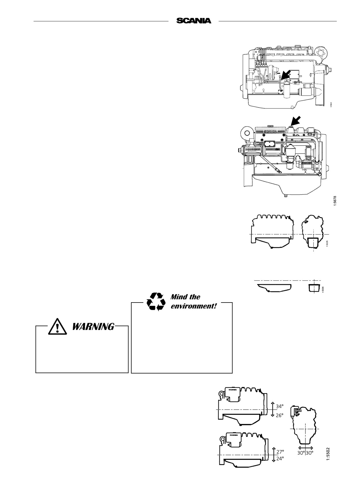
CHECKING THE OIL LEVEL
Note Before checking oil level: Allow the engine to remain stopped for
at least 1 minute.
- The correct level is between the marks on the dipstick. Top up when the
level is at the lower mark.
- Correct type, see "Oil grade" on page 26.
Note Checking of oil level during operation can not be performed on
engines with standard oil sump, see picture.
2. Every 400 hours:
OIL CHANGE
Note Under extremely severe operating conditions, especially in dusty
environment or if the deposits in the centrifugal cleaner are
thicker than 20 mm: change oil more frequently.
- Pump out the oil with the oil bilge pump when the engine is warm.
- Fill up with oil.
- Check the level on the dipstick.
Max 25 dm3
Min 20 dm3
Max 20 dm3
Min 16 dm3
Always use a suitable container
to avoid spillage when
1 dm3 = 1 litre
changing oil.
The oil may be hot.
Dispose of used oil through an
Wear protective gloves and
authorized waste disposal
goggles
contractor.
Maximum angles of inclination during operation
Maximum permissible angles during operation vary, depending on
the type of oil sump, see illustration.
Note Specified angle may only occur intermittently.
2001-05:1
27

3. Every 400 hours:
CLEANING THE OIL CLEANER
(at same time as oil change)
- Unscrew the nut and remove the cover.
Open the cap carefully. The
oil may be hot.
- Lift out the rotor and slacken the rotor bowl retaining nut three turns.
- If the nut is jammed:
Clamp the nut, never the rotor, in a vice and turn the rotor three turns by
hand or with a screwdriver.
- Tap the nut lightly with your hand or a plastic hammer, to detach the
rotor bowl from the bottom plate.
- Unscrew the nut and remove the rotor bowl.
- Prise carefully to detach the strainer from the bottom plate.
- Scrape off the deposits from the inside of the rotor bowl. If there are no
deposits, this indicates that the cleaner is not working properly.
- If the deposits are thicker than 20 mm: clean more often.
28
2001-05:1
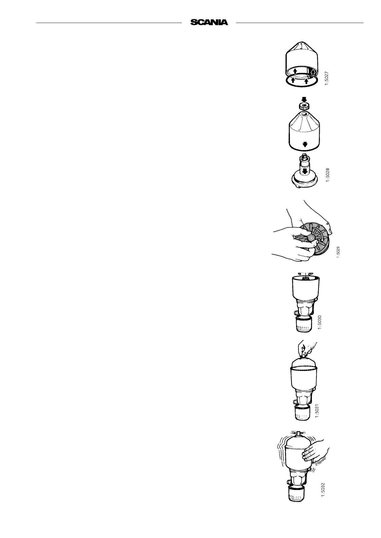
- Clean all parts in diesel fuel..
- Fit the O-ring in the rotor bowl. Make sure it is not damaged.
Change if necessary.
- Assemble the rotor.
- Tighten the rotor nut firmly by hand.
- Refit the rotor.
- Make sure that it spins easily.
- Check that the O-ring in the bowl is undamaged.
Renew the O-ring if hard or damaged.
- Secure the bowl firmly, tightening the nut by hand.
If the nut is tightened with a tool, the rotor shaft, nut or bowl may be
damaged.
Functional test
The rotor spins very fast and should continue to rotate when the engine has
stopped.
- Stop the engine when it is warm.
- Listen for a whirring sound from the rotor or feel whether the cleaner
housing is vibrating.
The rotor normally continues spinning for 30 - 60 seconds after the engine
has stopped.
If not: Dismantle and inspect.
2001-05:1
29

4. Every 400 hours:
CHANGING THE OIL FILTER
(at same time as an oil change)
- Remove the old filter.
- Oil the rubber gasket and fit a new genuine Scania filter.
- Tighten the filter by hand.
Never use a tool for tightening. The filter could be damaged,
obstructing circulation.
- Start the engine and check for leaks.
Important If the deposits in the centrifugal cleaner are thicker than 20
mm the oil filter should be renewed more frequently. This
includes cleaning the centrifugal filter and changing oil.
Always collect oil in a suitable
container to avoid spillage when
renewing the oil filter.
Dispose of used filters through
an authorized waste disposal
contractor.
COOLING SYSTEM
5. Daily:
CHECKING COOLANT LEVEL
Carefully open the cap.
Hot water and steam
- Open the expansion tank filler cap and check the coolant level.
may blow out.
- Correct level: (integral expansion tank in the heat exchanger)
- Cold engine: The coolant level should be 10 - 20 mm under the
expansion tank upper inner part.
- Warm engine: The coolant level should be at the expansion tank
upper inner part.
- Other types of expansion tank according to the installer’s instructions.
Always top up with ready mixed
coolant.
- Top up the coolant as necessary, see point 6.
Note When filling large amounts of coolant:
Never pour cold coolant into a hot engine.
This could cause cracks in the cylinder block and the cylinder
head.
30
2001-05:1
6. Every 400 hours:
CHECKING CORROSION BARS
(Only engines with heat exchanger)
- Empty the sea water circuit and check the corrosion bars (protection
anodes). Located as illustrated.
- Scrape off all loose material on the anode.
- Change if less than half the bar is left.
A new bar is 55 mm long with a diameter of 17 mm.
Important If the corrosion bars are very corroded they need to be
checked more often, for example every 200 hours.
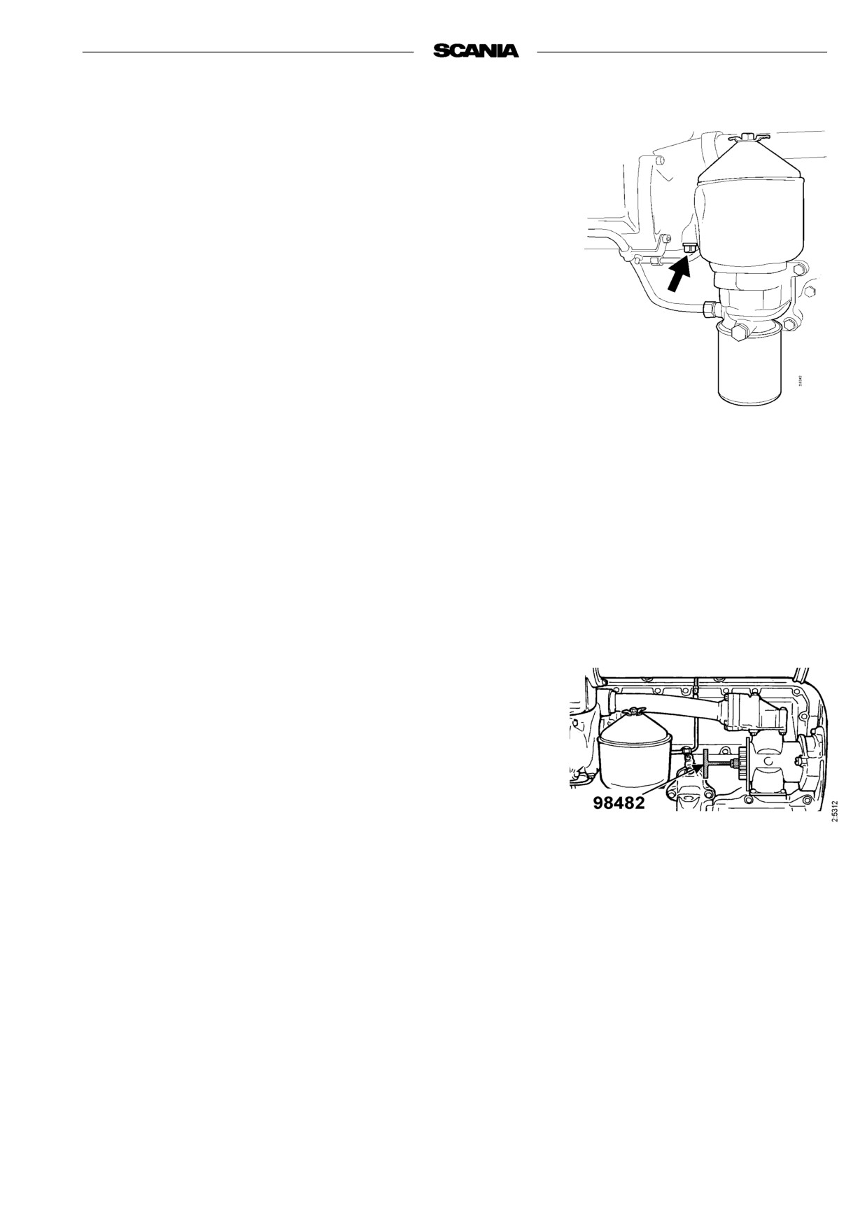
7. Every 400 hours:
CHECKING THE SEA WATER PUMP
IMPELLER
(Only engines with heat exchanger)
- Close the bottom valve if the seawater pump is below the water line.
- Empty the sea water circuit.
- Take off the seawater pump cap.
- Check that the impeller vanes are not worn or damaged.
Important If the impeller must be changed frequently, the cleaning of
the sea water must be improved.
Changing the impeller
- Pull out the impeller with puller 98 482 (Scania Special Tools).
- Fit new impeller and cap. Check that the cap seal is not hard or
damaged.
Note A spare impeller should be kept on board.
- The impeller can be deformed at longer periods of inactivity. Change
before or remove the impeller before longer periods of stoppage. Also
see "Preparations of storage".
2001-05:1
31