Scania D9, DI9. Marine engine. Operator’s manual - part 3


  Index      Scania     Scania D9, DI9. Marine engine. Operator’s manual


Search            copyright infringement  


Content      ..     1      2      3      4      ..


Scania D9, DI9. Marine engine. Operator’s manual - part 3


2001-05:1

Checking 

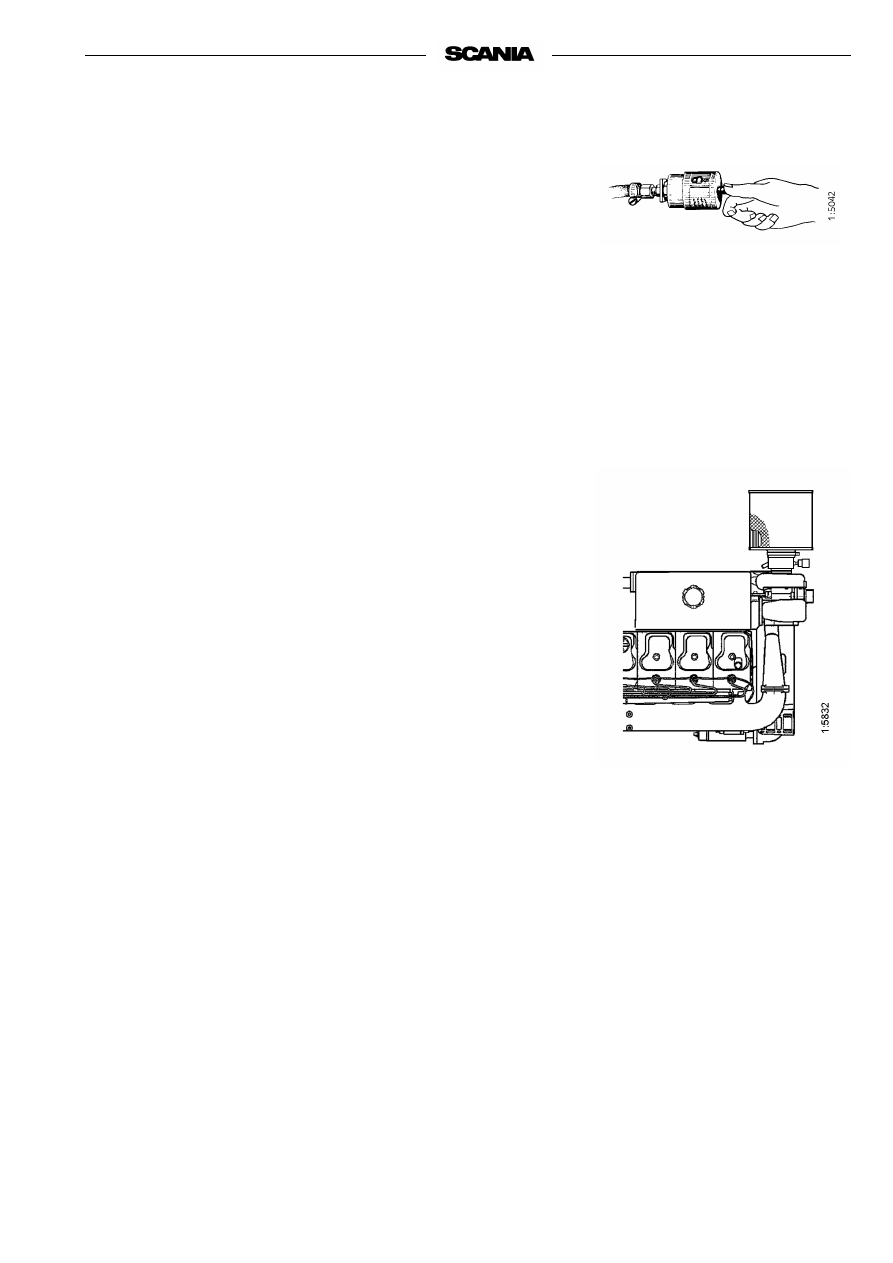
- Insert a flashlamp into the insert and check from the outside that there 

are no holes or cracks in the filter paper.

- Change the filter insert if there is any damage at all. Danger of engine 

damage.

Assembly

1.

Assemble the air cleaner in reverse order.

2.

Reset the red plunger in the vacuum indicator by depressing the button.

Filter with a non-changeable element

 (unit cleaner)


Cleaning 

- The filter may be cleaned a maximum of 3 times. Mark the filter after 

each time it has been cleaned.

- Use a cleaning solution consisting of water mixed with approx. 1% mild 

detergent. 

1.

Pour the cleaning solution into the element outlet at the same time as 
turning the element so that the cleaning solution pours through the 
element against the direction of the air flow.

2.

Leave the element in the cleaning solution for 5 minutes and then take it 
out so that all the cleaning solution drains away.

3.

Rinse the element with ca 30 litres clean water at 30 - 40 °C. Pour the 
rinsing water into the element in the same way as the cleaning solution.

4.

Take out the element and allow the rinsing water to drain off.

5.

Repeat the procedure until the rinsing water is clean.

6.

Leave the element to dry in a warm place for a few days

Note

The element must not be dried with compressed air

.  

34

13. Every 2400 hours: 

CHANGING SAFETY CARTRIDGE

1.

Remove and clean the coarse cleaner, see point 11.

2.

Undo the nut securing the filter insert and remove it. 

3.

Change or clean the filter insert, see point 12.

4.

Undo the nut securing the safety cartridge and remove it. 

5.

Fit a new Scania genuine safety cartridge. 

6.

Assemble the air cleaner. 

1.

Pre-filter with cover

2.

Filter insert

3.

Low pressure indicator

4.

Safety cartridge

Air cleaner with pre-filter

Do not remove the safety 

cartridge unnecessarily.

Never clean the safety cartridge

2001-05:1

FUEL SYSTEM 

14. Daily:

CHECKING FUEL LEVEL 

- Top up fuel if necessary.

- If the tank is run dry, bleed the fuel system, see point 15.

Be extremely careful with 

cleanliness when working on 

the fuel system.

Malfunctions

 can easily arise and the 

injection equipment

 can be damaged. 

15. Every 1200 hours:

CHANGING THE FUEL FILTER

Fuel tanks

- Drain any water from the fuel tanks.

Main filter 

The filter consists of a filter unit.

- Wash the outside of the filter and unscrew it.

- Fit the new filter and tighten it by hand.

Never use tools for this. The filters can be damaged,
obstructing circulation. 

- Bleed the fuel system as described below.

- Start the engine and check for leaks.

Bleeding the fuel system

- Open the bleed screw 1 on the main filter. 

- Pump the hand pump 2 until air-free fuel flows out at the maim bleed 

screw. 

- Close the bleed screw. Pump a few times using the hand pump. 

If the engine is difficult to start after bleeding . . . . .  

- Slacken the injection pump overflow valve 3 one half turn

and try starting again. On the 8000 pump, the overflow valve is located 
on the fuel shut-off valve. 

If the engine still won’t start . . . . . . . 

- Pump the hand pump until bubble-free fuel flows from the overflow 

valve.

- Tighten the overflow valve when the engine has started. 

1

2

3

Always collect fuel in a suitable 

container to avoid spillage when 

bleeding system or renewing 

components.

Only use Scania genuine fuel 

filter.

36

16. Every 2400 hours: 

CHECKING THE INJECTORS

Injectors should be inspected by trained personnel with access to the neces-
sary equipment. Inspection should be carried out at least once a year or every 
2400 hours. 

Removal

1.

Clean round the injectors and connections, including clamps and 
brackets.

2.

Detach the delivery pipe bundle and leak-off fuel lines.

3.

Unscrew the injector.

4.

Fit protective plugs on the injector and delivery pipe.

5.

Lift up the seal from the bottom of the injector seat if it does not come 
out together with the injector.

6.

Fit a core plug in the injector seat in the cylinder head.

7.

Clean the injectors and check/adjust in a nozzle tester

Correct opening pressure, see Technical data, page 49. 

Fitting 

1.

Check that there is no old seal in place and fit a new seal in the bottom 
of the injector seat.

2.

Fit a new O-ring in the threaded socket nut and a new seal under the 
socket nut.

3.

Fit the injector.

4.

Tighten the socket nut to 70 Nm (7.0 kpm).

5.

Fit the delivery pipe and tighten the union nuts to 20 Nm (2.0 kpm). Fit 
clamps and brackets.

Important

Take care to fit the delivery pipe without tension and make sure 
that the cone on it is correctly positioned in the connection.

6.

Fit the leak-off fuel line. Tighten the bolts to 11 Nm (1.1 kpm)

1.

Socket nut 

2.

O-ring 

3.

O-ring 

4.

Stop ring 

5.

Guide pin 

6.

Seal 

The delivery pipes must

not be bent.

All clamps must be refitted.

Always wear gloves and eye 

protection when testing 

injectors.

Fuel escaping under high 

pressure can penetrate body 

tissue and cause serious injury.

1.

Delivery pipes 

2.

Cap nut 

3.

Washer 

4.

Cone 

5.

Connector on injector or 
injection pump 

Delivery pipe connection 

2001-05:1

ELECTRICAL SYSTEM 

17. Every 200 hours: 

CHECKING THE
ELECTROLYTE LEVEL IN BATTERIES 

1.

Undo the plugs and check the electrolyte level in all cells. 

2.

Top up with distilled water until the level is 10-15 mm above the plates. 

18. Every 200 hours: 

CHECKING THE STATE OF CHARGE
IN BATTERIES 

Note

Every 200 hours applies to gensets and the like. Other installa-
tions every 1200 hours. 

- Check the density with an acid tester. 

In a fully charged battery it should be: 

1,280 at +20 °C 

1,294 at 0 °C 

1,308 at -20 °C 

- If the density is below 1.20, the battery must be charged. 

A discharged battery freezes at -5 °C. 

Do not 

rapid-charge the batteries. This will damage the battery in the

long run. 

19. Every 200 hours: 

CLEANING BATTERIES 

Note

Every 200 hours applies to gensets and the like.Other installa-
tions every 1200 hours. 

1.

Clean batteries, cables and cable terminals. 

2.

Check that all cable terminals are firmly tightened

3.

Grease battery terminal posts and cable terminals with vaseline

Wear gloves and eye protection 

when charging and

handling batteries.

Batteries contain a highly 

corrosive acid.

Do not connect the cables to the 

wrong terminals.

This could cause serious 

damage to the electrical system.

If the terminals are

shortcircuited, sparks

will be generated. 

Do not let open flame or sparks 

come near the batteries.

When batteries are charged, 

they emit highly flammable 

fumes that can explode.

38

20. Every 1200 hours:

CHECKING THE COOLANT
LEVEL MONITOR 

(optional equipment) 

Note

Check the coolant level monitor when the engine is cold.

1.

Loosen the coolant level monitor cable clamps towards the cable cluster 
and disconnect the connector.

2.

Put a container under the heat exchanger and unscrew the monitor. 
Immediately insert a threaded plug M18x1.5 in the hole for the 
monitor. Avoid contact with the skin when handling coolant.

3.

Connect the monitor connector and put the control switch in the "ON" 
position.

4.

Check that the warning lamp remains on and that the buzzer sounds 
(if fitted).

5.

Lower the monitor into a metal container (steel) with liquid. It is 
important that the monitor body is in contact with the metal.

6.

After approximately 2 seconds the warning lamp should go out.

7.

Remove the monitor from the liquid. After approximately 7 seconds the 
warning lamp will come on and the buzzer sound (if fitted).

8.

Disconnect the monitor connector and screw on the monitor again.

9.

Clamp the monitor cable as before and connect the connector.

10.

Top up the system with coolant according to the specification on 
page 26. 

2001-05:1

21. Every 1200 hours: 

CHECKING THE TEMPERATURE 
MONITOR

1.

Drain the coolant, allowing the temperature monitor to be removed. 

2.

Remove the temperature monitor cable(s). 

3.

Unscrew the monitor. 

4.

Refit the cable(s) to the monitor. 

5.

Submerge the monitor sensor body in water. Heat the water slowly 
(about 1° per minute) using e.g. an immersion heater. 

6.

Set the control switch to "ON". Use a thermometer to check that the 
warning lamp comes on or that an alarm is initiated at the correct tem-
perature. 

The correct temperature is stamped on the hexagonal part of the 
monitor. 

The temperature tolerance is ± 3°. 

CHECKING TEMPERATURE SENSOR

1.

Drain the coolant, allowing the temperature sensor to be removed.

2.

Remove the temperature sensor cable(s).

3.

Unscrew the sensor.

4.

Connect an ohmmeter to the temperature sensor.

5.

Submerge the sensor body in water. Heat the water slowly
(approximately 1° per minute) using e.g. an immersion heater.

6.

Check the resistance at the temperatures given below.

7.

The sensor should give the following readings

At temp. °C

Resistance 

Tolerance °C

60

134 

± 13.5

±4

90

51.2 

± 4.3

±3

100

38.5 

± 3

±3

2-pole temperature sensor 

C = Common connection 

1 =  Connection C -1 closes at 

stamped temperature 

2 = Connection C -2 opens at 

stamped temperature 

2-pole temperature monitor 

Always use a suitable container 

to avoid spillage when

draining coolant.

Dispose of used coolant through 

an authorized waste disposal 

contractor.

40

22. Every 1200 hours: 

CHECKING THE OIL PRESSURE 
SENSOR/MONITOR

Sensor function

Measure the sensor output voltage (pin 3) at different oil pressures. The 
sensor output voltage shall be as follows:

0.85-1.15 bar = 2.45 volt
1.80-2.20 bar = 3.70 volt
2.75-3.25 bar = 4.50 volt
3.79-4.20 bar = 5.20 volt
4.55-5.45 bar = 5.70 volt
5.40-6.6 bar

= 6.10 volt

The tolerances apply at +30°C - 110°C. At lower temperatures the tolerance 
range is wider, e.g. 0°C = x 1.4.

Monitor function

Connect a test lamp to the oil pressure monitor, pin 4 (

-

 ground), and check 

that the monitor switches on at the correct pressure when the engine is started 
and stopped. The monitor shall switch on at 0.7 

± 0.15 bar when the engine is 

stopped.

Important

The sensor/monitor must be supplied with voltage during the 
measurement. Maximum 4 W load from a test lamp.

Monitor connected for automatic stop in case of a fault: 

1.

Start the engine. 

2.

Check on the oil pressure gauge that oil pressure rises. 

3.

Stop the engine manually (using the emergency stop). 

4.

Check on the oil pressure gauge at what pressure the stop solenoid oper-
ates and the monitor opens. Correct pressure: 0.7 

± 0.15 bar. 

Monitor connected to buzzer: 

1.

Main power switch in operating position, check that buzzer sounds. 

2.

With the engine running, check that the buzzer falls silent when the oil 
pressure is above 1.1 

±0.15 bar and the monitor closes.

23. Every 400 hours: 

CHECKING THE STOP FEATURE 

Check that the stop solenoid is activated and stops the engine when the stop 
signal is given by the button, temperature monitor, coolant level monitor and 
oil pressure monitor if these are coupled for automatic stop in the case of 
fault. 

Important

Stop solenoids with a timer module may be activated for start 
and stop a maximum of 3 times per minute. Otherwise, the 
timer module may be damaged and the stop feature cease. 

4

1

3

2

2001-05:1

CHECKING STOP SOLENOID STOP POSITION 

When changing the stop solenoid, or if the stop feature is not satisfactory, the 
following should be done (the figures show the stop control with the engine 
in stop position): 

The stop position at “Pull to stop”. 

- Check and/or set the length of the link rod so that the distance between 

the locknuts (nut height 5.2 mm) is 21.0 

±


0.1 mm when the nuts are 

tightened. 

- Fit the stop solenoid in the bracket as in the figure. 

- Connect the stop solenoid electrically, red to battery 

+

 and black to

battery 

-

, and activate it so that it is fully pulled. Note: Pole reversal 

will damage the timer module

- Screw the clevis onto the stop lever using the link pin and check, in stop 

position, that there is a small clearance (0.2-0.3 mm) between the stop 
lever and the operating point on the governor 

- Check the stop feature by starting the engine and then stopping it by 

activating the stop solenoid. 

Important

The stop solenoid must not be activated more than 3 times per 
minute as the timer module can be damaged. 

Stop position at “Pulled during operation”. 

- Check and/or set the length of the link rod so that the distance between 

the locknuts (nut height 5.2 mm) is 26.0 

±0.1 mm when the nuts are 

tightened. 

- Fit the stop solenoid in the bracket as in the figure. 

- Connect the stop solenoid electrically, red to battery 

+

 and black to

battery 

-

, and activate it so that it is fully pulled. Note: Pole reversal 

will damage the timer module

- Turn the stop lever to operating position and screw the clevis onto the 

stop lever using the link pin and check, in operating position, that there 
is a small clearance (0.2-0.3 mm) between the stop lever and the opera-
ting point on the governor 

- Activete the stop solenoid and start the engine. Stop the engine by cut-

ting the power to the stop solenoid. 

Important

The stop solenoid must not be activated more than 3 times per 
minute as the timer module can be damaged.


Installation “Pull to stop” 

Installation “Pulled during

operation” 

42

RENEWING THE BATTERY

Removal

1.

Disconnect the negative cable (-) from the battery (cable connected to 
ground).

2.

Disconnect the positive cable (+) from the battery (cable connected to 
starter motor).

Fitting

1.

Connect the positive cable (+) to the battery (cable connected to starter 
motor).

2.

Connect the negative cable (-) to the battery (cable connected to 
ground). 

MISCELLANEOUS

24. Every 1200 hours:

CHECKING THE DRIVE BELT

Replace the drive belt (1) (poly V-belt) if worn or damaged.

Also check that the automatic belt tensioner (2) is working and keeps the 
drive belt correctly tensioned.

2

1

Do not connect the cables to the 

wrong terminals.

This could cause serious 

damage to the electrical system.

If the terminals are short-

circuited, sparks will be 

generated. 

Dispose of used batteries 

through an authorized waste 

disposal contractor.

2001-05:1

25. Daily: 

CHECKING FOR LEAKAGE, RECTIFY 
AS NECESSARY

- Start the engine. 

- Check for oil, coolant, fuel, air and exhaust leakage. 

- Tighten or change leaking connections. Check the overflow holes (1) 

which show whether the O-rings between the cylinder liner and crank-
case are leaking, see drawing. 

a) If coolant is leaking out, the two upper O-rings are leaking. 

b) If oil is leaking out, the lower O-ring is leaking. 

A small amount of leakage from the overflow holes during the engine 
running-in period is normal. (Seals and O-rings are lubricated with soap 
or oil when fitted). 

This leakage normally stops after a time. 

1

In case of major leakage, 

contact the nearest Scania 

workshop.

Ensure that any leakage does 

not pollute the environment. 

44

26. Every 2400 hours:

CHECK/ ADJUST
VALVE CLEARANCE


Note

Checking/adjusting valve clearances should also be carried out 
after the first 400 hours of operation. 

Valve clearances should be adjusted when the engine is cold, at least 30 min-
utes after running. 

Rocker cover gaskets should be changed as necessary. Tightening torque: 
25 Nm.

Intake valve clearance: 0.45 mm
Outlet valve clearance: 0.80 mm.

Alternative 1 

- Set No. 1 cylinder to TDC by turning the engine in its direction of rota-

tion until both valves are closed. 

- Adjust the following valves. Correct valve clearance is indicated on the 

instruction plate on one of the rocker covers: 

Cylinder 1

Intake and exhaust


2

In


3

Ex


4

In


5

Ex 

- Set No. 6 cylinder to TDC by turning the engine one revolution in its 

direction of rotation. 

- Adjust the following valves: 

Cylinder 2

Ex


3

In


4

Ex


5

In


6

In and ex 

Covers for reading 
on flywheel casing 

Note 

Readings can either be taken 

from underneath or from 
above, depending on which 
flywheel is used. 

The cover not being used is 

covered with a seal and an 
instruction plate. 

TDC 

No. 6 cyl 

TDC 

No. 1 cyl 

Intake valve 

Exhaust valve 

5

4

3

2

1

6

FLYWHEEL

FLYWHEEL

WARNING

Immobilise the starting device 

when working on the engine.

If the engine starts out of 

control, there is a

SERIOUS RISK 

OF INJURY.

2001-05:1

Alternative 2 

- Set the No. 1 cylinder to TDC by turning the engine in its direction of 

rotation until both valves are closed. 

- Adjust both the valves for the No.1 cylinder. Correct valve clearance is 

indicated on the instruction plate on one of the rocker covers.

- Repeat this procedure with the remaining cylinders in the order 

5 - 3 - 6 - 2 - 4 (firing sequence) by turning the engine 1/3 revolution in 
its direction of rotation between each adjustment. 

27. Every 2400 hours: 

CHANGING (or CLEANING) THE 
CLOSED CRANKCASE VENTILATION 
VALVE 

Alternative 1: 

Change the valve at the specified interval. 

Alternative 2: 

- Remove the valve after the specified interval. 

- Clean the valve by placing it in a bath of diesel oil overnight. Then rinse 

it several times in diesel and allow it to drip dry. 

- Refit the valve. 

- The valve may be reused (cleaned), maximum twice after the initial 

2400 hours of operation. Take care to mark the valve after cleaning it. 

LONG-TERM STORAGE

If the engine is not to be used for a lengthy period of time, special measures 
should be taken to protect the cooling system, fuel system and combustion 
chamber from corrosion and the exterior from rusting.

The engine can normally stand idle for up to six months. If it remains unused 
for longer than this the following measures, which provide protection for 
about four years, should be adopted. An alternative to preparing the engine 
for long-term storage is to start the engine and warm it up every 6 months.

Preparing the engine for long-term storage means:

- Thoroughly cleaning the engine

- To run the engine for a period of time with preservative fuel, 

preservative oil and preservative coolant.

- Otherwise preparing the engine for storage (filter changes, lubrication, 

etc.).

Preservative coolant

If the engine is to be stored with a full cooling system, use coolant containing 
50% glycol by volume. Glycol without nitrite-based inhibitor must be used.
E.g. BASF G48 or BASF D542.

Preservative fuel

- Use diesel fuel mixed with Lubrizol 560A or equal.

- Mix  1  cm

3

 (ml) of Lubrizol 560A with 10 dm

3

 (l) of fuel.

HANDLING LUBRIZOL 560A

Hazardous!

Contains aromatic hydrocarbons

Use spot extractors where there is a danger of vapour build-up.

Wear protective gloves and goggles when handling Lubrizol. Do not use contaminated clothing.

In case of splashes in the eye: Rinse with moderate water spray (for min. 15 minutes). Seek medical attention.

In case of skin contact:

Wash affected areas with soap and water.

If you inhale it:

Fresh air, rest and warmth

Flammable:

Fire class 2A. Flash point + 27°.
In case of fire: Extinguish using carbonic acid, powder or foam

Storage:

In properly sealed container in a dry, cool place. Keep out of reach of children.

!

Ethylene glycol, if swallowed 

can be fatal.

Avoid contact with the skin.

2001-05:1

Preservative oil


Suitable preservative oil can be supplied by most petroleum companies.

For example: Dinitrol 40 or the equivalent

Preparations for storage


- Drain and flush the cooling system. Top up with preservative coolant.

- Warm up the engine on regular fuel. Stop the engine and drain the oil.

- Change the fuel filter and turbo filter.

- Fill the engine with preservative oil up to the minimum level on the 

dipstick.

- Mix preservative fuel in a can. Detach the fuel pipe at the feed pump 

suction line and connect a hose from the can.

- Detach the fuel pipe at the overflow valve and connect a return hose to 

the can.

- Start the engine and run it at approximately 1000 rpm (not single-speed 

engines) for 20-25 minutes.

- Stop the engine, remove the hoses and connect the normal fuel lines.

-

Oil the valve mechanism generously with preservative oil.

- Remove the injectors and spray preservative oil into each cylinder, 

max 30 cm

3

 (ml)

Turn the engine over a few times using the starter motor. Spray an 
additional small amount of oil into each cylinder. 
After this the engine must not be cranked. Refit the injectors.

- Drain the preservative oil from the engine. Fresh engine oil can be filled 

directly or when the engine is taken out of storage.

- Drain the coolant if the engine is not to be stored with a full cooling 

system. Plug and tape over all coolant connections (if the cooling system 
is not completely assembled).

- Air cleaner: Clean or change the filter element.

- Cover air intakes and exhaust pipes.

- Alternator and starter motor:

- Spray with water-repellent anti-corrosive oil, CRC 226, LPS1 or equal.

- Spray the outside of bright metal engine parts, first with penetrating pre-

servative oil such as Dinitrol 25B and then with Dinitrol 112 or equal.

Winter storage

- In order to minmize the risk of condensation water in the fuel tank 

during a winter stop it should be filled with fuel.

Always use suitable containers 

to avoid spillage when

draining oil and coolant.

Dispose of used oil and coolant 

through an authorized waste 

disposal contractor.

48

- Attach a label to the engine showing the date of preservation and 

clearly stating that it must not be started or cranked. 

Batteries 

Remove the batteries for trickle charging at a charging station. (This does not 
apply to batteries which, according to the manufacturer, are maintenance 
free.) The same is applicable for short-term storage if the engine has not been 
prepared for storage as above. 

Storage

After the preparations, the engine should be stored in a dry and warm place
(room temperature). 

Taking out of storage 

(Procedure when the engine is to be put into operation)

- Remove plugs and tape from coolant connections, air intakes and 

exhaust pipes.

- Fill the system with coolant, see page 12.

- Check the oil level in the engine or top up with new motor oil.

- Turn the engine over a few times with the injectors removed, at the same 

time copiously oiling the valve mechanism with pushrods and tappets. 

Important

The engine must be turned over with the injectors removed so 
that surplus preservative oil will be pressed out of the cylinders. 

- Fit the injectors.

- Empty the fuel system main filter of preservative oil.

- Bleed the fuel system.

- Wash off any externally applied preservative oil, using white spirit. 

STORED ENGINE

Date . . . . . . . . . . .

Do not start or crank!


Wear gloves and eye protection 

when charging and handling 

batteries.

Batteries contain a highly 

corrosive acid.

Always use suitable containers 

to avoid spillage when

draining oil and coolant.

Dispose of used oil and coolant 

through an authorized waste 

disposal contractor.


Content      ..     1      2      3      4      ..