Scania DC9 EMS with S6/PDE. Industrial engine. Operator’s manual - part 3


  Index      Scania     Scania DC9 EMS with S6/PDE. Industrial engine. Operator’s manual


Search            


Content      ..     1      2      3      4      ..


Scania DC9 EMS with S6/PDE. Industrial engine. Operator’s manual - part 3


33

- Wash all parts in diesel oil.
- Make sure the nozzles on the rotor are not blocked or damaged.
- Check that the bearings are undamaged. If they are damaged the entire 

rotor must be renewed.

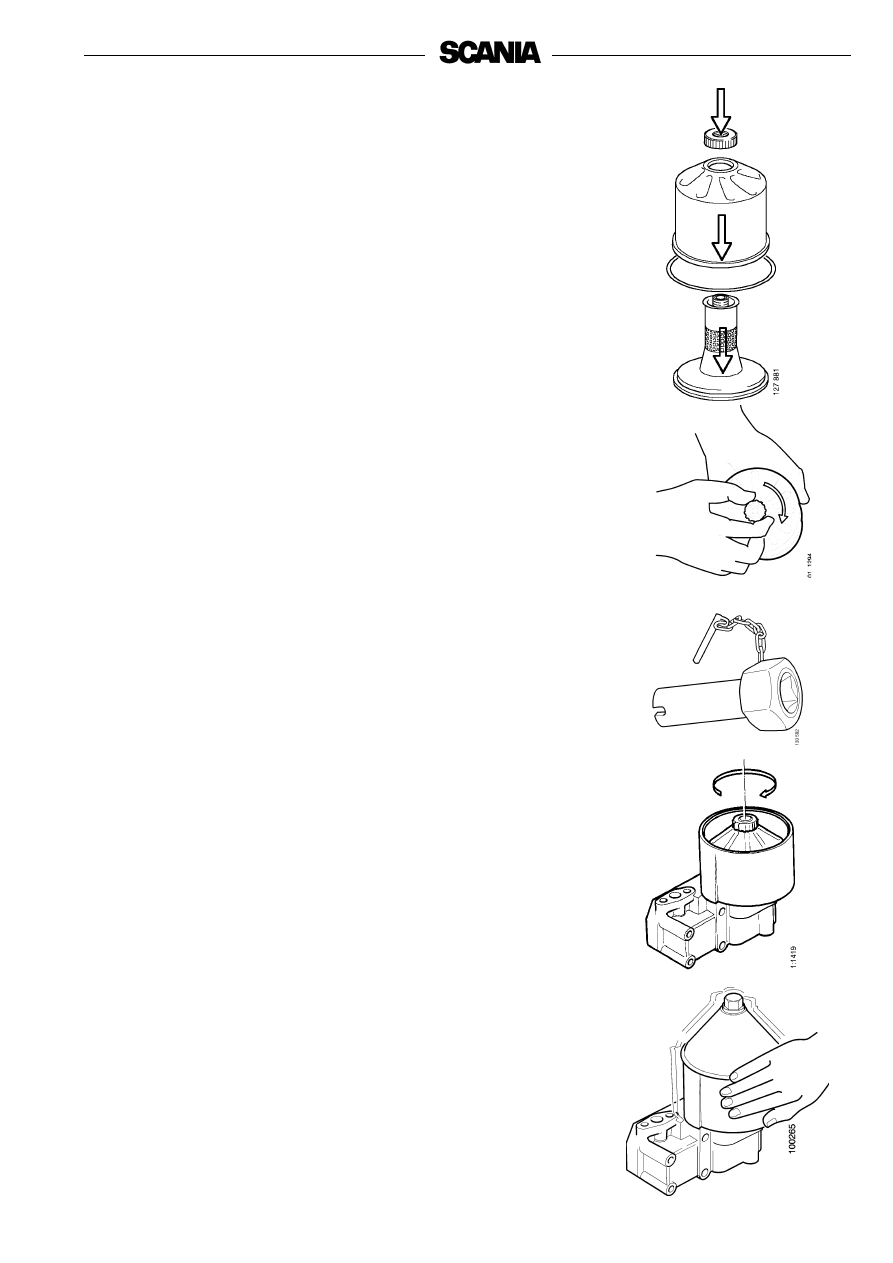
- Fit a new O-ring on the rotor and fit the strainer.

- Reassemble the rotor.

- Tighten the rotor nut firmly by hand.

- Check that the shaft is not loose. If it is loose, use locking compound 

561 200 and torque tighten the shaft to 34 Nm using tool 98 421.

- In order to tighten the rotor shaft, it is necessary to modify socket 

wrench 98 421:

- Drill out the threads from a M20 nut so that it fits on the square drive 

of the socket wrench.

- Weld the nut into place.

- Refit the rotor.
- Check that it rotates easily by rotating it manually.

- Fit a new O-ring on the cover and fit the cover.
- Screw the bowl on and tighten the lock nut to 15 Nm.

Tighten the nut carefully so as not to damage the rotor shaft, nut or cover.

Functional inspection

The rotor rotates very fast and should continue to rotate when the engine has 

stopped.

- Stop the engine when it is warm.
- Listen for a whirring sound from the rotor or feel whether the cleaner 

housing is vibrating.

The rotor normally continues spinning for 30-60 seconds after the engine has 

stopped.
If not: dismantle and check.

34

4. Every 400 hours:

Renewing the oil filter 

(in connection with oil change)

- Remove the old filter.
- Fit a new Scania genuine filter. Oil the seal on the filter before fitting.
- Tighten the filter by hand. Never use tools, the filter could sustain 

damage, obstructing circulation.

- Start the engine and check for leaks.

Important!

If the deposits in the centrifugal cleaner are more than 

28 mm thick, the oil filter must be renewed more often. The 

same is true for cleaning the centrifugal filter and changing 

the oil.

Cooling system

5. Daily:

Checking coolant level

- Open the expansion tank filler cap and check the coolant level.
- Correct level:  (Scania plastic expansion tank)

- Cold engine: The coolant should be level with the bottom of the 

filler neck.

- Hot engine: The coolant should be about 25 mm above the lower 

edge of the filler hole.

- Other types of expansion tank according to the instructions of the fitter.
- Top up the coolant as necessary; see point 6.

Note:

When filling large amounts of coolant:

Never add cold coolant to a hot engine. Risk of cracks forming in 

the cylinder block and cylinder head.

Use a container to avoid spillage 

when renewing the filter.

Dispose of used filters through 

an authorised waste disposal 

contractor.

Always top up with pre-mixed 

coolant.

Open the cap carefully.

Water and steam can spray out.

Important

!

WARNING

!

Help protect our 

environment!

35

6. Every 2,400 hours:

Checking coolant

Coolant should be checked as follows:

a)

Check the appearance of the coolant.

b)

Coolant with glycol only: check the glycol content.

c)

Coolant containing only Scania Corrosion Inhibitor: check the corrosion 

inhibitor content.

The composition of the coolant is described in more detail under 

"Starting and running".

a)
Checking the appearance of the coolant

- Pour a small amount of coolant in a container, and check that the coolant 

is pure and clear.

- If the coolant is contaminated or cloudy: consider changing the coolant.
- Water for the coolant must be clean and free from contamination.
- Use drinking water with a pH of 6-9.

b)
Checking the glycol content

If there is a danger of freezing, use only glycol as an anti-corrosive in the 

coolant.

- Cooling systems with glycol should contain at least 30% glycol by 

volume to provide acceptable protection against corrosion.

- 30% glycol by volume provides protection against freezing to -16°C. 

If additional protection against freezing is required, see the table on the 

next page to help you calculate how much glycol you need.

We recommend only nitrite-free antifreeze glycols with the following 

supplier designations:

BASF G48 or BASF D542

- Always add glycol if the glycol content drops below 30% by volume. A 

glycol content above 60% by volume will not provide greater protection 

against freezing.

- The table shows the temperature at which ice starts to form. The engine 

will freeze and break at appreciably lower temperatures; see diagram.

- Ice forming in the coolant often causes malfunctioning without any risk 

of damage. The engine should not be subjected to heavy loads when ice 

starts to form.

Note:

The coolant should be changed when the cooling system is 

cleaned: every 4,800 hours or at least every 5 years.

Important!

If a coolant filter is used in the cooling system it must not 

contain an inhibitor.

Coolant composition:

If there is a danger of freezing:

minimum 30% glycol by 

volume

maximum 60% glycol by 

volume

If there is no danger of freezing:

8-12% by volume

Scania Corrosion Inhibitor

The coolant should be pre-

mixed when it is poured into the 

cooling system.

Never top up with only water or 

only glycol.

Ethylene glycol is highly 

dangerous if imbibed and can 

prove fatal.

Avoid skin contact with glycol.

The recommended glycols must 

not be mixed with glycol 

containing nitrite-based 

corrosion inhibitor.

Risk of sludge build-up and 

reduced cooling capacity.

Important

!

Important

!

WARNING

!

36

Curve A: Ice formation starts (ice slush)
Curve B: Temperature at which there is a risk of damage by freezing

1. Safe range
2. Malfunctions may occur (ice slush)
3. Risk of damage by freezing

Characteristics of glycol at low temperatures:

- Example with 30% glycol by volume
- Ice slush starts to form at -16°C.
- There is a risk of malfunctions at -30°C
- No risk of damage by freezing with a minimum 

content of 30% glycol by volume

Antifreeze glycol, % by volume

A

A = Area to be avoided. Only for calculating glycol mix.

Coolant freezing point (when ice starts to form) for different glycol mixes

Glycol % by 

volume

15

20

25

30

35

40

45

50

60

Cooling 

system 

volume, dm

3

Ice slush starts to 

form at °C

-6

-9

-12 -16 -22 -27 -36 -46 -55

Glycol dm

3

(litres)

5

6

8

9

11

12

14

15

18

30

6

8

10

12

14

16

18

20

24

40

8

10

13

15

18

20

23

25

30

50

9

12

15

18

21

24

27

30

36

60

11

14

18

21

25

28

32

35

42

70

12

16

20

24

28

32

36

40

48

80

14

18

23

27

32

36

41

45

54

90

15

20

25

30

35

40

45

50

60

100

17

22

28

33

39

44

50

55

66

110

18

24

30

36

42

48

54

60

72

120

20

26

33

39

46

52

59

65

78

130

21

28

35

42

49

56

63

70

84

140

23

30

38

45

53

60

68

75

90

150

24

32

40

48

56

64

72

80

96

160

26

34

43

51

60

68

77

85

102

170

27

36

45

54

63

72

81

90

108

180

29

38

48

57

67

76

86

95

114

190

30

40

50

60

70

80

90

100 120

200

37

c)
Checking the corrosion inhibitor

There must always be sufficient corrosion protection (inhibitor) in the coolant 

to protect the cooling system against corrosion.
If there is no danger of freezing, only Scania Corrosion Inhibitor should be 

used in the coolant.
The inhibitor in Scania Corrosion Inhibitor is free of nitrites.
The correct corrosion inhibitor content is 8-12% by volume. 

- Topping up with 1.0% Scania Corrosion Inhibitor by volume should be 

done after every 2,400 hours of operation.

- Never top up with water alone or corrosion inhibitor alone!

Fluid losses must always be replaced with pre-mixed coolant: water 

+ 10% Scania Corrosion Inhibitor by volume.

Note:

The coolant should be changed when the cooling system is 

cleaned: every 4,800 hours or at least every 5 years.

Changing coolant

1.

Remove the filler cap from the expansion tank.

2.

The coolant is drained at two points:

- the lowest point of the cylinder block; see illustration
- the lowest point of the cooling system. 

3.

Close the cocks.

4.

Top up with coolant through the expansion tank’s filler hole.
Mix coolant as described on page 31.

Use a container to avoid spills 

when changing the coolant.

Dispose of used coolant through 

an authorised waste disposal 

contractor.

If a coolant filter has been fitted 

it must not contain inhibitor.

Mixing with glycol or the use of 

too much corrosion protection 

can lead to build up of sludge 

and reduced cooling capacity.

Corrosion protection is highly 

dangerous if ingested and can 

prove fatal.

Avoid contact with the skin.

Important

!

Important

!

WARNING

!

Help protect our 

environment!

38

7. Every 4,800 hours:

Cleaning the cooling system

Note:

If necessary, the cooling system should be cleaned more often.

External cleaning

Radiator and charge air cooler

- Check that the radiator and the charge air cooler are not clogged on the 

air side and that the cooling fins are not damaged.

- Carefully scrape the deposit off the radiator’s cooling fins. If necessary, 

a paraffin-based engine cleaner can be used.

- Bent fins can be straightened using a wire brush, for example, and 

exercising care.

The cooling system must never 

be cleaned with caustic soda.

There is a risk of damage to 

aluminium parts.

Important

!

39

Internal cleaning

Removing oil and grease

- If possible, run the engine until it has reached operating temperature and 

then drain the cooling system.

- Remove the thermostats.
- Fill the system with clean, hot water mixed with liquid dishwasher 

detergent designed for household use.

Concentration 1% (0.1/10 l).

- Run the engine until warm for about 20-30 minutes. Do not forget the 

cab heating system (if fitted).

- Drain the cooling system.
- Refill the system with clean hot water and run the engine for about 

20-30 minutes.

- Drain the water from the system.
- Refit the thermostats.
- Top up the system with coolant according to the specification on 

page 31.

Removing deposits

- If possible, run the engine until it has reached operating temperature and 

then drain the cooling system.

- Remove the thermostats.
- Fill the system with clean, hot water mixed with some of the radiator 

cleaning agent available on the market which is based on sulphamic acid 

and contains dispersing agents. Follow the manufacturer’s instructions 

for the concentration and cleaning period.

- Run the engine for the specified time and then drain the cooling system.
- Refill the system with hot water and run the engine for about 

20-30 minutes.

- Drain the water from the system.
- Refit the thermostats.
- Top up the system with coolant according to the specification on 

page 31.

When handling cooling system 

detergent:

read the warning text on the 

containers.

Use a container to avoid spills 

when changing the coolant.

Dispose of used coolant through 

an authorised waste disposal 

contractor.

WARNING

!

Help protect our 

environment!

40

9. Every 200 hours:

Cleaning the air cleaner coarse cleaner

1.

Remove the cover from the coarse cleaner (2).

2.

Remove the conical coarse separator. Empty out the particles of dirt and 

clean it.

3.

Fit the coarse cleaner as shown in the figure and screw the cover into 

place.

10. Every 1,200 hours:
Cleaning or changing filter element

Note:

Clean or renew the filter element earlier if the vacuum indicator 

shows red. 

Dismantling

1.

Remove the cover (3) from the coarse cleaner.

2.

Renew or clean the filter element.

Note:

There is always a risk that the filter element will be damaged 

during cleaning. The element can only be cleaned a maximum of 

four timesAfter cleaning, it has poorer dust capacity than a 

new filter element.

3.

Mark the filter when it has been cleaned.

Cleaning the filter element

- Carefully blow the filter element clean using dry compressed air from 

the inside.

Note:

The filter element must not be washed with water.

Air cleaner

8. Daily:

Test reading of vacuum indicator

If the indicator’s red plunger is fully visible, change or clean the air cleaner 

filter element, point 10. This is especially important if the engine is run with a 

heavy load or at high speed.

4

3

2

1

1.

Filter element

2.

Coarse cleaner

3.

Cover

4.

Vacuum indicator

The coarse cleaner must always 

be fitted in an upright position.

Only use genuine Scania air 

filters.

Renew the filter element if it is 

damaged.

Danger of engine damage if the 

filter element is damaged.

Never start the engine without 

the air filter.

There is a risk of injury or 

serious engine damage.

Important

!

Important

!

WARNING

!

41

Check

- Insert a torch into the element and check from the outside that there are 

no holes or cracks in the filter paper.

- Renew the filter element if it has the slightest damage. Danger of engine 

damage.

Assembly

1.

Assemble the air cleaner in reverse order.

2.

Reset the vacuum indicator by pressing the button.

11. Every 2,400 hours:
Renewing the safety cartridge

Note:

Not all filters are equipped with a safety cartridge. When 

changing the safety cartridge, take great care to ensure that no 

dirt or other impurities can get into the engine.

1.

Remove the cover from the air cleaner.

2.

Remove the filter element.

3.

Remove the safety cartridge.

4.

Fit a new genuine Scania safety cartridge.

5.

Renew or clean the filter element, see point 10.

6.

Assemble the air cleaner.

1

Do not remove the safety 

cartridge unnecessarily.

1. Safety cartridge

Air cleaner with safety cartridge

Never clean the safety cartridge.

Important

!

Important

!

42

Fuel system

12. Daily:
Checking fuel level

- Top up with fuel if necessary.
- If the tank has been run dry, bleed the fuel system, see point 13.

13. Every 1,200 hours:
Renewing the fuel filter

Fuel tanks

- Drain any water from the fuel tanks.

Main filter

- Unscrew the filter cover with a closed tool with hexagon driver, for 

example socket 587 637, so as not to damage the filter cover.

- Lift out the filter lid and filter element. At the same time, the filter 

housing will drain automatically. This applies only if the fuel tank is 

lower than the engine. Otherwise the fuel shut-off cock must be closed 

first.

- Remove the filter element from the lid by carefully prying it to one side. 

Discard the filter according to environmental requirements.

- Renew the O-ring in the cover. Lubricate the new O-ring with a suitable 

grease.

- Check that the filter housing is drained of fuel. Contaminated fuel may 

enter the injectors if the drainage does not work.

- Press a new filter element into the snap fastener in the cover.
- Fit the lid with the filter element in the housing. Tighten the cover to 

25 +/-5 Nm. Use a closed tool with hexagon driver.

- Bleed the fuel system after changing the water separating filter as 

instructed on the next page.

Observe the utmost cleanliness 

when working on the fuel 

system.

There is a risk of engine 

malfunction and damage to the 

injection equipment.

Use a container to avoid spillage 

when bleeding and renewing 

components.

Use only genuine Scania fuel 

filters.

Important

!

Important

!

Help protect our 

environment!

43

Water separating filter

- Drainage must be carried out when filling fuel.
- The filter must be changed at the same renewal interval as the main 

filter.

- Close the cock (1) upstream of the filter.
- Unscrew the container and drain valve (3).
- Unscrew and change the filter (2). Lubricate the seal before tightening 

the new filter by hand.

- Screw the container and drain valve into position.
- Open the cock (1).
- Bleed the fuel system after renewing both filters.

Bleeding the fuel system

A

- Attach a clear plastic hose to the bleed nipple (1) on the fuel filter 

housing, to lead fuel into a container. 

- Open the bleed nipple and pump with the hand pump (2) until fuel 

comes out of the hose. When the fuel system is empty, approximately 

100 pump strokes will be needed to draw fuel up to the bleed nipple.

- Pump until fuel without air bubbles comes out, approximately 20 

strokes.

- Close the bleed nipple and remove the hose.

B

- Transfer the plastic hose to the fuel manifold bleed nipple (3).
- Open the fuel manifold bleed nipple and pump with the hand pump until 

the fuel is free from air bubbles (approximately 50 strokes).

- Close the bleed nipple on the fuel manifold and remove the plastic hose.
- Pump approximately 20 hand pump strokes until the overflow valve (4

opens. You will hear a creaking sound when it opens.

If the engine fails to start after bleeding:

- Open the bleed nipple again and pump the hand pump until fuel without 

air bubbles flows out.

- Tighten the bleed nipple. Start the engine and check for leaks.

2

Use a container to avoid spillage 

when bleeding and renewing 

components.

1.

Shut-off cock

2.

Filter

3.

Drain valve

1

3

4

A

B

Help protect our 

environment!

44

Electrical system

14. Every 200 hours:
Checking electrolyte level in batteries

1.

Unscrew the plugs and check the electrolyte level in all cells.

2.

Top up with distilled water until the level is 10-15 mm above the plates.

15. Every 1,200 hours:
Checking state of charge in batteries

- Check the density with an acid tester.

In a fully-charged battery it should be:

1.280 at +20°C

1.294 at 0°C

1.308 at -20°C

- If the density is below 1.20, the battery must be charged. A discharged 

battery freezes at -5°C.

Do not boost charge the battery. This will damage the battery in the long run.

16. Every 1,200 hours:
Cleaning batteries

1.

Clean batteries, cables and cable terminals.

2.

Check that all cable terminals are firmly tightened.

3.

Grease the battery terminal posts and cable terminals with Vaseline.

Wear gloves and protective 

goggles when charging and 

handling batteries.

The batteries contain a highly 

corrosive acid.

Do not connect the terminals 

incorrectly.

This can cause serious damage 

to the electrical system.

If the terminals are shorted, 

sparking will occur.

Avoid naked flames or sparks 

near the batteries.

When the batteries are charged, 

oxyhydrogen gas is formed 

which is flammable and 

explosive.

WARNING

!

WARNING

!

WARNING

!

45

Renewing the battery

Removing

1.

Disconnect the negative cable (-) from the battery (cable connected to 

earth).

2.

Disconnect the positive cable (+) from the battery (cable connected to 

starter motor).

Fitting

1.

Connect the positive cable (+) to the battery (cable connected to starter 

motor).

2.

Connect the negative cable (-) to the battery (cable connected to earth).

17. Every 1,200 hours:
Checking coolant level monitor

(optional equipment)

1.

Start the engine.

2.

Lower the coolant level in the expansion tank.

3.

Automatic stop in the event of a fault: The engine stops, fault code, the 

indicator lamp comes on and the buzzer (if fitted) sounds if there is no 

level monitor fault. 

4.

No automatic stop in the event of a fault: The indicator lamp comes on 

and the buzzer (if fitted) sounds if there is no fault in the level monitor.

5.

Top up coolant to the correct level, see page 36.

Do not connect the terminals 

incorrectly.

This can cause serious damage 

to the electrical system.

If the terminals are shorted, 

sparking will occur.

Dispose of used batteries 

through an authorised waste 

disposal contractor.

2-pin level monitor installed in the 

expansion tank for radiators 

supplied by Scania

Use a container to avoid spills 

when draining the coolant.

Dispose of used coolant through 

an authorised waste disposal 

contractor.

WARNING

!

Help protect our 

environment!

Help protect our 

environment!

46

Miscellaneous

18. Every 1,200 hours:
Checking drive belt

- If the drive belts (1), which are poly-V belts, are worn or damaged they 

must be changed.

- Also check that the automatic belt tensioners (2) are in proper working 

order and keep the drive belts correctly tensioned.

47

19. Daily:
Look for leakage, rectify as necessary

- Start the engine.
- Check for oil, coolant, fuel, air and exhaust leaks.
- Tighten or renew leaking connections. Check the overflow holes (1) 

(below the side covers) which show whether the O-rings between the 

cylinder liners and crankcase are leaking, see figure.
a) If coolant is running out, the O-ring is leaking.

b) If lubricating oil is running out, the liner shelf is leaking.

- Check that the coolant pump drain hole (2) is not clogged, see figure. If 

there is a leak, renew the pump seal or the complete coolant pump.
A small amount of leakage from the overflow holes during the engine 
running-in period is normal. (Sealing rings and O-rings are lubricated 
with soap or oil when fitted).

- This leakage normally stops after a time.

Take care to ensure that any 

leaks do not cause pollution.

If serious leakage occurs, 

contact your nearest Scania 

workshop.

Important

!

Help protect our 

environment!

48

Block the starting device when 

working on the engine.

If the engine starts out of 

control, there is a

SERIOUS RISK OF INJURY.

20. Every 2,400 hours:
Checking and adjusting the valve 

clearance

Note:

Checking/adjusting valve clearances should also be done after 

the first 400 hours of operation.

Valve clearances should be adjusted when the engine is cold, at least 

30 minutes after running.
The rocker cover gaskets should be renewed as necessary. Tightening 

torques: 26 Nm.
Intake valve clearance: 0.45 mm.

Exhaust valve clearance: 0.70 mm.
Tightening torque for lock nut: 35 Nm.

Order of adjustment

To make sure you adjust on the correct revolution, proceed as follows:

- Rotate the flywheel using tool 99 309 so that the 72° mark on the 

flywheel can be seen in the lower window of the flywheel housing and 

there is valve overlap on cylinder 5. Refer to table.

-

Then turn the flywheel clockwise so that it passes TDC down (0°) by 
about 20° and then turn it anticlockwise until TDC Down (0°) is visible 
in the bottom window on the flywheel housing. The reason for turning 
past TDC down (0°) and then back is to counteract any backlash.

- You are now on the first revolution and can adjust the valves as shown 

in the table on the next page.

- Measure the valve clearance using a feeler gauge. Correct valve 

clearances are also given on the instruction plate on one of the rocker 

covers.

- Continue to turn the flywheel counterclockwise so that the marking on 

the flywheel is visible in the lower window on the flywheel housing and 

adjust the valves as shown in the table overleaf.

- Checking and adjustment of the rocker arms for the PDE injectors 

should be done together with the valve clearance check/adjustment. See 

step 21.

- If readings can only be taken through the upper cover and not from 

underneath: 

- Turn the flywheel until valve overlap on cylinder 1, which corresponds 

to TDC down (0°) in the lower window. Then turn the flywheel 

counterclockwise, 144° at a time and note the valve overlap. Adjust the 

valves according to the table on the next page.

Important!

The flywheel marking is only correct if the reading is taken 

through the lower opening.

5

4

3

2

1

Cylinder numbering

FLYWHEEL

WARNING

!


Content      ..     1      2      3      4      ..