Scania Central gear RP832-RBP832. Manual - part 4
08:04-02
©
13
7
Screw on the nut 29 to the cylinder bottom
26 and mount the retaining ring 28, leaving
it hanging loose for the present. Screw the
cylinder bottom into the gear housing.
8
Lubricate and fit the retaining ring 37 into
the cylinder bottom and a new O-ring 32 on
the piston 30. Fit the piston onto the pull
rod.
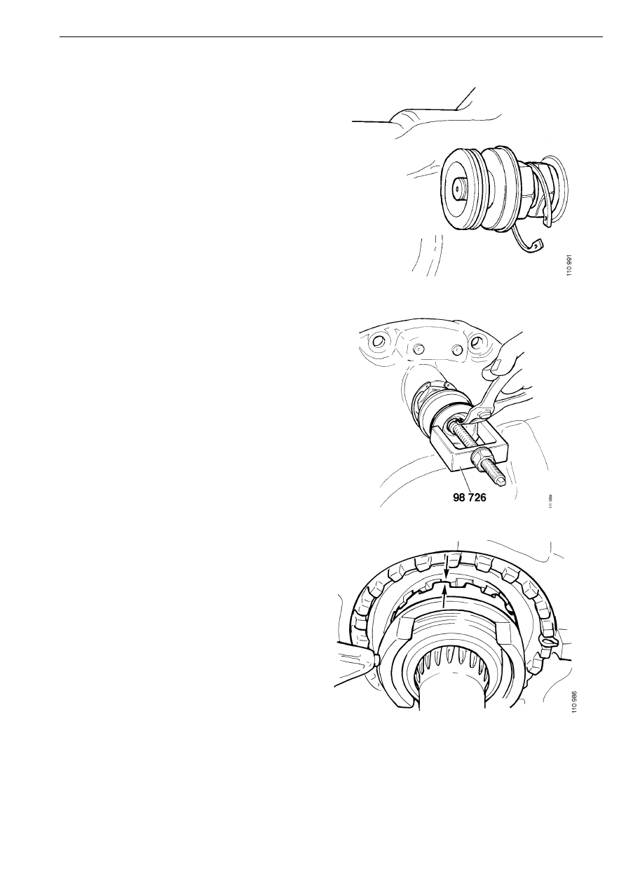
9
Mount the retaining ring 34 onto the screw
for the assembly tool 98 726 and screw the
tool to the pull rod. Pull the rod forward
enough to hook on the retaining ring.
Remove the tool.
10 Raise the rear left wheel so that the
differential gears can be rotated. Screw out
the bottom section at the same time until the
top of the gear teeth scrape against each
other. Then screw in the bottom section one
turn and tighten the lock nut.
If the axle gear has been removed, insert a
drive shaft that has been cut off into the
differential so that the differential gears can
be turned when adjusting the tooth pitch.
Spot repairs