Seat Toledo (2019 year). Manual in english - page 9
 

  Index      Manuals     Seat Toledo (2019 year). Manual in english


Search            copyright infringement  


Content      ..     7      8      9      10     ..


Seat Toledo (2019 year). Manual in english - page 9


Transport and practical equipment

5 V power sockets (USB)*

The 5 V power sockets are located at the rear
of the console, between the front seats, fac-
ing the rear seat occupants.

They are USB ports to which only devices and
accessories that use this type of charging
can be connected.

They are not intended for file playback.

The maximum power of these sockets is 2 A.

WARNING

Improper use of the sockets or electrical

appliances can cause a fire and lead to
burns and other serious injuries.

Never leave children unsupervised in the

vehicle. The 12 V power socket is also func-
tional when the ignition is switched off and
the key is removed.

Should the connected appliance over-

heat, immediately switch it off and discon-
nect it from the socket.

CAUTION

The 12 V power socket can only be used

to power appliances with a power rating of
up to 120 watts.

Never exceed the maximum permitted

power, as this could cause damage to the
vehicle electrical installation.

With the engine switched off, however,

the vehicle battery will drain. Risk of dis-
charging the battery!

Only use suitable plugs so as not to dam-

age the power socket.

Only use appliances that have been tes-

ted for electromagnetic compatibility in
compliance with current regulations.

Before switching the ignition on or off, un-

plug the appliances from the power socket
to protect them from any damage caused
by fluctuations in voltage.

Follow the instructions for use of connec-

ted appliances!

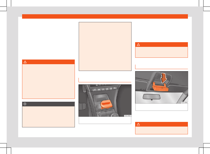
Multimedia compartment

Fig. 155 

Front centre console: multimedia

compartment.

The multimedia compartment is in the stor-
age compartment of the front centre console

››› 

Fig. 155

.

The compartment can be used to hold mo-
bile phones, mp3 players or similar devices.

WARNING

Never use the multimedia compartment as
an ashtray or to store flammable materials.
Risk of fire!

Storage compartment for glasses*

Fig. 156 

Close-up of roof panel: storage com-

partment for glasses.

Press the compartment lid and it will drop
down 

››› 

Fig. 156

.

WARNING

This compartment must only remain open
when removing or replacing glasses.

»

139

Operation

CAUTION

Do not place heat-sensitive objects in the

compartment as they could be damaged.

The side compartment supports a maxi-

mum load of 0.25 kg.

Coat hooks*

The coat hooks are located on the B-pillars
and on the handles on the interior lining
above each rear door.

WARNING

Make sure that any items of clothing

hanging from the coat hooks do not ob-
struct your view to the rear.

Only use the coat hooks for light items of

clothing and make sure that there are no
heavy or sharp objects in the pockets.

Do not use clothes hangers to hang up

the clothing, as this could interfere with the
function of the head-protection airbags.

CAUTION

The side hooks support a maximum load of
2 kg.

Compartments in the centre con-
sole

Fig. 157 

Centre console: storage compart-

ment.

Open storage compartment in centre con-
sole 

››› 

Fig. 157

.

Storage compartment in front door

Fig. 158 

Storage compartment in door trim.

There is a bottle carrier in part 

B


››› 

Fig. 158

of the storage compartment in the front door.

WARNING

Only use part 

A


››› 

Fig. 158

 of the compart-

ment in the front door to store objects that
do not protrude from it so as not obstruct
the deployment area of the side airbags.

Storage compartment in the lug-
gage compartment*

Fig. 159 

Boot: storage compartment.

The lid from the side storage compartment
can be removed to increase the size of the
boot.

Hold onto the top of the lid and pull it out in
the direction indicated by the arrow

››› 

Fig. 159

.

140

Transport and practical equipment

CAUTION

The compartments are designed to hold

small objects with a total weight of 1.5 kg.

Make sure you do not damage the stor-

age compartment or the boot trim when
using the compartment.

Storing objects

Loading the luggage compartment

All luggage and other loose objects must be
safely secured in the luggage compartment.

Unsecured objects which shift back and forth
could impair the driving safety or driving
characteristics of the vehicle by shifting the
centre of gravity.

Distribute the load evenly in the luggage
compartment.

Place heavy objects as far forward as pos-
sible in the luggage compartment.

Place the heavy objects first.

Secure heavy objects to the fitted fastening
rings 

››› 

page 141

.

WARNING

Loose luggage and other objects in the

luggage compartment could cause serious
injuries.

Always stow objects in the luggage com-

partment and secure them on the fastening
rings.

Use suitable straps to secure heavy ob-

jects.

During sudden manoeuvres or accidents,

loose objects can be thrown forward, injur-
ing vehicle occupants or passers-by. This
increased risk of injury will be further in-
creased if a loose object is struck by an in-
flating airbag. If this happens, objects may
shoot outward like a missile. Risk of fatal in-
jury.

Please note that the centre of gravity

may shift when transporting heavy objects;
this may affect vehicle handling and lead
to an accident. Therefore, it is essential to
adjust your speed and driving style ac-
cordingly, to avoid accidents.

Never exceed the allowed axle weights or

allowed maximum weight. If said weights
are exceeded, the driving characteristics of
the vehicle may change, leading to acci-
dents, injuries and damage to the vehicle.

Never leave your vehicle unattended, es-

pecially when the rear lid is open. Children
could climb into the luggage compartment,
closing the door behind them; they will be
trapped and run the risk of death.

Never allow children to play in or around

the vehicle. Close and lock all the doors
and the rear lid when you leave the vehicle.
Before you lock the vehicle, make sure that

there are no adults or children in the vehi-
cle.

Note

Air circulation in the vehicle helps reduce

fogging of the windows. Used air escapes
through ventilation slits in the side trim of
the luggage compartment. Ensure that the
ventilation slots are never covered.

Straps for securing the load to the fas-

tening rings are commercially available
from accessory shops.

Fastening rings*

There can be four fastening rings in the lug-
gage compartment for fastening luggage
and other objects.

Always use suitable and undamaged straps
to secure luggage and other objects to the
fastening rings 

››› 

 in Loading the lug-

gage compartment on page 141

.

Pull up the fastening rings to attach the
straps.

During a collision or an accident, even small
and light objects can build up so much ener-
gy that they can cause very severe injuries.
The amount of kinetic “energy” depends on
the speed of the vehicle and the weight of the

»

141

Operation

object. The most significant factor, however,
is the speed of the vehicle.

Example: An object weighing 4.5 kg is lying
unsecured in the vehicle. During a frontal col-
lision at a speed of 50 km/h (31 mph), this ob-
ject generates a force corresponding to 20
times its weight. That means that the effective
weight of the object increases to approxi-
mately 90 kg. You can imagine the severity of
the injuries which might be sustained if this
“object” strikes an occupant as it flies through
the interior of the vehicle. This increased risk
of injury will be further increased if a loose
object is struck by an inflating airbag.

WARNING

If pieces of baggage or other objects are

secured to the fastening rings with inappro-
priate or damaged retaining cords, injuries
could result in the event of braking ma-
noeuvres or accidents.

Never secure a child seat on the fasten-

ing rings.

Luggage compartment

Introduction

Please observe the following points to ensure
the vehicle handles well at all times:

Distribute the load as evenly as possible.

Place heavy objects as far forward in the
luggage compartment as possible.

Secure luggage using the fastening rings or
retaining net 

››› 

page 143

.

During an accident, even small and light ob-
jects can have so much kinetic energy that
they can cause very severe injuries. The
amount of kinetic energy depends on the
speed of the vehicle and the weight of the
object. However, the speed of the vehicle is
the most important factor.

Example: an unsecured object weighing 4.5
kg produces energy corresponding to 20
times its weight in a frontal collision at 50
km/h (31 mph). This means that its weight
reaches around 90 kg. You can imagine the
severity of the injuries that might be sustained
if this “projectile” strikes an occupant as it
flies through the vehicle interior.

WARNING

Store objects in the luggage compart-

ment and secure to the fastening points.

In an accident or sudden manoeuvre,

loose objects in the interior can be flung
forward and possibly injure vehicle occu-
pants or others. This risk is even greater if
the flying objects hit a triggering airbag. In
this case, any rebounding objects could in-
jure vehicle occupants. Risk of fatal inju-
ries!

Take into account that transporting

heavy objects changes the centre of gravi-
ty that could also cause changes in vehicle
handling. Risk of accident! Therefore, al-
ways adjust your speed and driving style to
suit these circumstances.

Securing the load to the rings using un-

suitable or damaged straps could lead to
injuries in the event of an accident or sud-
den braking manoeuvre. Secure suitable
straps safely to the rings to ensure this
does not happen.

Position the load so it cannot move for-

ward during a sudden braking manoeuvre.
Risk of injuries!

If transporting sharp or dangerous ob-

jects in the space provided when the rear
seats are folded, ensure the safety of the
occupant of the remaining rear seat

››› 

page 60

.

If the rear seat located alongside a fol-

ded seat is occupied, ensure safety, for ex-
ample, by placing the load so that it stops
the seat from folding backward in the event
of being hit from behind.

Never drive with the rear lid open or half-

closed, exhaust gases may penetrate into
the interior of the vehicle. Danger of poi-
soning!

Never exceed the allowed axle loads or

allowed maximum weight. Risk of accident!

Never transport passengers in the lug-

gage compartment!

142

Transport and practical equipment

CAUTION

Make sure sharp objects stored in the boot
cannot not damage the rear window heat-
ing filaments.

Note

Tyre pressure must be adapted to suit the
load 

››› 

page 256, Service life of tyres

.

Category N1 vehicles

Category N1 vehicles with no protection grille
must use a retaining set compliant with
Standard EN 12195 (1 – 4) to secure the load.

Retaining elements*

Fig. 160 

Boot: retaining elements.

The following retaining elements are fitted in
the boot 

››› 

Fig. 160

:

Rings to secure the load and the retaining
nets.
Rings used solely for the retaining nets.

CAUTION

The rings support a maximum load of 3.5 kN
(350 kg).

Note

The front ring 

B

 is below the folding back-

rest of the rear seats 

››› 

Fig. 160

.

Hook*

Fig. 161 

Boot: hook.

There are hooks on both sides of the boot to
secure light items of luggage such as bags,
etc. 

››› 

Fig. 161

A

B

CAUTION

The side hooks support a maximum load of
7.5 kg.

Retaining nets*

Fig. 162 

Retaining nets.

Fig. 163 

Retaining nets.

Example of securing retaining nets 

››› 

Fig. 162

and 

››› 

Fig. 163

.

»

143

Operation

Sideways bag
Ground net
Lengthways bag

WARNING

Do not exceed the maximum load that the
nets can support. Heavy objects cannot be
safely secured. Risk of injury!

CAUTION

The retaining nets support a maximum

load of 1.5 kg.

Do not place any item with sharp edges

in the net. Risk of damaging the net!

Luggage compartment shelf

Fig. 164 

Remove the shelf.

A

B

C

Fig. 165 

Remove the shelf.

The shelf can be removed if a large load is to
be transported.

Removing the shelf

Remove the straps from the shelf 

1

››› 

Fig. 164

.

Remove the shelf from its housing 

2

 by

knocking it gently from underneath be-
tween the supports.

Fitting the shelf

Place the shelf on the side supports on the
trim.

Adjust the shelf supports 

3


››› 

Fig. 165

 to fit

the supports 

2

 in the trim.

Fit into place by knocking the top of the
shelf gently between the supports.

Attach the straps 

1

 to the tray.

WARNING

Do not place objects on the rear shelf that
could endanger the vehicle occupants in
case of a sudden braking manoeuvre or an
accident.

CAUTION

The rear shelf supports a maximum load

of 1 kg.

If handled incorrectly, the rear shelf

could bend when closing the rear lid, and
become damaged or damage the trim. Fol-
low the instructions below:

The shelf supports 

3


››› 

Fig. 165

 must

be securely in place in the trim sup-
ports 

2

.

The size of the load must not exceed
the height of the shelf.

When open, the shelf must not be bent
against the shelf seal.

There must be no objects in the space
between the open shelf and the back-
rest of the rear seat.

Note

The shelf will lift when the rear lid is
opened.

144

Transport and practical equipment

Roof rack*

Introduction

WARNING

The load on the roof carrier must be

properly secured. Risk of accident!

Always secure the load using retaining

straps that are in good condition.

Distribute the load evenly.

When transporting heavy or large ob-

jects on the roof, any change in normal ve-
hicle behaviour due to a change in the cen-
tre of gravity or increased wind resistance
must be taken into account. Risk of acci-
dent! For this reason, speed and driving
style must be adjusted for the situation.

Avoid sudden manoeuvres and braking.

Adjust your driving style to suit visibility,

the weather and road and traffic condi-
tions.

Never exceed the allowed axle loads or

allowed maximum weight. Risk of accident!

CAUTION

Only use SEAT-authorised roof carriers.

Where roof carriers from other systems

are used or where they are not fitted prop-
erly, any damage caused to the vehicle will
not be covered by the warranty. Therefore,

carefully follow the Instruction Manual for
installation of the roof carrier.

Remember that the rear lid must not hit

the roof load.

The total height of the vehicle increases

according to the roof load. Compare the
height of the vehicle with the heights of
bridges or other underpasses, for example,
the height of the garage door.

Do not forget to remove the roof carrier

before entering an automatic carwash.

Take into account that the load must not

damage the aerial located on the roof.

For the sake of the environment

If aerodynamic resistance increases, fuel
consumption will also increase.

Attachment points

Fig. 166 

Basic roof carrier attachment points.

Location of the basic roof carrier attachment
points 

››› 

Fig. 166

:

Rear attachment points
Front attachment points

Install and remove following the instructions
given.

»

A

B

145

Operation

CAUTION

Follow the instructions given in the manual.

Roof load

The maximum permissible roof load (includ-
ing the support system) of 

75 kg

 and the total

authorised weight of the vehicle must not be
exceeded.

It will not be possible to carry the full maxi-
mum load if the roof carrier you are using is
rated for a load which is less than this figure.
In this case, you can only load the roof carrier
to the maximum load permitted in your instal-
lation manual.

Air conditioning

Heating and air conditioning

General notes

The power of the heating depends on the
temperature of the coolant. Therefore, maxi-
mum power is only obtained when the engine
has reached operating temperature.

The temperature and humidity of the air in-
side the vehicle decrease when the cooling
system is turned on. This therefore increases
the comfort of all vehicle occupants when
outside temperatures and humidity are high. It
also helps prevent the windows from misting
over during cold periods of the year.

The air recirculation system can be switched
on temporarily to increase the cooling effect.

Keep the air intake slots in front of the wind-
screen clear of ice, snow or leaves to ensure
unimpaired heating and cooling.

When the air conditioning is on, 

condensa-

tion

 can drip from the evaporator in the air

cooling system and form a pool underneath
the vehicle. This is normal and does not indi-
cate a leak!

WARNING

All windows must be clear of ice, snow

and condensation for driving safety. There-

fore, make sure you familiarise yourself
with the correct use of heating and ventila-
tion, window demisting and defrosting and
cooling.

Never use the air recirculation system for

too long, as it prevents fresh air from enter-
ing the vehicle and used air can cause
tiredness, reduce your attention span and
cause the windows to mist over. This in-
creases the risk of an accident. Switch off
the air recirculation system as soon as the
windows begin to mist over.

WARNING

Do not switch off Climatronic for longer
than necessary.

Switch Climatronic back on as soon as

the windows begin to mist over.

Note

Used air escapes through ventilation

slots in the rear of the luggage compart-
ment.

Smoking is not recommended while the

air recirculation system is in use, as the
smoke drawn from the interior of the vehi-
cle settles in the evaporator of the air con-
ditioning system. This causes a persistent,
unpleasant smell while the system is run-
ning that is time-consuming and expensive
(evaporator replacement) to eliminate.

146

Air conditioning

To guarantee proper operation, never

cover the air outlets in the luggage com-
partment.

Economic use of the air-condition-
ing system

When the air conditioning is switched on, the
compressor consumes engine power and has
influence on fuel consumption.

If the vehicle interior has overheated due to
excessive solar radiation, it is best to open the
windows or doors to allow the hot air to es-
cape.

While in motion, the air conditioning should
not be switched on if the windows are open.

If the interior temperature can be reached
without switching on the air conditioning, the
fresh air mode should be used.

For the sake of the environment

Saving fuel reduces emissions.

Faults

If the air conditioning does not work at out-
side temperatures above +5°C (+41°F) then

the system is faulty. This may be due to one
of the following reasons:

One of the fuses has blown. Check the fuse

and replace if necessary 

››› 

page 83

.

The air conditioning compressor has

switched off temporarily because of in-
creased engine coolant temperature

››› 

page 101

.

If you cannot repair the fault yourself or
where cooling power continues to drop,
switch off the system. Contact a specialised
service.

Air vents

Fig. 167 

Air vents.

»

147

Operation

Opening air vents 3 and 4

Turn the vertical circular control upwards.

Closing air vents 3 and 4

Turn the vertical circular control down-
wards.

Changing the direction of air delivery from
air vents 3 and 4

The air circulation height can be varied by
changing the position of the sliding adjuster
upwards or downwards 

››› 

Fig. 167

.

The air circulation direction can be varied
by changing the position of the sliding ad-
juster to the right or to the left.

The flow of air from the vents is controlled us-
ing control 

C


››› 

Fig. 168

. Vents 

3


››› 

Fig. 167

and 

4

 can be opened and closed individual-

ly.

Depending on the position of the adjusters
and on the weather, open vents can provide
air which is either heated, unheated or
cooled.

Heating and fresh air

Operation

Fig. 168 

Heating: controls.

Read the additional information carefully

››› 

page 39

Temperature selection

Turn rotary control 

A


››› 

Fig. 168

 clockwise

to increase the temperature.

Turn rotary control 

A

 anti-clockwise to re-

duce the temperature.

Blower selection

Turn rotary control 

B


››› 

Fig. 168

 to position

1 to 4 to switch the blower on.

Turn rotary control 

B

 to position 0 to switch

the blower off.

Press button 

1


››› 

 in Air recirculation

 on page 149

 to close the fresh air vent.

Air distribution selection

Turn rotary control 

C


››› 

Fig. 168

 to select

the air vents 

››› 

page 147, Air vents

 you

wish to activate.

All controls, except control 

B


››› 

Fig. 168

,

can be set to any intermediate position.

Leave the blower activated at all times to
prevent the windows from misting over.

Note

If the system is set so that all of the air is
used to defrost the windows, no air is sup-
plied to the footwell area. This could limit
heating comfort.

Air recirculation 

Air recirculation prevents unpleasant smells,
e.g. when passing through a tunnel or in
queuing traffic, from entering the interior.

If the rotary switch 

C


››› 

Fig. 168

 is in the

thaw position, the recirculation flap will al-
ways be open (button light off).

If the rotary switch 

C

 is switched from any

position to the thaw position, recirculation will
be automatically deactivated.

148

Air conditioning

Connecting the recirculation

In any position of rotary switch 

C

 except

thaw:

Press button 

1


››› 

Fig. 168

, the switch's

lamp will light up, indicating that air recircula-
tion inside the vehicle has been activated.

Disconnecting the recirculation

In any position of rotary switch 

C

 except

thaw:

Press button 

1

 again and the button's

lamp will go off, indicating that air recircula-
tion from the outside has been activated.

In the thaw position of rotary switch 

C

, the

entry of air into the vehicle interior is always
from the outside.

WARNING

Read and observe the safety warnings 

››› 

in General notes on page 146

.

Air conditioning (manual)*

Manual operation

Fig. 169 

Air conditioning: controls.

Read the additional information carefully

››› 

page 38

The air cooling system only works if button




2


››› 

Fig. 169

 is pressed and under the

following conditions:

The engine is running,

The outside temperature is above +2°C

(+36°F),

The blower control is in position 1–4.

When the cooling system is on and under
certain conditions, air can be blown from the
vents at a temperature of approximately
+5°C (+41°F). In the event of prolonged, irreg-
ular distribution of the air flow from the outlets
and significant differences in temperature,

e.g. on leaving the vehicle, sensitive people
may catch cold.

Temperature selection

Turn rotary control 

A


››› 

Fig. 169

 clockwise

to increase the temperature.

Turn rotary control 

A

 anti-clockwise to re-

duce the temperature.

Blower selection

Turn rotary control 

B


››› 

Fig. 169

 to position

1 to 4 to switch the blower on.

Turn rotary control 

B

 to position 0 to switch

the blower off.

Press button 


1


››› 

page 150, Air recir-

culation

 to close the fresh air vent.

Air distribution selection

Turn rotary control 

C


››› 

Fig. 169

 to select

the air vents 

››› 

page 147

 you wish to acti-

vate.

Switching cooling on and off

Press button 




2


››› 

Fig. 169

 and the

lamp in the button will illuminate.

Press button 




2

 again and the light in

the button will switch off.

»

149

Operation

Coldest setting

On turning the control 

A

 to the coldest set-

ting (blue indicator), buttons 

1


 and 

2



 light up.

The recirculation function is activated auto-

matically in order to cool faster.

Note

A visit to the specialised service once a

year is recommended to clean the air con-
ditioning system.

If the air distribution is directed towards

the windows, all, of the heating power is
used to defrost the windscreen. No warm
air is directed to the footwell area. This
could limit heating comfort.

The AC button lamp 



 will illuminate af-

ter the system has been switched on, even
if not all of the cooling system's operating
conditions are met. Cooling is indicated as

available once all of the conditions are met

››› 

page 149, Manual operation

.

Air recirculation

Air recirculation prevents unpleasant smells,
e.g. when passing through a tunnel or in
queuing traffic, from entering the interior.

If the rotary switch 

C


››› 

Fig. 169

 is in the

thaw position, the recirculation flap will al-
ways be open (button light off).

If the rotary switch 

C

 is switched from any

position to the thaw position, recirculation will
be automatically deactivated.

Connecting the recirculation

In any position of rotary switch 

C

 except

thaw:

Press button 

1


››› 

Fig. 169

, the switch's

lamp will light up, indicating that air recircula-
tion inside the vehicle has been activated.

Disconnecting the recirculation

In any position of rotary switch 

C

 except

thaw:

Press button 

1

 again and the button's

lamp will go off, indicating that air recircula-
tion from the outside has been activated.

In the thaw position of rotary switch 

C

, the

entry of air into the vehicle interior is always
from the outside.

WARNING

Read and observe the safety warnings 

››› 

in General notes on page 146

.

150

Air conditioning

Climatronic* (automatic air conditioning)

General notes

Fig. 170 

Climatronic: controls.

Read the additional information carefully

››› 

page 37

Climatronic automatically maintains a com-
fortable temperature. To do so, it automati-
cally regulates the supplied air temperature
and the blower and air distribution levels. The
system also allows for the effect of sunlight,
so there is no need for manual adjustment. It
also has a humidity sensor that helps to auto-
matically demist the windscreen.

Automatic operations


››› 

page 152

 guaran-

tee maximum comfort any time of year.

Climatronic description

Cooling only works if the following conditions
are met:

The engine is running

the outside temperature is above +2°C

(+36°F);




››› 

Fig. 170 

18

 turned on.

Starting the Climatronic

The corresponding function will be switched
on when a button is pressed, turning on the
air conditioning if it was switched off, with the
exception of button 

17

 (recirculation).

Switching off the Climatronic

Turn control 

10

 to the left until the segments

of column 

9


››› 

Fig. 170

 switch off.

After 

1 second

 has elapsed, turn the control

again to switch off the display.

In order to ensure engines subject to heavy
loads are cooled, the air conditioning com-
pressor is switched off in the event of high
coolant temperatures.

Recommended setting for all seasons of
the year

Set the required temperature. We recom-

mend +22°C (+72°F).

»

151

Operation

Press the button 




13


››› 

Fig. 170

.

Adjust vents 

3

 and 

4


››› 

page 147

 so that

the air flow is directed slightly upwards.

Change between degrees Centigrade and
degrees Fahrenheit

Keep the 



 and 




››› 

Fig. 170

 buttons held

down for 

2 seconds

 at the same time. The

data is displayed on the screen in the units
required.

Note

A visit to the specialised service once a

year is recommended to clean the Clima-
tronic system.

The interior temperature sensor 

11

››› 

Fig. 170

 is at the bottom. Do not cover it

with stickers or the like, as this could have a
negative effect on Climatronic operations.

Automatic mode

Automatic mode is used to maintain a con-
stant temperature and demist the windows
inside the vehicle.

Switching on automatic mode

Set a interior temperature between +16°C

(+64°F) and +29°C (+84°F).

Adjust vents 

3


››› 

page 147

 and 

4

 so that

the air flow is directed slightly upwards.

Press the button 




13


››› 

Fig. 170

, and

AUTO

 is displayed on the screen.

Automatic mode is switched off by pressing
the air distribution buttons or increasing or
decreasing the blower speed. However, the
temperature remains regulated.

Adjusting the temperature

When you switch on the ignition, control 

1

››› 

Fig. 170

 can be used to set the required in-

terior temperature.

It is possible to select interior temperatures
from +16°C (+64°F) to +29°C (+84°F). In this
range the temperature is regulated automati-
cally. If a temperature below +16°C (+64°F) is
selected, “LO” is displayed on the screen. If a
temperature above +29°C (+84°F) is selec-
ted, “HI” is displayed on the screen. At both
extremes, Climatronic works at maximum
cooling or heating power, respectively. The
temperature is not regulated.

In the event of prolonged, irregular distribu-
tion of the air flow from the outlets (particu-
larly the footwells) and significant differences
in temperature, e.g. on leaving the vehicle,
sensitive people may catch cold.

Air recirculation

Air recirculation prevents unpleasant smells,
e.g. when passing through a tunnel or in
queuing traffic, from entering the interior.

Switching on air recirculation mode

Press the button 


17


››› 

Fig. 170

 and the

 symbol is displayed on the screen.

Switching off air recirculation mode

Press the button 


17


››› 

Fig. 170

 and the

 symbol disappears from the screen.

WARNING

Read and observe the safety warnings 

››› 

in General notes on page 146

.

Note

If air recirculation mode remains on for 15
minutes, the 

 symbol will start to flash on

the screen to indicate prolonged air recir-
culation. If air recirculation is not switched
off, the symbol will continue to flash for
about 5 minutes.

Blower selection

Climatronic automatically regulates blower
speed according to the interior temperature.

152

Air conditioning

It is possible, however, to set the blower
speed to suit requirements.

Turn control 

10


››› 

Fig. 170

 counter-clock-

wise (to lower the speed) or clockwise (to in-
crease the speed).

Climatronic will switch off when the blower
switches off.

WARNING

Read and observe the safety warnings 

››› 

in General notes on page 146

.

Windscreen defrost

Switching on windscreen defrosting

Press the button 




12


››› 

Fig. 170

.

Switching off windscreen defrosting

Press the button 




12


››› 

Fig. 170

 sever-

al times or press the 



 button.

The temperature is regulated automatically.
The air output is increased from vents 

1

››› 

page 147

 and 

2

.

153

Infotainment System

Infotainment System

Introduction

Safety warnings

Infotainment system safety in-
structions

Travelling on today's roads requires the driv-
er's full attention at all times.

Only operate the infotainment system and its
various functions when the traffic situation
really permits this.

WARNING

Before starting the trip, you should famili-

arise yourself with the different infotain-
ment system functions.

High audio volume may represent a dan-

ger to you and to others.

Adjust the volume in a way that you can

distinguish surrounding noise, for example,
horns and sirens, etc.

Changes to the Infotainment system set-

tings should be made when the car is stop-
ped, or by a passenger.

WARNING

Distracting the driver in any way can lead
to an accident and cause injuries. Operat-
ing the Infotainment system can distract
your attention from the traffic.

Always drive carefully and responsibly.

Select volume settings that allow you to

easily hear signals from outside the vehicle
at all times (e.g. emergency services sirens
and horns).

Hearing may be impaired if using too high

a volume setting, even if only for short peri-
ods of time.

WARNING

The volume level may suddenly change
when you switch audio source or connect a
new audio source.

Lower the base volume before connect-

ing or switching audio sources.

WARNING

The driving recommendations and traffic
indications shown on the navigation system
may differ from the current traffic situation.

Traffic signs and traffic regulations have

priority over the recommendations and dis-
plays provided by the navigation system.

Adjust your vehicle speed and driving

style to suit visibility, weather, road and
traffic conditions.

WARNING

Connecting, inserting or removing a data
medium while driving can distract your at-
tention from the traffic and cause an acci-
dent.

WARNING

Connecting leads for external devices may
obstruct the driver.

Arrange the connecting leads so that

they do not obstruct the driver.

WARNING

External devices that are loose or not prop-
erly secured could move around the pas-
senger compartment during a sudden driv-
ing or braking manoeuvre or an accident
and cause damage or injury.

Never place or fit external devices to the

doors, windscreen, steering wheel, dash
panel, the backs of the seats, on top of or
near the area marked “AIRBAG” or between
these areas and the occupants. External
devices can cause serious injury in an acci-
dent, especially when the airbags inflate.

WARNING

The armrest may obstruct the driver's arm
movements, which could cause an acci-
dent and severe injuries.

154


Content      ..     7      8      9      10     ..