Seat Toledo (2019 year). Manual in english - page 3
 

  Index      Manuals     Seat Toledo (2019 year). Manual in english


Search            copyright infringement  


Content      ..     1      2      3      4      ..


Seat Toledo (2019 year). Manual in english - page 3


The essentials

Coolant

Fig. 52 

Engine compartment: coolant expan-

sion tank cap.

The coolant tank is located in the engine
compartment 

››› 

page 246

.

When the engine is cold, replace the coolant
when the level is below 



.

Coolant specifications

The engine cooling system is supplied from
the factory with a specially treated mixture of
water and at least 40 % of the additive 

G13

(TL-VW 774 J), purple. This mixture gives the
necessary frost protection down to -25°C
(-13°F) and protects the light alloy parts of
the engine cooling system against corrosion.
It also prevents scaling and considerably rai-
ses the boiling point of the coolant.

To protect the cooling system, the percent-
age of additive must always be at least 40 %,

even in warm climates where anti-freeze pro-
tection is not required.

If for weather reasons further protection is
necessary, the proportion of additive may be
increased, but only up to 60 %; otherwise an-
tifreeze protection will diminish and this will
worsen cooling.

When the coolant is topped up, use a mixture
of 

distilled water

 and at least 40 % of the

G13 or G12 plus-plus (TL-VW 774 G) additive
(both are purple) to obtain optimal anti-cor-
rosion protection. The mixture of G13 with G12
plus (TL-VW 774 F), G12 (red) or G11 (green-
blue) engine coolants will significantly re-
duce anti-corrosion protection and should
therefore be avoided.

››› 

 in Topping up the coolant level

on page 250

››› 

page 248

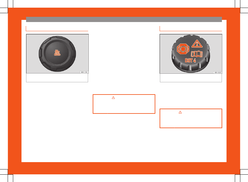
Brake fluid

Fig. 53 

Engine compartment: brake fluid reser-

voir cap.

The brake fluid reservoir is located in the en-
gine compartment 

››› 

page 246

.

The level should be between the 



 and 



marks. If it is below 



, please visit a Technical

Service.

››› 

 in Checking brake fluid level on

page 250

››› 

page 250

43

The essentials

Windscreen washer

Fig. 54 

In the engine compartment: cap of the

windscreen washer tank.

The windscreen washer reservoir is located in
the engine compartment 

››› 

page 246

.

To top up, mix water with a product recom-
mended by SEAT.

In cold temperatures, add anti-freeze.

››› 

page 251

Battery

The battery is located in the engine compart-
ment 

››› 

page 246

. It does not require

maintenance. It is checked as part of the In-
spection Service.

››› 

 in Introduction on page 252

››› 

page 251

44

The essentials

Emergencies

Fuses

Fuse location

Fig. 55 

On the dashboard on the driver side:

lid of the fuse box.

Fig. 56 

In the engine compartment: lid of the

fuse box.

Underneath the instrument panel

Carefully tilt the cover in the direction indi-

cated by the arrow and remove it 

››› 

Fig. 55

.

After changing the fuse, replace the cover

on the dash panel in the direction opposite
that is indicated by the arrow so that the cov-
er tabs fit into the slots on the dash panel.
Subsequently, press down on the cover to
close.

In the engine compartment

Press the locking tabs to release the fuse box
cover 

››› 

Fig. 56

.

Identifying fuses situated below the dash
panel by colours

Colour

Amp rating

Black

1

Purple

3

Light brown

5

Brown

7.5

Red

10

Blue

15

Yellow

20

White or transparent

25

Green

30

Orange

40

››› 

 in Introduction on page 83

››› 

page 83

Replacing a blown fuse

Fig. 57 

Image of a blown fuse.

Preparation

Switch off the ignition, lights and all electri-

cal equipment.

Open the corresponding fuse box

››› 

page 84

.

Identifying a blown fuse

A fuse is blown if its metal strip is ruptured

››› 

Fig. 57

.

Point a lamp at the fuse to see if it has blown.

»

45

The essentials

To replace a fuse

Remove the fuse.

Replace the blown fuse by one with an

identical

 amperage rating (same colour and

markings) and 

identical

 size.

Replace the cover again or close the fuse

box lid.

Bulbs

Bulbs (12 V)

Full-LED headlights are designed to last the
lifetime of the car and cannot be replaced. If
the headlight becomes damaged, go to a
specialised workshop.

Below, the light source used for all functions is
broken down.

Halogen headlights.

Type

Daytime running light/side
light

P21W SLL

Dipped beam headlights

H7 LL

Main beam headlights

H7 LL

Turn signal

PY21W

Full-LED main head-

lights

Type

No bulbs may be replaced. All functions are with

LEDs

Front fog light

Type

Fog/cornering lights*

H8

Rear bulb light

Type

Brake light/tail light

P21/5W

Side lights

P21/5W (side panel)

R5W (rear lid)

Turn signal

PY21W

Retro fog light

P21W

Reverse lights

P21W

LED rear lights

Type

Turn signal

PY21W

Retro fog light

P21W

Reverse lights

P21W

The remaining functions work with LEDs

››› 

page 86

Action in the event of a punc-
ture

What to do first

Park the vehicle on a horizontal surface and

in a safe place as far away from traffic as
possible.

Apply the handbrake.

Switch on the hazard warning lights.

Manual transmission:

 select the 1st gear.

Automatic transmission:

 Move the selector

lever to position 

P

.

If you are towing a trailer, unhitch it from

your vehicle.

Have the vehicle tool kit* 

››› 

page 78

and the spare wheel 

››› 

page 259

 ready.

Observe the applicable legislation for each

country (reflective vest, warning triangles,
etc.).

All occupants should leave the vehicle and

wait in a safe place (for instance behind the
roadside crash barrier).

WARNING

Always observe the above steps and pro-

tect yourself and other road users.

If you change the wheel on a slope, block

the wheel on the opposite side of the car

46

The essentials

with a stone or similar to prevent the vehi-
cle from moving.

Repairing a tyre with the anti-punc-
ture kit

Fig. 58 

Standard display: contents of the anti-

puncture kit.

The anti-puncture kit is located under the
floor panel in the luggage compartment.

Sealing the tyre

Unscrew the tyre valve cap and insert. Use

the 

››› 

Fig. 58


1

 tool to remove the insert.

Place it on a clean surface.

Shake the tyre sealant bottle vigorously

››› 

Fig. 58


10

.

Screw the inflator tube 

››› 

Fig. 58


3

 into

the sealant bottle. The bottle's seal will break
automatically.

Remove the lid from the filling tube

››› 

Fig. 58


3

 and screw the open end of the

tube into the tyre valve.

With the tyre sealant bottle upside down, fill

the tyre with the contents of the sealant bot-
tle.

Remove the bottle from the valve.

Place the insert back into the tyre valve us-

ing the tool 

››› 

Fig. 58


1

.

Inflating the tyre

Screw the compressor tyre inflator tube

››› 

Fig. 58


5

 into the tyre valve.

Check that the air bleed screw is closed

››› 

Fig. 58


7

.

Start the engine and leave it running.

Insert the connector 

››› 

Fig. 58


9

 into the

vehicle's 12-volt socket 

››› 

page 138

.

Turn the air compressor on with the

ON/OFF switch 

››› 

Fig. 58


8

.

Keep the air compressor running until it rea-

ches 2.0 to 2.5 bar (29-36 psi/200-250 kPa).

A maximum of 8 minutes

.

Disconnect the air compressor.

If it does not reach the pressure indicated,

unscrew the tyre inflator tube from the valve.

Move the vehicle 10m so that the sealant is

distributed throughout the tyre.

Screw the compressor tyre inflator into the

valve.

Repeat the inflation process.

If the indicated pressure still cannot be

reached, the tyre is too badly damaged. Stop
and request assistance from an authorised
technician.

Disconnect the air compressor. Unscrew

the tyre inflator tube from the tyre valve.

When the tyre pressure is between 2.5 and

2.0 bars, continue driving without exceeding
80 km/h (50 mph).

Attach the sticker 

››› 

Fig. 58


2

 to the in-

strument cluster, within the driver's visual
field.

Check the pressure again after 10 minutes

››› 

page 81

.

››› 

 in TMS Anti-puncture kit (Tyre

Mobility System)* on page 80

››› 

page 79

47

The essentials

Changing a wheel

Vehicle tool kit*

Fig. 59 

Vehicle tool kit.

The vehicle tool kit and the jack are stored in
a box on the spare wheel or in the spare
wheel well. There is also enough space for
the towing bracket ball coupling. The box is
strapped to the spare wheel with tape.

The vehicle tool kit includes the following
parts (depending on equipment):

Screwdriver
Adapter for anti-theft wheel bolts
Towline anchorage
Wire hook for removing hub caps
Jack
Box spanner for wheel bolts

1

2

3

4

5

6

Clip for wheel bolt cover
Spare set of bulbs

Before stowing the jack again, screw down
the arm as far as it will go.

››› 

 in What to do first on page 46

››› 

page 78

Wheel cover

Fig. 60 

Remove the wheel cover.

Removing

Place the hook from the vehicle tool kit* on

the reinforced edge of the wheel trim.

Insert the box spanner through the hook,

supporting it on the tyre and remove the
wheel trim.

7

8

Fitting

Press the wheel trim onto the wheel at the

cut out designed for the valve.

Press the wheel trim on both sides in the di-

rection of the valve so that it fits correctly in
place around all the perimeter.

CAUTION

Press down by hand, do not hit the wheel

trim! Knocking it sharply, particularly at
points where the wheel trim has not yet
been inserted, could result in damage to
the wheel trim guiding and centring ele-
ments.

Before fitting the trim on a steel wheel at-

tached with an anti-theft wheel bolt, make
sure the bolt is in the hole in the valve area

››› 

page 49, Anti-theft wheel bolts*

.

Where trim is fitted at a later date, ensure

enough air inflow is guaranteed in order to
cool the brake system.

48

The essentials

Wheel bolt caps

Fig. 61 

Pull off the wheel bolt cap.

Removing

Fit the plastic clip (vehicle tools) over the

cap until it clicks into place 

››› 

Fig. 61

.

Remove the cap with the plastic clip.

Fitting

Insert the caps as far as they will go over

the wheel bolts.

The wheel bolt caps are stored in a box on
the spare wheel or in the spare wheel well.

Anti-theft wheel bolts*

Fig. 62 

Anti-theft wheel bolt with adapter.

Anti-theft wheel bolts (one bolt per wheel)
can only be loosened or tightened using a
factory-supplied adapter.

Pull off the hub cap or bolt cover.

Insert the adapter 

B


››› 

Fig. 62

 with its

toothed side as far as it will go on the interior
toothing of the anti-theft wheel bolt 

A

 so

that only the outer hexagonal is protruding.

Fit the box spanner as far as it will go over

adapter 

B

.

Loosen or firmly tighten the wheel bolt

››› 

page 49

.

After removing the adapter, replace the hub

cap or the anti-theft wheel bolt cover.

Check

 the 

tightening torque

 as soon as

possible with a torque wrench.

Note down the code number stamped on the
front of the adapter or of the anti-theft wheel
bolt. You will need this number to obtain a
spare adapter from the SEAT original acces-
sories programme.

You should always have a wheel bolt adapter
as part of your vehicle tools.

Loosening and tightening wheel
bolts

Fig. 63 

Tyre change: slacken the wheel bolts.

»

49

The essentials

Loosening wheel bolts

Insert the box spanner onto the wheel bolt

as far as it will go

1)

.

Grip the end of the box spanner and turn

the wheel bolt about 

one

 turn anti-clockwise

››› 

Fig. 63

.

Tightening wheel bolts

Insert the box spanner onto the wheel bolt

as far as it will go

1)

.

Grip the box spanner as close to the end as

possible and tighten the bolt firmly by turning
clockwise.

WARNING

The wheel bolts should only be loosened
slightly (about one turn) before raising the
vehicle with the jack. Risk of accident!

Raising the vehicle

Fig. 64 

Wheel change: support points of the

jack.

Fig. 65 

Fitting the jack.

Place the jack* (vehicle tools) on firm

ground. If necessary use a large, strong
board or similar support. If the surface is slip-
pery (for example tiles) place the jack on a
rubber mat or similar to prevent it from slip-
ping 

››› 

.

1)

The corresponding adapter is required to un-

screw or tighten the anti-theft wheel bolts

››› 

page 49

.

50

The essentials

Find the support point on the strut (sunken

area) closest to the wheel to be changed

››› 

Fig. 64

.

Turn the jack*, located below the strut sup-

port point, to raise it until the tab is below the
housing provided 

››› 

Fig. 65


.

Align the jack* so that the tab “grips” onto

the housing provided on the strut and the mo-
bile base is resting on the ground 

››› 

Fig. 65

. The base plate 2 should fall vertically with

respect to the support point.

Continue turning the jack* until the wheel is

slightly lifted off the ground.

WARNING

Make sure that the jack* remains stable.

If the surface is slippery or soft, the jack*
could slip or sink, respectively, with the re-
sultant risk of injury.

Only raise the vehicle with the jack* sup-

plied by the manufacturer. Other jacks,
even those approved for other SEAT mod-
els could slip, with the consequent risk of
injury.

Only mount the jack* on the support

points designed for this purpose on the
strut, and always align the jack correctly. If
you do not, the jack* could slip as it does
not have an adequate grip on the vehicle:
risk of injury!

The height of the parked vehicle can

change as a result of variations in tempera-
ture and loading.

CAUTION

The vehicle must not be raised on the
crossbar. Only place the jack* on the
points designed for this purpose on the
strut. Otherwise, the vehicle may be dam-
aged.

Removing and fitting a wheel

Change the wheel after loosening the wheel
bolts and raising the vehicle with the jack.

Taking off the wheel

Unscrew the wheel bolts using the box

spanner and place them on a clean surface.

Take off the wheel.

Putting on the spare wheel

When fitting tyres with a compulsory rotation
direction, observe the instructions in

››› 

page 51

.

Mount the wheel.

Screw on the wheel bolts in position and

tighten them loosely with a box spanner.

Carefully lower the vehicle using the jack*.

Tighten the wheel bolts in diagonal pairs

using the wheel brace.

The wheel bolts should be clean and turn
easily. Before fitting the spare wheel, inspect

the wheel condition and hub mounting surfa-
ces. These surfaces must be clean before fit-
ting the wheel.

Tyres with compulsory direction of
rotation

A directional tread pattern can be identified
by the arrows on the sidewall that point in the
direction of rotation. Always observe the di-
rection of rotation indicated when fitting the
wheel to guarantee optimum properties of
this type of tyres with regard to grip, noises,
wear and aquaplaning.

If it is absolutely necessary to fit the spare
tyre* against the direction of rotation, drive
with care as this means the tyre does not of-
fer optimum driving properties. This is of par-
ticular importance when the road surface is
wet.

Replace the punctured tyre as soon as possi-
ble and restore the obligatory and correct di-
rection of rotation of all tyres.

Subsequent work

Alloy wheels:

 replace the wheel bolt caps.

Plate wheels:

 replace the wheel hubcap

››› 

page 48

.

»

51

The essentials

Return all tools to their proper storing loca-

tion.

If the replaced wheel does not fit in the

spare wheel housing, store it safely in the lug-
gage compartment 

››› 

page 141

.

Check the tyre pressure of the newly moun-

ted tyre as soon as possible.

In vehicles fitted with a tyre pressure indica-

tor, adjust the pressure and store it in memory

››› 

page 260

.

Have the tightening torque of the wheel

bolts checked as soon as possible with a tor-
que wrench (it should be 120 Nm). Meanwhile,
drive carefully.

Have the flat tyre replaced as quickly as

possible.

Snow chains

Use

Snow chains should only be used on the front
wheels.

In winter road conditions, snow chains not on-
ly help to improve grip but also improve the
braking capacity.

For technical reasons snow chains may only
be used on tyres with the following wheel
rim/tyre combinations.

Rim size

Rim offset

Tyre size

5J x 14

a)

35 mm

175/70

6J x 15

b)

38 mm

185/60

6J x 15

b)

38 mm

195/55

a)

Only use snow chains with fine-pitch links and lock

no greater than 

9 mm

.

b)

Only use snow chains with fine-pitch links and lock

no greater than 

13 mm

.

Remove the wheel trims before fitting snow
chains.

CAUTION

Chains must be removed when roads are
free of snow. Otherwise they will impair
handling, damage the tyres and wear out
very quickly.

Emergency towing of the ve-
hicle

Towing

Fig. 66 

Right side of the front bumper: towline

anchorage screwed in.

52

The essentials

Fig. 67 

Right side of the rear bumper: towline

anchorage.

Towline anchorages

Attach the bar or rope to the towline an-

chorages.

It is located with the vehicle's tools

››› 

page 78

.

Screw the front towline anchorage into the

screw connection 

››› 

Fig. 66

 and tighten it

with the wheel brace.

The rear towline anchorage is under the rear
bumper, on the right 

››› 

Fig. 67

.

Tow rope or tow bar

The tow bar offers increased safety and a
lower risk of damage.

The tow rope is recommended when there is
no tow bar. It must be elastic so that it does
not damage the vehicle.

Notes for the driver of the towing vehicle

The tow rope must be taut before you drive

off.

Release the clutch very carefully when

starting the vehicle (manual gearbox), or ac-
celerate gently (automatic gearbox).

Driving style

Towing requires some experience, especially
when using a tow 

rope

. Both drivers should

realise how difficult it is to tow a vehicle. Inex-
perienced drivers should not attempt to tow.

Do not pull too hard with the towing vehicle
and take care to avoid jerking the tow rope.
When towing on an unpaved road, there is al-
ways a risk of overloading and damaging the
anchorage points.

The towline anchorages are located under
the floor panel in the luggage compartment.

Switch on the ignition so that the turn signals,
windscreen wipers and windscreen washer
can work. Ensure that the steering wheel is
unlocked and moves freely.

Place the gear lever in neutral on vehicles
with a manual gearbox. With an automatic
gearbox, place the lever in 

N

.

To brake, press the brake pedal firmly. The
brake servo does not work when the engine is
switched off.

The power steering only works when the igni-
tion is switched on and the vehicle is moving,
provided that the battery is sufficiently
charged. Otherwise, it will need more force.

Ensure that the tow rope remains taut at all
times.

››› 

page 81

Tow-starting

If the engine will not start, first try starting it
using the battery of another vehicle

››› 

page 54

. You should only attempt to tow-

start a vehicle if charging the battery does
not work. This is done by leveraging wheel
movement.

When tow-starting a vehicle with a 

petrol en-

gine

, do not tow it more than a 

short

 dis-

tance, otherwise unburned fuel can enter the
catalytic converter.

Engage 2nd or 3rd gear before moving off.

Press the clutch and hold the pedal down.

Switch the ignition on.

Once both vehicles are moving, release the

clutch.

As soon as the engine has started, press the

clutch and move the gear lever to neutral.

53

The essentials

How to jump start

Jump leads

The jump lead must have a sufficient wire
cross section.

If the engine fails to start because of a dis-
charged battery, the battery can be connec-
ted to the battery of another vehicle to start
the engine.

Both batteries need to have nominal voltage
of 12 V. The 

capacity

 (Ah) of the back-up bat-

tery should not be notably less than the
drained battery.

Jump leads must comply with standard 

DIN

72553

 (see cable manufacturer's instruc-

tions). The wire cross section must be at least
25 mm

2

 for petrol engines and at least

35 mm

2

 for diesel engines.

Jump leads
Positive cable

 – usually red

Negative cable

 – usually black

WARNING

A flat battery can also freeze at tempera-

tures slightly below 0°C (+32°F). Do not at-
tempt to start the vehicle with a frozen bat-
tery. Risk of explosion!

Please note the safety warnings referring

to working in the engine compartment

››› 

page 244

.

The non-insulated parts of the battery

clamps must not be allowed to touch. Addi-
tionally, the jump lead attached to the pos-
itive battery terminal must not touch metal
parts of the vehicle. Risk of short circuit!

Do not connect the negative lead to the

negative terminal of the discharged bat-
tery. In the event of sparks when starting
the engine, the explosive gas given off by
the battery could catch fire.

Position the jump leads in such a way

that they cannot come into contact with
any moving parts in the engine compart-
ment.

Do not bend over the battery. Risk of acid

burns!

The screw plugs on the battery cells must

be screwed in firmly.

Keep sources of fire (flames, lit ciga-

rettes, etc.) away from the battery) - Dan-
ger of explosion!

Never use the jump leads on batteries in

which the electrolyte level is too low. Risk
of explosion and acid burns.

Note

The vehicles must not touch each other,

as electricity could flow as soon as the
positive terminals are connected.

The discharged battery must be properly

connected to the vehicle electrical system.

The jump leads should be checked in a

specialist vehicle battery shop.

How to jump start: description

Fig. 68 

Diagram of connections for vehicles

without Start Stop system

Fig. 69 

Diagram of connections for vehicles

with Start Stop system

54

The essentials

Jump lead terminal connections

Switch off the ignition of both vehicles

››› 

.

Connect one end of the 

red

 jump lead to

the positive 

+

 terminal of the vehicle

with the flat battery 

A


››› 

Fig. 68

.

Connect the other end of the 

red

 jump

lead to the positive terminal 

+

 in the ve-

hicle providing assistance 

B

.

In vehicles without a Start-Stop system:

connect one end of the 

black

 jump lead

to the negative terminal 

 of the vehicle

providing the current 

B


››› 

Fig. 68

.

In vehicles with a Start-stop system:

connect one end of the 

black

 jump lead

X

 to a suitable ground terminal, to a sol-

id piece of metal in the engine block, or
to the engine block itself 

››› 

Fig. 69

.

Connect the other end of the 

black

 jump

lead 

X

 to a solid metal component bol-

ted to the engine block or to the engine
block itself of the vehicle with the flat
battery. Do not connect it to a point near
the battery 

A

.

Position the leads in such a way that
they cannot come into contact with any
moving parts in the engine compart-
ment.

1.

2.

3.

4a.

4b.

5.

6.

Starting

Start the engine of the vehicle with the
boosting battery and let it run at idling
speed.
Start the engine of the vehicle with the
flat battery and wait for 2 or 3 minutes
until the engine is running.

Removing the jump leads

Before you remove the jump leads,
switch off the dipped beam headlights if
they are switched on.
Turn on the heater blower and heated
rear window in the vehicle with the flat
battery. This helps minimise voltage
peaks which are generated when the
leads are disconnected.
When the engine is running, disconnect
the leads in reverse order to the details
given above.

Make sure the battery clamps have sufficient
metal-to-metal contact with the battery ter-
minals.

If the engine fails to start after about 10 sec-
onds, switch off the starter and try again after
about 1 minute.

WARNING

Please note the safety warnings referring

to working in the engine compartment

››› 

page 244

.

7.

8.

9.

10.

11.

The battery providing assistance must

have the same voltage as the flat battery
(12V) and approximately the same capaci-
ty (see imprint on battery). Failure to com-
ply could result in an explosion.

Never use jump leads when one of the

batteries is frozen. Danger of explosion!
Even after the battery has thawed, battery
acid could leak and cause chemical burns.
If a battery freezes, it should be replaced.

Keep sparks, flames and lighted ciga-

rettes away from batteries, danger of ex-
plosion. Failure to comply could result in an
explosion.

Observe the instructions provided by the

manufacturer of the jump leads.

Do not connect the negative cable from

the other vehicle directly to the negative
terminal of the flat battery. The gas emit-
ted from the battery could be ignited by
sparks. Danger of explosion.

Never attach the negative cable to fuel

system components or the brake lines in
the other vehicle.

The non-insulated parts of the battery

clamps must not be allowed to touch. The
jump lead attached to the positive battery
terminal must not touch metal parts of the
vehicle, this can cause a short circuit.

Position the leads in such a way that they

cannot come into contact with any moving
parts in the engine compartment.

»

55

The essentials

Do not lean on the batteries. This could

result in chemical burns.

Note

The vehicles must not touch each other,
otherwise electricity could flow as soon as
the positive terminals are connected.

Changing the windscreen
wiper blades

Changing the wiper blades

Fig. 70 

Windscreen wiper blades.

Set the windscreen wiper arms to the service
position before changing the blades.

Service position

Close the bonnet.

Switch the ignition on and off.

Press the lever to position 

4

››› 

Fig. 140


››› 

page 129

, the wind-

screen wiper arms are set to the service posi-
tion.

Taking off the wiper blade

Lift the windscreen wiper arm away from

the glass moving the blade slightly in the di-
rection of the arm – arrow 

A


››› 

Fig. 70

.

Hold the top of the windscreen wiper arm

with one hand.

Unlock the catch 

1

 with the other hand

and remove the blade in the direction of ar-
row 

B

.

Fitting the wiper blade

Slide the blade fully until it clicks into posi-

tion.

Check that the wiper is correctly secured.

Fold the windscreen wiper arm back down

onto the glass.

Switch the ignition on and press the lever to

position 

4


››› 

Fig. 140


››› 

page 129

,

the windscreen wiper arms are set to the ba-
sic position.

Changing the rear window wiper
blade*

Fig. 71 

Rear window wiper blade.

Taking off the wiper blade

Lift the rear window wiper arm away from

the glass moving the blade slightly in the di-
rection of the arm – arrow 

A


››› 

Fig. 71

.

Hold the top of the rear window wiper arm

with one hand.

Unlock the catch 

1

 with the other hand

and remove the blade in the direction of ar-
row 

B

.

Fitting the wiper blade

Slide the blade fully until it clicks into posi-

tion.

Check that the wiper is correctly secured.

Fold the rear window wiper arm back down

onto the glass.

56

Safe driving

Safety

Safe driving

Advice about driving

Safety first!

This chapter contains important information,
tips, suggestions and warnings that you
should read and consider for both your own
safety and for your passengers' safety.

WARNING

This manual contains important informa-

tion about the operation of the vehicle,
both for the driver and the passengers. The
other sections of the on-board documenta-
tion also contain further information that
you should be aware of for your own safety
and for the safety of your passengers.

Ensure that the on-board documentation

is kept in the vehicle at all times. This is es-
pecially important when lending or selling
the vehicle to another person.

Before setting off

For your own safety and the safety of your
passengers, always note the following points
before every trip:

Make sure that the vehicle's lights and turn
signals are working properly.

Check tyre pressure.

Ensure that all windows provide a clear and
good view of the surroundings.

Make sure all luggage is secured

››› 

page 141

.

Make sure that no objects can interfere with
the pedals.

Adjust front seat, head restraint and mirrors
properly according to your size.

Ensure that the passengers in the rear seats
always have the head restraints in the in-
use position 

››› 

page 62

.

Instruct passengers to adjust the head re-
straints according to their height.

Protect children with appropriate child
seats and properly applied seat belts

››› 

page 75

.

Assume the correct sitting position. Instruct
your passengers also to assume a proper
sitting position 

››› 

page 58

.

Fasten your seat belt securely. Instruct your
passengers also to fasten their seat belts
properly 

››› 

page 63

.

Factors influencing safety

As a driver, you are responsible for yourself
and your passengers. When your concentra-
tion or driving safety is affected by any cir-
cumstance, you endanger yourself as well as
others on the road 

››› 

, for this reason:

Always pay attention to traffic and do not
get distracted by passengers or telephone
calls.

Never drive when your driving ability is im-
paired (e.g. by medication, alcohol, drugs).

Observe traffic laws and speed limits.

Always reduce your speed as appropriate
for road, traffic and weather conditions.

When travelling long distances, take breaks
regularly - at least every two hours.

If possible, avoid driving when you are tired
or stressed.

WARNING

When driving safety is impaired during a
trip, the risk of injury and accidents increa-
ses.

Safety equipment

Never put your safety or the safety of your
passengers in danger. In the event of an acci-
dent, the safety equipment may reduce the

»

57

Safety

risk of injury. The following points cover part
of the safety equipment in your SEAT:

three-point seat belts,

belt tension limiters for the front and rear

side seats,

Belt tensioners for the front seats,

Belt height adjustment for the front seats

front airbags,

side airbags in the front seat backrests,

side airbags in the rear seat backrests*,

head-protection airbags,

active front head restraints*,

“ISOFIX” anchor points for child seats in the

rear side seats with the “ISOFIX” system,

height-adjustable front head restraints,

rear head restraints with in-use position and

non-use position,

adjustable steering column.

The safety equipment mentioned above
works together to provide you and your pas-
sengers with the best possible protection in
the event of an accident. However, these
safety systems can only be effective if you
and your passengers are sitting in a correct
position and use this equipment properly.

Safety is everyone's business!

Correct position of the vehi-
cle occupants

Correct sitting position for the driv-
er

Fig. 72 

The proper distance between driver

and steering wheel.

Fig. 73 

Correct head restraint position for the

driver.

For your own safety and to reduce the risk of
injury in the event of an accident, we recom-
mend the following adjustments for the driver:

Adjust the steering wheel so that there is a
distance of at least 25 cm between the
steering wheel and the centre of your chest

››› 

Fig. 72

.

Move the driver's seat forwards or back-
wards so that you are able to press the ac-
celerator, brake and clutch pedals to the
floor with your knees still slightly angled

››› 

.

Ensure that you can reach the highest point
of the steering wheel.

Adjust the head restraint so that its upper
edge is at the same level as the top of your
head, or as close as possible to the same
level as the top of your head 

››› 

Fig. 73

.

Move the seat backrest to an upright posi-
tion so that your back rests completely
against it.

Fasten your seat belt securely

››› 

page 63

.

Keep both feet in the footwell so that you
have the vehicle under control at all times.

Adjustment of the driver's seat

››› 

page 14

.

58


Content      ..     1      2      3      4      ..