Renault Austral (2024 year). Manual in english - page 3
ADAPTIVE CRUISE CONTROL (9/22)
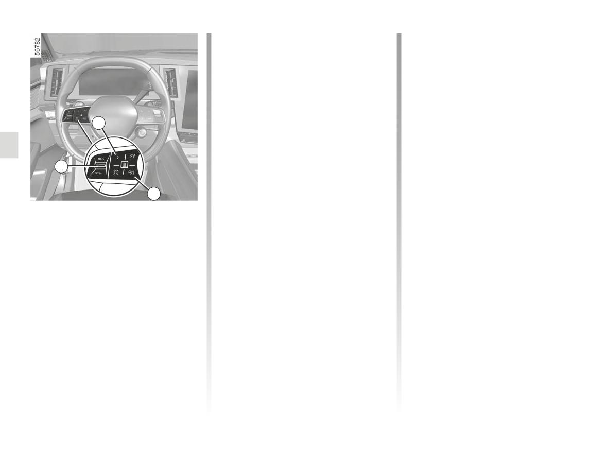
- upwards (RES/+) to return to the
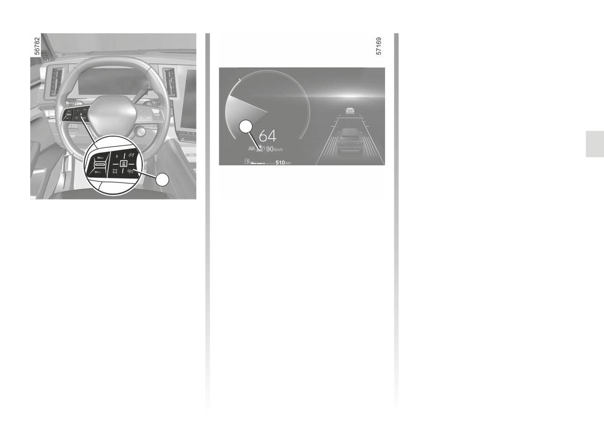
If the system detects a vehicle in your
stored cruising speed;
lane, an outline of a vehicle 10 appears
above the distance gauge 11 on the in-
- downwards (SET/-) to store and
strument panel.
maintain the current speed.
Your vehicle adapts its speed to that
of the vehicle in front and applies the
Safe distance control
brakes if necessary (the brake lights
activation
come on) in order to maintain the dis-
4
As soon as cruise control is activated,
tance displayed on the instrument
the default safe distance 11 is displayed
panel.
in green on the instrument panel. The
Note: the size of the 10 outline varies
default safe distance corresponds to
according to the distance separating
3
approximately two seconds (see follow-
you from the vehicle in front. The larger
ing pages).
the outline, the closer the vehicle in
6
front.
Controlling cruising speed9
You can resume control of the vehicle
Setting the cruising speed
speed at any time by:
You can vary the speed by pressing re-
- putting the function on standby:
peatedly (for low variation) or pressing
and holding (for high variation) the con-
- by pressing the brake pedal;
trol 3:
or
- upwards (RES/+) to increase the
- by pressing the switch 4 (0);
speed;
- by pressing and holding the clutch
- downwards: (SET/-) to decrease the
pedal (vehicles equipped with a
speed.
manual gearbox);
- deactivation of the function by press-
ing the general Start/Stop switch 6.
For vehicles equipped with an auto-
matic gearbox, when automatically
adapting the speed to the signs and/
or road surface, it is possible to ignore
these events. Press the 3 control:
2.118
ADAPTIVE CRUISE CONTROL (10/22)
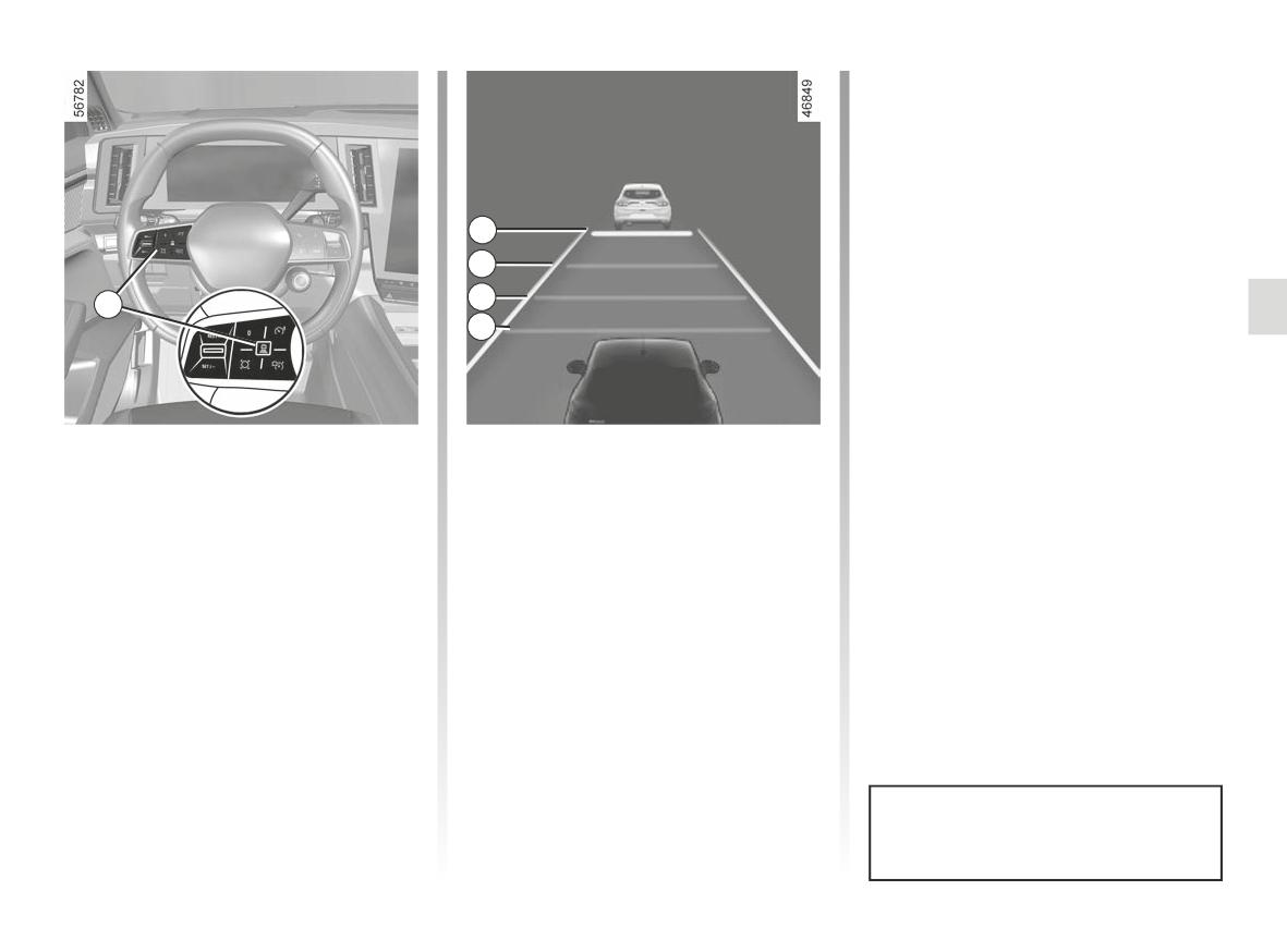
- distance gauge F: intermediate dis-
tance 1 (corresponding to approxi-
mately 1.6 seconds);
- distance gauge G: short distance
(corresponding to approximately
1.2 seconds).
D
The selected distance gauge appears
in green on the instrument panel. The
E
other gauges remain in grey.
F
5
Note: the distance must be set accord-
G
ing to the traffic level, local regulation
and weather conditions.
Adjusting the following
The horizontal distance gauge on the
instrument panel indicates the various
distance
available safe distances:
You can vary the safe distance from the
- distance gauge D: long distance
vehicle in front at any time by pressing
(corresponding to approximately
switch 5 repeatedly.
2.4 seconds);
- distance gauge E: intermediate dis-
tance 2 (corresponding to approxi-
mately 2 seconds);
The safe distance is adjusted by de-
fault on the distance gauge E.
2.119
ADAPTIVE CRUISE CONTROL (11/22)
Then, release the accelerator pedal:
When the vehicle in front sets off again:
the cruise control and safe distance
- if the stop lasts for less than thirty
control will automatically resume the
seconds, the vehicle will start again
speed and distance instructions that
without any action required from the
you had previously selected.
driver.
Note: the driver should always be
Overtaking manoeuvre
ready for sudden incidents while driv-
8
9
If you wish to overtake the vehicle in
ing and remains responsible for con-
front, activating the indicator will tem-
trolling the vehicle: if the system de-
porarily cancel the safe distance con-
tects a pedestrian in the area around
trol and enable an acceleration speed
the vehicle, the automatic restart will
sufficient to complete overtaking.
be inhibited until the next stop.
- if the stop exceeds approximately 30
seconds, you must apply the acceler-
Stopping and starting the
ator pedal or shift control 3 (RES/+)
vehicle on vehicles fitted with
upwards in order for the vehicle to
Exceeding the cruising speed
an automatic gearbox
set off again. The message “Press
The cruising speed may be exceeded
RES/+ or accelerate” will appear on
at any time by applying the accelerator
If the vehicle in front slows down, the
the instrument panel to inform you;
pedal.
system adapts its speed to bring the
vehicle to a complete stop if necessary
If the stop exceeds around three min-
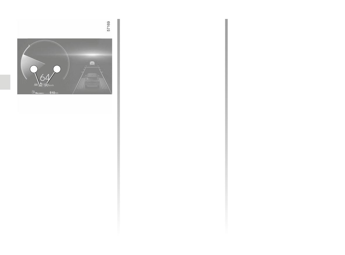
If it is exceeded, the cruising speed 9
utes, the electronic parking brake is
(e.g. in heavy traffic). The vehicle stops
appears in yellow.
automatically applied and the adaptive
a few metres from the vehicle in front.
The distance gauge flashes if the dis-
The Stop and Start function can put the
cruise control is deactivated. The 8 in-
tance between your vehicle and the
engine on standby ➥ 2.7.
dicator light goes out to confirm that the
vehicle in front is less than the safe
function is deactivated.
distance selected: the Safe Distance
Control function is no longer active.
2.120
ADAPTIVE CRUISE CONTROL (12/22)
Putting the function on
- certain driving aids and correction
devices are triggered (active emer-
standby
gency braking, ABS, ESC etc.) ;
You can set the function to standby
- when you press the clutch pedal for a
when:
prolonged period or upon prolonged
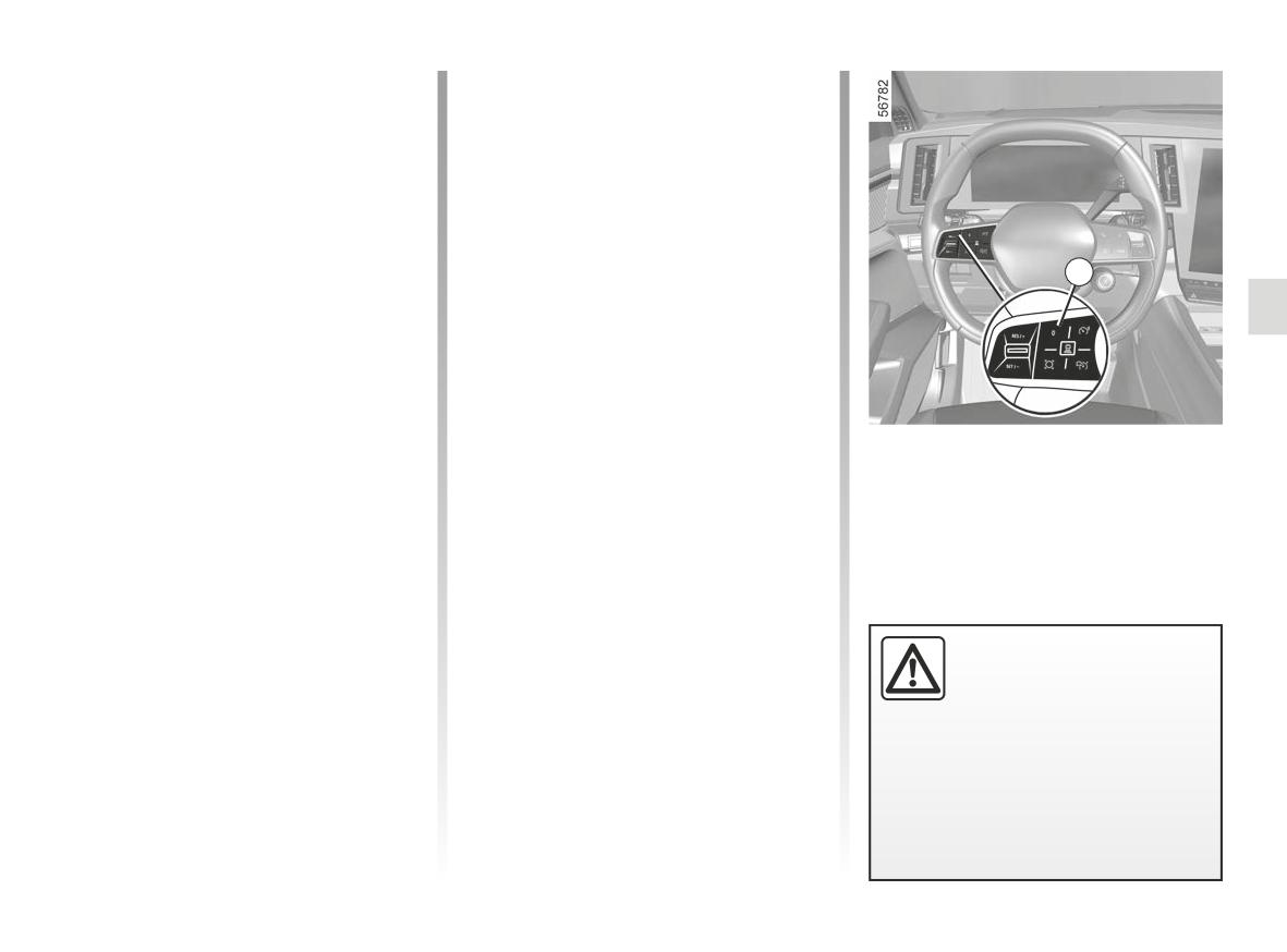
- you press switch 4 (0);
neutral position on vehicles equipped
- you apply the brake pedal while the
with a manual gearbox.
vehicle is moving.
Note: depending on the vehicle, if
the reception of the connected data
4
The function is deactivated by the
system if:
is not optimal, the system automati-
cally switches on standby the advance
- you set the automatic gearbox to P
speed limit sign recognition and/or ad-
or N;
vance recognition of the road layout
- you engage the reverse gear;
functions.
– if the speed is less than 19 mph
The two functions are automatically re-
(30 km/h), for vehicles equipped with
activated as soon as the map data re-
In all circumstances, the standby is con-
a manual gearbox;
ception becomes optimal again.
firmed when the warning lights appear
in grey and the message “Adaptive
- you unbuckle the driver’s seatbelt;
Cruise Ctl Disconnected” appears on
- you open one of the opening ele-
the instrument panel.
ments;
- you press the engine start/stop
button;
- the slope is too steep;
Putting the adaptive cruise
control in standby or switch-
ing it off does not cause a
rapid reduction in speed:
you must brake by applying the
brake pedal if necessary.
2.121
ADAPTIVE CRUISE CONTROL (13/22)
Exit from standby
Depending on the situation, the system
sounds a beep associated with:
Based on the stored cruising speed
- the orange alert H if the situation re-
If a speed is stored, it can be recalled,
quires the driver’s attention;
H
once you are sure that the road condi-
or
tions are suitable (traffic, road surface,
weather conditions, etc.). Shift the con-
- the red alert J accompanied by the
trol 3 (RES/+) upwards within the range
message “Brake” if the situation re-
of valid speeds.
quires the driver’s immediate atten-
When the stored speed is recalled, acti-
tion.
vation of the cruise control is confirmed
In all situations, react accordingly
by the illumination of the cruising speed
J
and perform the appropriate ma-
in green.
noeuvres.
Note: if the stored speed is higher than
the current speed, the vehicle will ac-
celerate to reach that speed.
“Take control of the vehicle”
Based on the current speed
warnings
When the cruise control is set to
In some situations (e.g. coming upon
standby, shifting control 3 (SET/-)
a much slower vehicle, vehicle in
downwards reactivates the cruise con-
front changing lanes quickly etc.), the
trol function without taking into ac-
system may not have time to react.
count the stored speed: it is the speed
at which the vehicle is moving that is
taken into account.
2.122
ADAPTIVE CRUISE CONTROL (14/22)
Ensure that the radar area remains
clean and is not obstructed by snow,
mud, a badly fitted number plate or by
any accessory fitted on the front of the
vehicle (on the grille), or hidden by any
accessory fitted on the front of the vehi-
cle (on the grille or logo, etc.).
Conditions in certain geographical
8
areas may hinder the function, for ex-
ample:
- arid zones, tunnels, long bridges or
lightly used roads without road lines,
without signs or trees nearby;
6
- a military or airport zone.
You must leave such areas in order for
Switching off the function
Temporary unavailability
the function to work.
The adaptive cruise control function is
(radar)
In all cases, if the message is not
deactivated when you press the gen-
The radar is able to detect vehicles
erased after the engine is restarted,
eral Start/Stop 6 switch.
in front of your vehicle. The system
please contact an authorised dealer.
The warning light 8 disappears from
cannot operate correctly if the radar de-
the instrument panel to confirm that the
tection area is obscured or if its signal
function is no longer active.
is disrupted.
If the radar detection area is obstructed
or the radar signal is disrupted, the
message “Front radar no visibility” is
displayed on the instrument panel and
the adaptive cruise control is inter-
rupted. The green warning light 8 dis-
appears to confirm that the function has
been automatically deactivated.
2.123
ADAPTIVE CRUISE CONTROL (15/22)
Temporary unavailability
Operating faults
(camera)
If an adaptive cruise control function
The system cannot operate if the
operating fault is detected, the “Check
camera is obscured (by dirt, mud, snow,
adaptive cruise control” message ap-
condensation, etc.).
pears on the instrument panel and the
adaptive cruise control functions is sus-
In the event of decreased visibility of
pended.
the camera, the performance of the
adaptive cruise control will be reduced.
If an operating fault is detected on one
Remain vigilant.
or more components of the system, the
adaptive cruise control function is inter-
rupted.
The
©
warning light appears on
the instrument panel along with, de-
pending on the malfunction, one of the
following messages:
- “Front camera to check”;
- “Front radar to check”;
- “Camera/Radar to check”;
- “Check vehicle”.
Consult an approved dealer.
2.124
ADAPTIVE CRUISE CONTROL (16/22)
K
L
M
Limitations of system
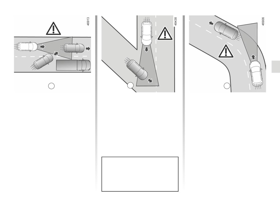
The system cannot detect:
Detection during cornering
operation
- vehicles arriving at intersections: slip
When entering a corner or bend, the
road (e.g. L) etc.;
radar and/or camera may temporarily
Vehicle detection
not be able to detect the vehicle in front
- vehicles driving on the wrong side of
The system detects only vehicles (cars,
(e.g. M).
the road or reversing towards you.
trucks, motorbikes) that are moving in
The system may trigger an accelera-
the same direction as your vehicle.
tion.
A vehicle turning into the same lane
When exiting a bend, the system’s de-
(e.g. K) will be taken into account by the
tection of the vehicle in front may be
system only once it enters the camera
disrupted or delayed.
and radar detection areas.
The system may trigger inappropri-
The system may trigger inappropri-
ate or delayed braking.
ate or delayed braking.
The adaptive cruise control must be
used outside built-up areas, on wide
roads with visible lines.
2.125
ADAPTIVE CRUISE CONTROL (17/22)
N
P
Q
Detection of vehicles in adjacent
Vehicles hidden due to variations in
- vehicles transporting long objects
lanes
ground relief
which exceed the line;
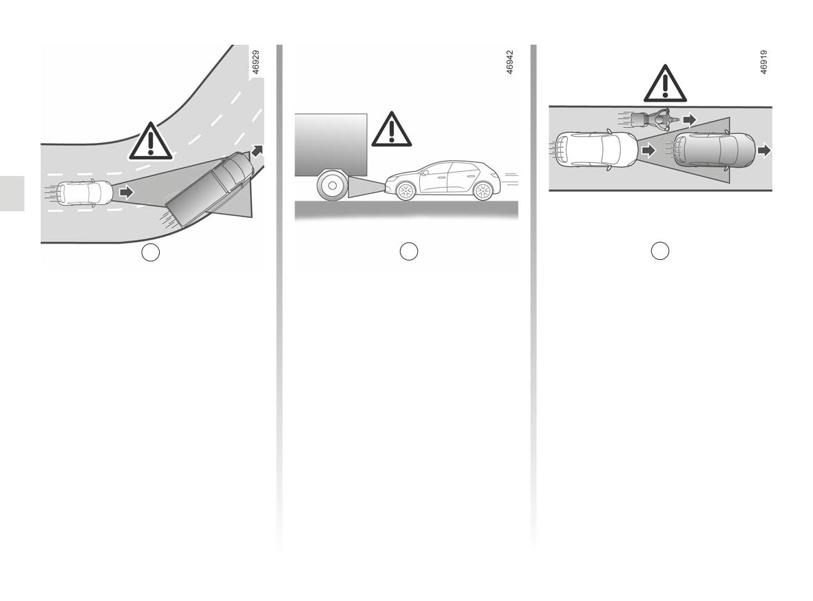
The system may detect vehicles driving
The system will not detect vehicles
- the actual length of tall vehicles
on an adjacent lane when:
hidden due to variations in ground relief
(e.g. P) outside the radar detection
or those located outside of the camera
area (construction machine, agricul-
- you drive into a bend (e.g. N);
and radar detection areas when driving
tural equipment towing vehicle, etc.);
- you are driving on a road with narrow
uphill or downhill.
- vehicles insufficiently centred in the
lanes;
lane;
Vehicles outside the camera and
- the speed of the vehicle on the ad-
radar detection areas.
- narrow vehicles which are very close
jacent lane is slower and if one of
(e.g. Q).
these vehicles is located too close to
The system will react late or not at all
the lane of the other.
if the detected vehicles are outside the
camera and radar detection areas, par-
The system may incorrectly trigger
ticularly in the following cases:
vehicle slowing or braking.
2.126
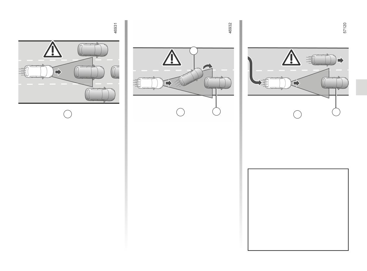
ADAPTIVE CRUISE CONTROL (18/22)
17
S
18
19
R
T
Stationary and slow moving
- vehicles in front 17 that change lane,
vehicles
discovering a stationary vehicle 18
(e.g. S);
When your speed is over approximately
31 mph (50 km/h), the system does
- when vehicles are stationary
19,
not detect:
when you change lane (e.g. T).
- stationary vehicles (e.g R);
- very slow moving vehicles.
When your speed is less than approxi-
mately 31 mph (50 km/h), the system
Always be ready to respond in all
may not react or may react very late
circumstances.
to:
The driver must always be in con-
- stationary vehicles (e.g R);
trol of the vehicle.
– very slow moving vehicles;
The adaptive cruise control does
not trigger an emergency stop and
its braking capability is limited.
2.127
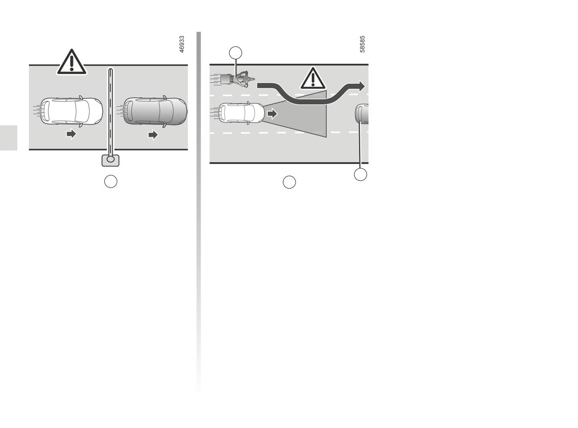
ADAPTIVE CRUISE CONTROL (19/22)
20
21
U
V
Non-detection of fixed obstacles
Detection of vehicles moving into
and objects of a small size
lane at high speed
The system cannot detect:
If your vehicle is overtaken by another
vehicle driving at high speed 20 (motor-
- pedestrians, bikes, scooters, etc. ;
cycle, car, etc.) and the vehicle is tem-
- animals;
porarily between you and the vehicle
- fixed obstacles (toll barriers, walls,
in front 21, the system may trigger
etc.) (e.g. U).
undue acceleration, slowing or brak-
ing.
These are not taken into account by the
system. They do not trigger any alert or
reaction by the system.
2.128
ADAPTIVE CRUISE CONTROL (20/22)
This function is an additional driving aid. It can under no circumstances replace the driver’s responsibility to respect
speed limits and safe distances and to be vigilant.
The driver must always be in control of the vehicle.
Apart from the speed limit signs and road map information from the mapping (vehicles fitted with the “Road sign detection”
function and a subscription), other traffic information (traffic lights, pedestrian crossings, etc.) is not taken into account by the
system. The driver must always adapt their speed to the surroundings and driving conditions, regardless of system indications.
The system should under no circumstances be taken to be an obstacle detector or an anti-collision system.
Use the adaptive cruise control outside built-up areas, on wide roads with visible lines.
System servicing/repairs
- In the event of an impact, the radar and/or camera alignment may be changed and its operation may consequently be af-
fected. Deactivate the system and consult an authorised dealer.
- Any work in the proximity of the radar and/or camera (replacements, repairs, windscreen modifications, paintwork etc.) must
be carried out by a qualified professional.
Only an authorised dealer is qualified to service the system.
2.129
ADAPTIVE CRUISE CONTROL (21/22)
Deactivating the function
You must disable the function if:
- the vehicle is being towed (breakdowns);
- the vehicle is towing a trailer or a caravan;
- the vehicle is being driven in a tunnel or close to a metallic structure;
- the vehicle arrives at a toll point, a roadwork area or on a narrow lane;
- the vehicle is driven on a very winding road (mountain road, etc.) ;
- the vehicle is being driven up or down a very steep slope;
- the visibility is poor (glaring sun, fog, etc.) ;
- the vehicle is being driven on a slippery road surface (rain, snow, gravel, etc.) ;
- the weather conditions are poor (rain, snow, side winds, etc.) ;
- the radar area has been damaged (impacts etc.) ;
- the area of the camera has been damaged (e.g. on the inside or outside of the windscreen);
- the windscreen is cracked or distorted.
In the event of the system behaving abnormally, deactivate it and consult an authorised dealer.
2.130
ADAPTIVE CRUISE CONTROL (22/22)
In the event of system disturbance
Some conditions can disturb or damage the operation of the system, such as:
- the windscreen or bumper is obscured in the area of the radar (dirt, ice, snow, condensation, number plate etc.) ;
- a complex environment (tunnel etc.);
- poor weather conditions (snow, heavy rain, hail, black ice, etc.);
- poor visibility (night, fog etc.);
- being dazzled (glaring sun, lights of vehicles travelling in the opposite direction etc.);
- narrow, winding or undulating road (tight bends etc.) ;
- a vehicle with a significant difference in speed;
- use of mats not adapted to the vehicle. On the driver's side, only use mats suitable for the vehicle, attached with the pre-
fitted components, and check the fitting regularly. Do not lay one mat on top of another. There is a risk of wedging the
pedals.
In this case, the system may brake or accelerate unintentionally.
Many unforeseen situations may affect the system operation. Certain objects or vehicles that can appear in the camera or
radar detection zone may be interpreted by the system incorrectly, possibly leading to inappropriate acceleration or braking.
You should always be attentive to sudden events that might occur while you are driving. Always keep your vehicle
under control by keeping your feet near the pedals, so that you are ready to act in any event.
2.131
ACTIVE DRIVER ASSIST (1/16)
The “Active Driver Assist” is a driv-
The Stop and Go adaptive
The system controls acceleration and
ing aid system for use outside built-up
deceleration of your vehicle using the
cruise control function.
areas, on wide roads and with visible
engine and braking system.
lines.
Depending on the country and sub-
The Stop and Go adaptive cruise con-
scription, based on information from
Depending on the vehicle, this system
trol function can be activated from 0 to
a radar, camera or map data sent via
comprises the “Stop and Go Adaptive
112 mph (180 km/h), depending on the
a GSM connection, the Stop and Go
cruise control function” ➥ 2.110 and
vehicle, according to road conditions
adaptive cruise control gives the option
the “Lane centering assist.” function.
(traffic, weather, etc.).
of maintaining a selected speed, known
It is represented by the following symbol
When these two functions are activated
as the cruising speed, while keeping a
simultaneously, the system allows the
safe distance from the vehicle in front
➥ 2.110.
driver to:
in the same lane. The cruising speed
Note:
can adjust automatically to a speed
- maintain vehicle speed based on a
- the driver must observe the maxi-
limit change (depending on the country
previously saved speed;
mum speed limit and safe distances
and subscription). If the vehicle in front
- adjust the distance between this ve-
in the country where they are driving;
stops, the Stop and Go adaptive cruise
hicle and the vehicle in front;
- the adaptive cruise control can brake
control may brake your vehicle to a
the vehicle up to a third of the brak-
complete stop before setting off again.
- direct the vehicle to the centre of the
ing capacity. Depending on the situ-
lane;
ation, the driver may need to brake
- adapt the vehicle speed to the speed
harder.
shown on the road signs, automat-
ically or after confirmation by the
driver (depending on the vehicle).
Important: you should keep
your feet near the pedals
and your hands on the
The Stop and Go adaptive cruise
steering wheel at all times
control does not trigger an emer-
to prepare for any event.
gency stop and its braking capabil-
ity is limited.
2.132
ACTIVE DRIVER ASSIST (2/16)
The “Lane centering assist.”
Additional information
function
Depending on the vehicle, the “Active
Using information from a camera, the
Driver Assist” function may be used
“Lane centering assist.” function uses
with other driving aid functions.
the steering system to direct the vehi-
Please note that:
cle to the middle of the lane. This func-
- activating the speed limiter causes
tion is only available while the Stop and
deactivation of the system;
Go adaptive cruise control is activated
➥ 2.110.
- the system cannot be activated when
the “Automated park assist” function
If the conditions allow it, the function is
is active;
available between:
- Activating the “Lane centering
- 0 to 112 mph (180 km/h) approxi-
assist.” function suspends the “Lane
mately with a vehicle in front;
departure warning” or “Lane cross-
or
ing prevention” functions if they have
- 37 mph (60 km/h) and 112 mph
been activated. They will be reacti-
(180 km/h) approximately without a
vated when the driver decides to stop
vehicle in front.
the “Lane centering assist.” function.
The “Lane centring” function is a com-
fort feature. It is represented by the
symbol
Note: in the event of a sharp bend,
the function’s lateral retention capaci-
ties are limited and require the driver to
take immediate action on the steering
wheel.
2.133
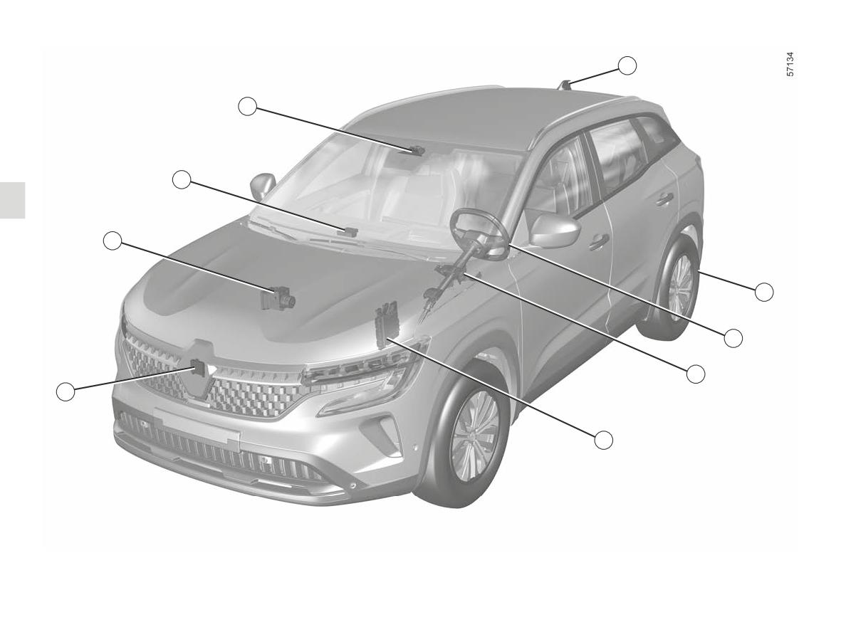
ACTIVE DRIVER ASSIST (3/16)
3
2
1
9
4
5
6
8
7
2.134
ACTIVE DRIVER ASSIST (4/16)
Computer 1
Aerial and maps 3 continued
Radar 8 continued
Receives information from the radar
(depending on the country and sub-
The system’s maximum range is ap-
and camera to determine the vehi-
scription)
proximately 150 metres. This may
cle trajectory and speed (acceleration
vary according to the road conditions
The system can also adjust the vehi-
or braking). Amongst other things, it
(ground relief, weather conditions, etc.).
cle’s speed when approaching a bend
controls activation/deactivation of the
Ensure that the radar area is not ob-
or roundabout.
system (door opening, etc.).
structed (dirt, mud, snow, a badly fitted
Electronic parking brake 4
front number plate), impacted, modified
Camera 2
(including painting) or hidden by any
It the vehicle stationary under certain
Detects markings on the ground, road
accessory fitted on the front of the vehi-
conditions.
signs and the position of vehicles in the
cle (on the grille or logo etc.).
various traffic lanes. It complements the
Capacitive sensor 5
information transmitted by the 8 radar.
Depending on the vehicle, it detects
Active vehicle control 9
Make sure the windscreen is not ob-
hands on the steering wheel
This system provides information on
scured (by dirt, mud, snow, etc.).
vehicle dynamics to the computer 1
Power-assisted steering 6
(speed, lateral acceleration etc.) and
Aerial and maps 3
Operates the front wheels to assist the
acts on the braking system to control
(depending on the country and sub-
trajectory of your vehicle according to
deceleration and to keep the vehicle
scription)
details transmitted by the 1 computer.
stationary.
Road maps and certain driving con-
ditions (roundabouts and cornering)
Engine computer 7
are downloaded according to the jour-
It controls and directs the engine to
ney taken by the vehicle. The system
carry out the required acceleration.
can anticipate deceleration following a
change of the speed limit indicated on
Radar 8
road signs, depending on the parame-
Calculates the distance between your
ters selected by the driver.
vehicle and the vehicle in front.
The radar and camera
zones must be kept clean
and free of any tampering in
order to ensure the proper
operation of the system.
2.135
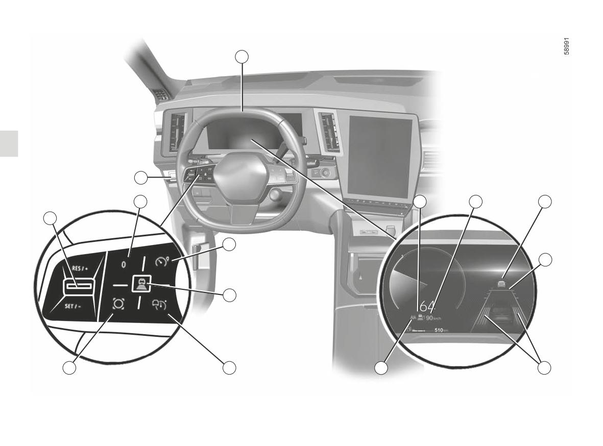
ACTIVE DRIVER ASSIST (5/16)
23
16
11
17
18
19
10
12
20
13
1
5
14
22
21
2.136
ACTIVE DRIVER ASSIST (6/16)
Controls
Displays on the instrument
Steering wheel 23
10
Upwards: activates, increases
panel
The driver must always keep their hands
cruising speed or reminds of
17 Stop and Go adaptive cruise con-
on the steering wheel. If the driver turns
the memorised cruising speed
the steering wheel with enough force,
(RES/+).
trol function warning light
the “Lane centering assist.” function
is suspended to enable the driver to
10
Downwards: activates, decreases
18
Stored cruising speed.
regain control of the vehicle.
cruising speed or stores current
19 Vehicle in front.
speed (SET/-).
Under certain conditions (sharp bends,
20
Stored safe distance
etc.) a vibration may be triggered on the
11
Set active functions to standby
21 Left-hand and right-hand line indi-
steering wheel to warn the driver that
(with cruising speed saved) (0).
cators
they must regain control of the vehicle.
12
Speed limiter activation/deacti-
22 “Lane centering assist.” function
If the driver does not handle the steer-
vation
ing wheel (no hands are detected) the
warning light.
“Lane centering assist.” function is de-
13
Adjusting the following distance.
activated after several warnings.
14
Adaptive cruise control main stop/
start switch.
15
Contextual button.
16
“Lane keeping system” function
activation/deactivation
switch.
2.137
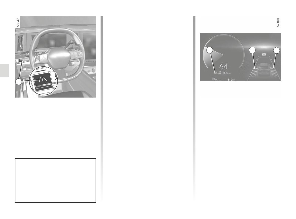
ACTIVE DRIVER ASSIST (7/16)
This selection remains stored when the
vehicle is stopped. The “Lane keeping
system” must be activated. If the warn-
ing light of the 16 button is not lit, press
the button 16
The message “Lane keeping system
22
21
21
activated” appears on the instrument
panel to confirm that the function is ac-
tivated.
This status remains stored when the
vehicle is stopped.
The adaptive cruise control Stop and
16
Go must be switched on. To do this,
press the 14 button to activate it. The
message “Active driver assist ready:
SET to activate” (or, depending on the
Activating the “Lane
vehicle, “Road assist ready: SET to ac-
centering assist.” function
The warning light 22
is displayed
tivate”) will appear on the instrument
The “Lane centering assist.” function
in green and the left-hand and right-
panel.
must be previously selected via the
hand line indicators 21 are displayed on
multimedia screen to be activated.
the instrument panel to confirm that the
The warning light 22
is displayed
From the “Vehicle” World, select to the
function is activated and directing your
in grey on the instrument panel.
“Driving assistance” tab then the “Lane
vehicle to the centre of the lane.
Now push the steering wheel control 10
keeping system” menu.
You can interrupt the “Lane centering
downwards (SET/-).
Select “Lane centering assist.”.
assist.” function at any time by moving
The “Active Driver Assist” consisting of
the steering wheel. As soon as you stop
the adaptive cruise control Stop and Go
turning the steering wheel, the “Lane
and the “Lane centering assist.” func-
centering assist.” function is reacti-
tion is then activated.
vated.
For the MULTI-SENSE “All-Terrain”
Note: you must keep your hands on the
and “Snow” modes ➥ 3.2, it is
steering wheel when using the “Lane
not possible to activate the func-
centering assist.” function.
tion or it automatically deactivates
itself when switching to one of these
modes.
2.138
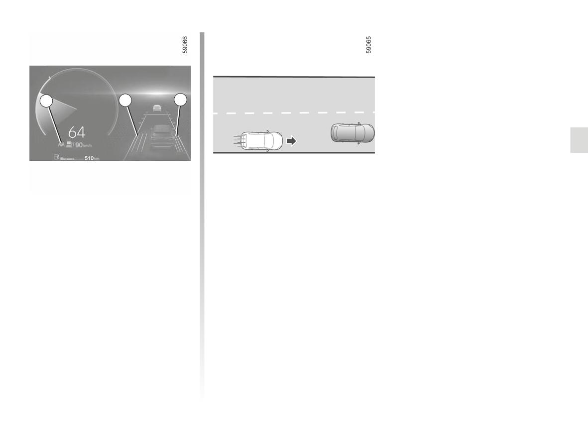
ACTIVE DRIVER ASSIST (8/16)
22
21
21
Adjusting lane position
If certain conditions are met (moder-
(depending on the vehicle)
ate speed, etc.), the vehicle will then
remain in the offset position when you
When the “Lane centering assist.” func-
stop trying to turn the steering wheel.
tion is activated, the 22 warning light is
displayed in green on the instrument
The 21 lines indicate the offset applied.
panel. Turn the steering wheel slightly
To return to the centre of the lane, turn
to the right or left. The vehicle shifts
the steering wheel slightly in the oppo-
to the chosen side without the “Lane
site direction, then stop trying once the
centering assist.“ function being deac-
vehicle has reached the centre.
tivated.
According to certain conditions (e.g.
bend, speed), the vehicle may be
re-centred automatically.
2.139
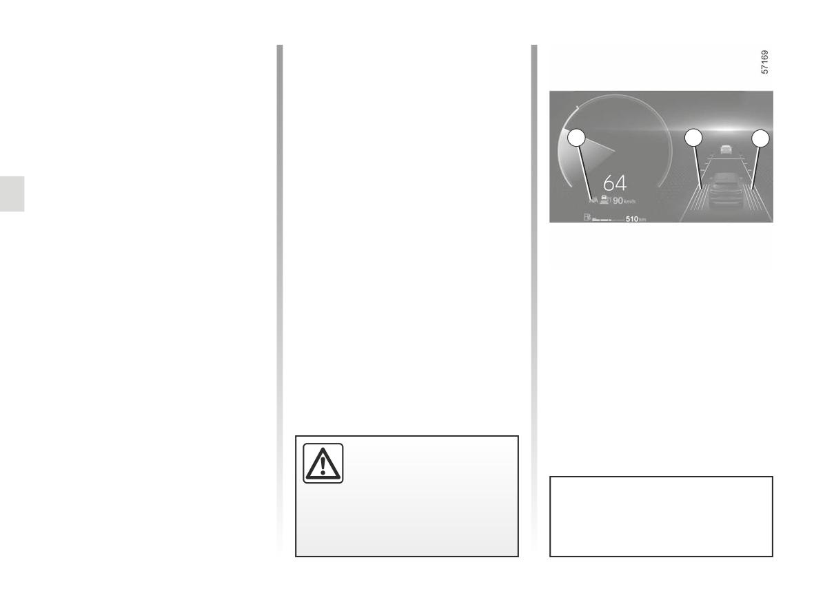
ACTIVE DRIVER ASSIST (9/16)
“Lane centring” function on
- the system is temporarily disrupted
(for example: camera obscured by
standby
dirt, mud, snow,condensation, etc.).
The “Lane centring” function is put on
Certain actions carried out by the driver
standby automatically when:
also suspend the “Lane centring” func-
- the Stop and Go adaptive cruise con-
tion:
trol is put on standby ➥ 2.110 ;
22
21
21
- activating the indicators;
- the system no longer detects the
- turning the steering wheel with
lines or only one line is detected in
enough force.
your lane;
Standby of the function is confirmed by
- the lane is too narrow or too wide;
- the system does not detect any
the 22
warning light and the left-
hands on the steering wheel;
hand and right-hand line indicators 21
appearing in grey on the instrument
- the bend is too sharp;
panel.
- in some driving conditions (rounda-
Once the conditions are met, the func-
bout, intersection, etc.);
tion again directs the vehicle to the
- the vehicle speed is greater than ap-
centre of the lane. The 22
warn-
proximately 112 mph (180 km/h), de-
ing light and left-hand and right-hand
pending on the vehicle;
line indicators 21 are displayed in green
on the instrument panel.
- the vehicle speed is below approx-
imately 37 mph (60 km/h), without
any vehicle in front;
- the vehicle touches or breaches a
line;
Important: you should keep
your feet near the pedals
and your hands on the
steering wheel at all times
You can affect the vehicle trajec-
to prepare for any event.
tory at any point by turning the
steering wheel.
2.140
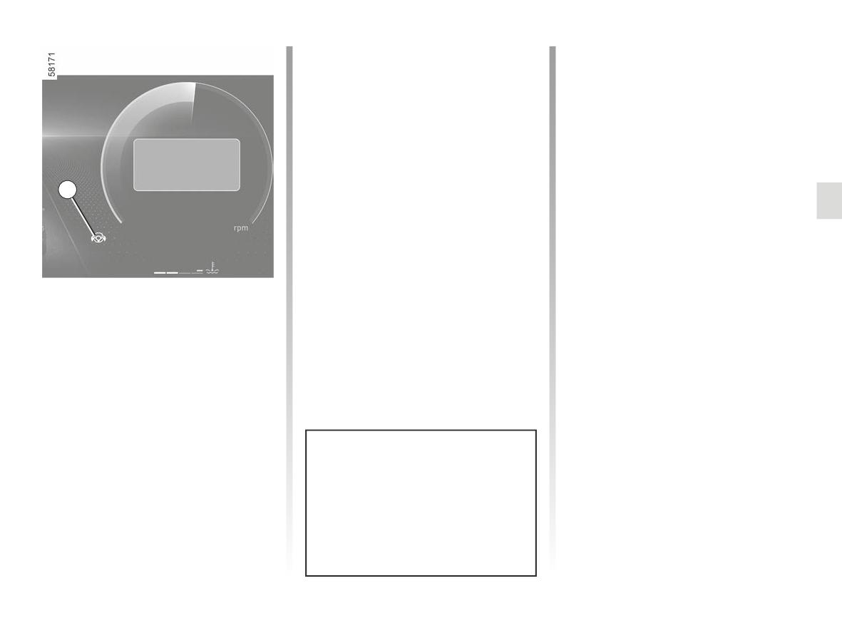
ACTIVE DRIVER ASSIST (10/16)
- after approximately 30 seconds,
If the driver does not put their hands on
the “Keep hands on steering wheel”
the steering wheel after the warning is
displayed, a beep sounds and the 24
message and the 24
warning
light appear in red on the instrument
warning light flashes on the in-
panel, accompanied by a beep that
strument panel.
gets gradually louder;
The brakes are then briefly applied re-
Keep hands on steering
- after approximately 45 seconds,
peatedly to inform the driver that they
wheel
the audio sources go on standby, the
must retake control of the vehicle by
audible signal sounds continually,
putting their hands on the steering
24
wheel.
warning light goes out
the 24
If the driver does not respond, the
and the message “Lane centering
“Active Driver Assist” activates the
deactivated” appears in red on the
hazard warning lights and slows down
instrument panel: the “Lane cen-
the vehicle until it comes to a complete
tring” function is deactivated.
stop.
“Keep hands on steering
The driver can interrupt the manoeuvre,
wheel” warning
as well as “Active Driver Assist”, by put-
When the “Lane centering assist.” func-
ting their hands on the steering wheel,
tion no longer detects your hands on
braking or deactivating the “Lane
the steering wheel, several warning
Centring” function or the Stop and Go
levels will be triggered:
adaptive cruise control function.
- after 15 seconds, the “Keep hands
on steering wheel” message ap-
pears in yellow on the instrument
panel;
In the first two alert levels, when the
system again detects the presence
of the driver’s hands on the steering
wheel, the system stops the alerts.
The function continues to direct the
vehicle to the centre of the lane.
2.141
ACTIVE DRIVER ASSIST (11/16)
“Keep hands on steering
wheel” warning (continued)
In some situations, the “Lane centring”
function may no longer detect your
hands on the steering wheel and may
sound a signal:
- the driver is holding the steering
wheel very lightly;
- the driver is wearing gloves;
- ...
If the “Lane Centring” function is de-
activated due to the driver’s hands
not being detected on the steering
wheel, the Stop and Go adaptive
cruise control function continues to
function.
Warning concerning the
capacitive sensor: the fit-
ting of any accessory on
the steering wheel is pro-
hibited (protective cover, etc.)
2.142
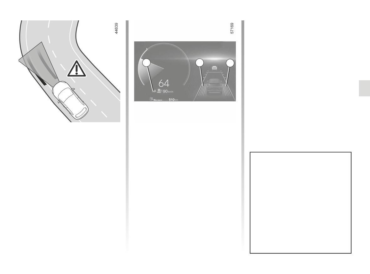
ACTIVE DRIVER ASSIST (12/16)
If the vehicle crosses a line com-
pletely and moves out of its lane or
if the bend is too sharp, the “Lane
centering assist.” function is put
on standby. Standby of the function
is confirmed by the 22
warning
22
21
21
light and the left-hand and right-hand
line indicators 21 appearing in grey on
the instrument panel.
In the case of a sharp bend
If the driver does not intervene, the
function triggers the vibration of the
In the case of a sharp band, and de-
steering wheel to signal that the vehi-
pending on the vehicle speed, the func-
cle is about to breach a line and that
tion’s side retaining capacities will be
the driver needs to carry out immediate
limited and require the driver to carry
action.
out immediate action on the steering
wheel so that the vehicle remains in the
The 22
warning light and the
The “Lane centering assist.” func-
centre of the lane.
left-hand or right-hand line indicator 21
tion cannot assist the driver when
appear in red on the instrument panel.
negotiating a roundabout, intersec-
tion, etc. and may automatically
switch to standby (see previous
pages).
In all cases, the driver must always
turn the steering wheel to manage
the vehicle trajectory under these
driving conditions.
2.143
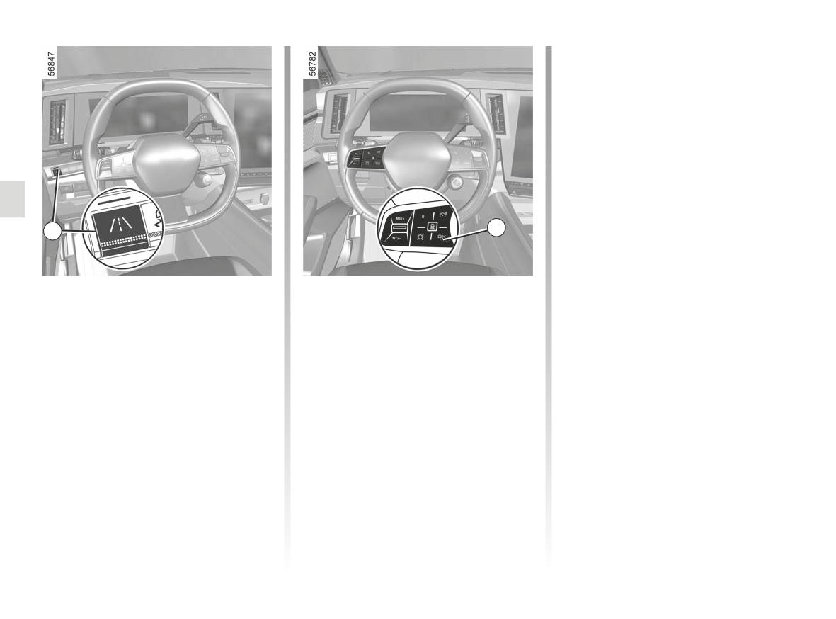
ACTIVE DRIVER ASSIST (13/16)
- the “Lane centering assist.” function
can be deactivated via the multime-
dia screen (from the “Vehicle” World,
select the “Driving assistance” tab,
then the “Lane keeping system”
menu).
warning light and the left-
The 22
hand and right-hand line indicators 21
disappear from the instrument panel.
Operating faults
14
16
If an operating fault is detected on the
“Lane centering assist.” function, the
“Driving assist unavailable” or “Check
Deactivating the “Lane
- the Stop and Go adaptive cruise con-
Driving assist” message is displayed on
trol is deactivated ➥ 2.110.
the instrument panel and the function is
centering assist.” function
deactivated.
The “Lane centering assist.” function is
Note: pressing button 14
si-
The Stop and Go adaptive cruise con-
deactivated if:
multaneously deactivates the adap-
trol function remains in operation.
- you press the 16 switch. The func-
tive cruise control function Stop and
tion’s deactivation is confirmed by
Go and the “Lane centering assist.”
Consult an approved dealer.
the appearance of the “Lane keeping
function;
system deactivated” message on the
- the system will no longer detect the
instrument panel;
driver’s hands on the steering wheel
Note: pressing the 16 switch deac-
for a period over 45 seconds approx-
tivates the “Lane centering assist.”
imately;
function but does not affect operation
of the Stop and Go adaptive cruise
control;
2.144
ACTIVE DRIVER ASSIST (14/16)
The “Active Driver Assist” is an additional driving aid. it can under no circumstances replace the driver's responsibility
to respect speed limits and safe distances and to be vigilant.
The driver must always be in control of the vehicle.
The driver must always adapt their trajectory and speed according to the surroundings and driving conditions, regard-
less of system indications.
Except for lines delimiting lanes and the speed limit signs within the limits of the system’s detection capacity, the road sign in-
formation (other traffic signs, traffic lights, pedestrian crossings, etc.) are not recognised by the system. These do not trigger
any alert or reaction by the system.
“Active Driver Assist” uses the “Stop and Go adaptive cruise control” function and the “Lane centring” function. The system
should under no circumstances be taken to be an obstacle detector or an anti-collision system.
Use the “Active Driver Assist” exclusively outside built-up areas, on wide roads with visible lines.
System servicing/repairs
- In the event of an impact, the radar and/or camera alignment may be changed and its operation may consequently be af-
fected. Deactivate the system and consult an authorised dealer.
- Any work in the proximity of the radar and/or camera (replacements, repairs, windscreen modifications, paintwork etc.) must
be carried out by a qualified professional.
Only an authorised dealer is qualified to service the system.
2.145
ACTIVE DRIVER ASSIST (15/16)
Deactivating the system
You must deactivate the system if:
- the vehicle is travelling on a windy road;
- the vehicle is being towed (breakdowns);
- the vehicle is towing a trailer or a caravan;
- the vehicle is being driven in a tunnel or close to a metallic structure;
- the vehicle arrives at a toll point, a roadwork area or on a narrow lane;
- the vehicle is being driven up or down a very steep slope;
- the visibility is poor (glaring sun, fog etc.);
- the weather conditions are poor (rain, snow, side winds, etc.);
- the vehicle is being driven on a slippery road surface (rain, snow, gravel, etc.);
- the camera area has been damaged (e.g. interior or exterior windscreen area); the windscreen is cracked or distorted;
- the radar area has been damaged (impacts, etc.);
- the surface of the steering wheel is damaged or damp.
In the event of the system behaving abnormally, deactivate it and consult an authorised dealer.
2.146
ACTIVE DRIVER ASSIST (16/16)
Some conditions can disrupt or damage the operation of the system, for example:
- obstruction of the windscreen or the radar area (by dirt, ice, snow, condensation etc.) Frequently check the cleanli-
ness and condition of the windscreen, front wiper blades and front bumper;
- a complex environment (tunnel etc.);
- poor weather conditions (snow, heavy rain, hail, black ice, etc.);
- poor visibility (night, fog etc.);
- poor contrast between the vehicle preceding it and the surrounding area (e.g. white vehicle in a snowy area etc.) ;
- being dazzled (glaring sun, lights of vehicles travelling in the opposite direction etc.);
- narrow, winding or undulating road (tight bends etc.);
- the tar lines detected as a line by the system;
- narrowing/widening lanes;
- road markings which are worn, lacking in contrast or very widely spaced from one another (lines partially erased etc);
- multiple markings on the road (roadworks area, slip roads connecting to adjacent motorways, hard shoulder etc.);
- road signs that do not include an arrow, located in a motorway exit;
- an area with low connectivity that makes it impossible to geolocate the vehicle or maps that are not up-to-date;
- a vehicle with a significant difference in speed;
- use of mats not adapted to the vehicle. On the driver’s side, only use mats suitable for the vehicle, attached with the pre-
fitted components, and check the fitting regularly. Do not lay one mat on top of another. There is a risk of wedging the
pedals.
In these cases:
- Risk of unwarranted braking or acceleration;
- Risk of unwanted, incorrect correction or no correction of trajectory.
Many unforeseen situations may affect the system operation. Certain objects or vehicles that can appear in the camera or
radar detection zone may be interpreted by the system incorrectly, possibly leading to inappropriate acceleration or braking.
You should always be attentive to sudden events that might occur while you are driving. Always maintain your vehi-
cle under control by keeping your feet near the pedals and your hands on the steering wheel, so that you are ready
to act in any event.
2.147
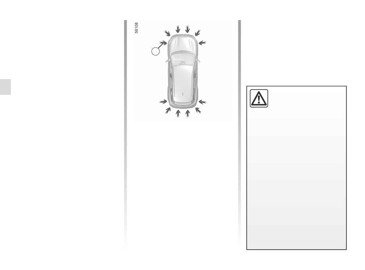
PARKING DISTANCE CONTROL (1/6)
Operating principle
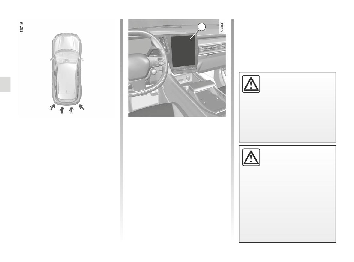
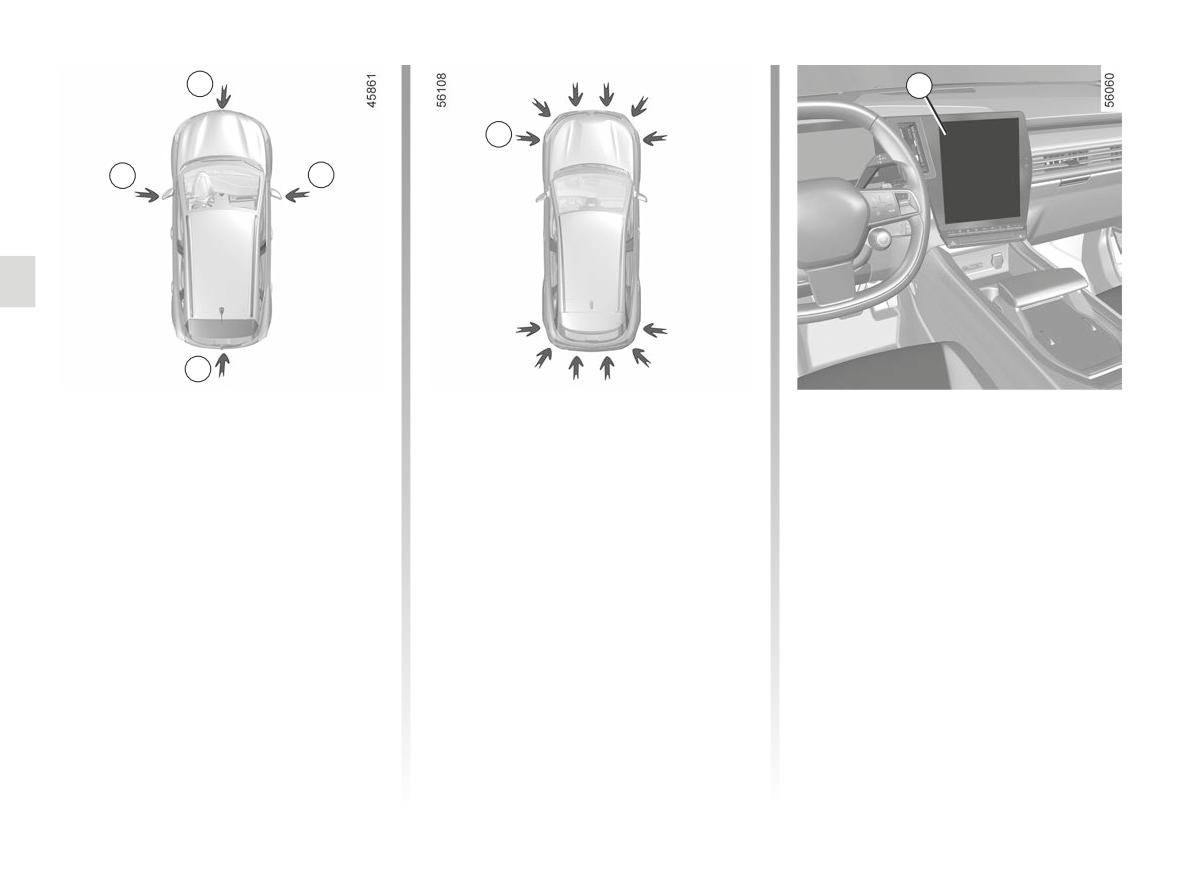
Ultrasonic sensors, indicated by
arrows 1, are fitted in the bumpers to
measure the distance between the ve-
hicle and an obstacle.
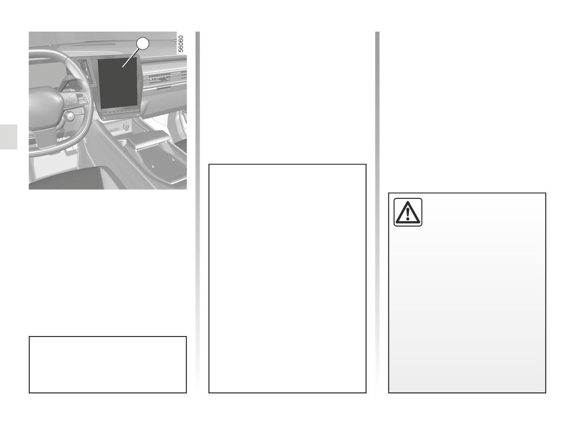
1
This measurement is indicated by
beeps which become more frequent the
closer you come to the obstacle, until
they become a continuous beep when
the vehicle is approximately 20 to
30 centimetres from the obstacle.
This function is an addi-
tional aid that indicates the
Depending on the configuration of the
distance between the vehi-
vehicle, the system detects obstacles
cle and an obstacle whilst
to the front, the rear and the sides of
reversing, using sound signals.
the vehicle.
Location of the ultrasonic
Under no circumstances should it
The parking distance control system
sensors 1
replace the driver’s care or respon-
is only activated when the vehicle is
sibility whilst reversing.
driven at a speed below approximately
Ensure that the ultrasonic sensors indi-
6 mph (10 km/h).
cated by the arrows 1 are not obscured
The driver should always be ready
(by dirt, mud, snow, a badly fitted/at-
for sudden incidents while driv-
The function does not take into account
tached number plate), impacted, mod-
ing: always ensure that there are
towing or carrying systems that are not
ified (including paintwork) or obstructed
no small, narrow moving obstacles
recognised by the system.
by any accessory fitted to the rear and/
(such as a child, animal, pushchair,
or, depending on the vehicle, to the
bicycle, stone, post, etc.) in the blind
front or sides of your vehicle.
spot when manoeuvring.
2.148
PARKING DISTANCE CONTROL (2/6)
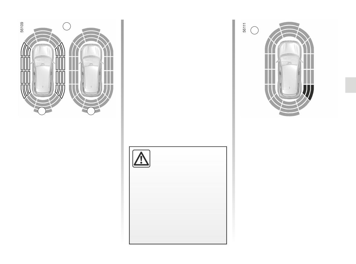
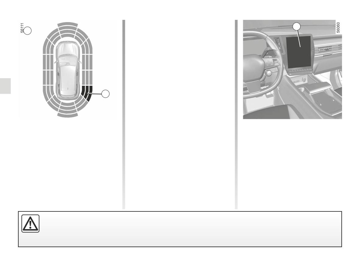
Note: for vehicles fitted with the “360°
2
camera” function ➥ 2.160, analysis of the
C
vehicle surroundings (areas A and B)
is not displayed in “Bird’s eye view” or
“Side view” mode.
Operation
Most objects located less near the
front, rear and sides of the vehicle are
detected.
A
B
Note: the display 2 shows the vehicle
Depending on the distance of the ob-
surroundings and emits beeps.
stacle, the frequency of the beep will
be higher while approaching it, and will
It is necessary to travel a few metres
become a continuous beep around
before the side detection is activated.
20cmawayforobstacles to the sides, and
If all areas have a grey background, the
An impact to the under-
around 30 cm for obstacles to the front
whole area around the vehicle is being
side of the vehicle while
or rear. The green, orange (or yellow
monitored:
manoeuvring (e.g. strik-
depending on the vehicle) and red
ing a post, raised kerb or
zones will be shown on the C display.
- A: analysis of the vehicle surround-
other street furniture) may result in
ings in progress;
Note: in the event of a change in tra-
damage to the vehicle (e.g. defor-
- B: analysis of the vehicle surround-
mation of an axle).
jectory during a manoeuvre, the risk of
ings carried out.
collision with an obstacle may be sig-
To avoid any risk of accident, have
nalled late.
your vehicle checked by an ap-
proved dealer.
2.149
PARKING DISTANCE CONTROL (3/6)
If a side obstacle is detected:
4
D
- the beeps become faster and then
sound continuously as the obstacle
gets nearer. Green, orange and red
zones will be displayed on the dis-
play D;
- if there is no risk of collision, no beep
will sound when approaching the ob-
stacle. Green, orange and red zones
will be displayed interspersed on the
display D.
3
Note: in the event of a change in tra-
jectory during a manoeuvre, the risk of
collision with an obstacle may be sig-
nalled late.
Detection of obstacles to the side
Activation/deactivation
Depending on the direction of the
From the “Vehicle” World of your 4 mul-
wheels, the system determines the tra-
timedia screen, press the “Parking as-
jectory of the vehicle and notifies the
sistance” menu.
driver of any risk or otherwise of a col-
Activate or deactivate areas covered by
lision with an obstacle 3 to the side of
the ultrasonic detectors.
the vehicle.
An impact to the underside of the vehicle while manoeuvring (e.g. striking a post, raised kerb or other street furniture)
may result in damage to the vehicle (e.g. deformation of an axle).
To avoid any risk of accident, have your vehicle checked by an approved Dealer.
2.150
PARKING DISTANCE CONTROL (4/6)
Adjustment
Deactivating the parking
- depending on the model, when the
vehicle is stationary for more than
Depending on the vehicle, with the ve-
distance control manually
approximately 5 seconds and an ob-
hicle stationary, engine running, some
You must disable the function if:
stacle is detected (such as when in a
settings can be adjusted from the multi-
- if towing, carrying or trailer equip-
traffic jam, etc.);
media screen 4.
ment that is unrecognised by the
- when you are in position N;
Please refer to the multimedia instruc-
system is present in front of the ul-
tions for further information.
- when an operating fault is detected.
trasonic detectors;
From the “Vehicle” World, select
Note: if the vehicle is fitted with a
- in the event of damage to the ultra-
the “Parking assistance” menu then
towbar recognised by the system, only
sonic sensors.
“Sound”.
the rear Park Assist function is deacti-
vated.
The following settings can be modified:
Parking distance control
- “Sound type”: select the type of audi-
automatic deactivation
Operating faults
ble warning;
The system deactivates:
When the system detects an operating
- “Volume”: adjust the obstacle detec-
- when the vehicle speed is above ap-
fault, a beep sounds for approximately
tion volume using the volume bar.
proximately 6 mph (10 km/h);
three seconds the first time reverse
gear is selected and is accompanied by
Deactivating the system sound
the message “Check Parking sensors”
Activate or deactivate the parking dis-
shown on the instrument panel. Check
tance control sound.
that your ultrasonic sensors are clean.
Note: if you deactivate the sound, you
If the message remains, contact an ap-
will no longer be notified with beeps
proved dealer.
when approaching an obstacle.
When the vehicle is travelling at a
speed below approximately 6 mph
(10 km/h), some noises (motorcy-
cle, lorry, pneumatic drill etc.) may
trigger the beeping sound of the
parking distance control.
2.151
PARKING DISTANCE CONTROL (5/6)
System servicing/repairs
- In the event of an impact, the alignment of the sensors may be altered and their operation may consequently be affected.
Deactivate the function and consult an authorised dealer.
- Any work in the area where the sensors are located (repairs, replacements, etc.) must be carried out by a qualified profes-
sional.
Only an authorised dealer is qualified to service the system.
System disturbance
Some conditions can disrupt or damage the operation of the system, for example:
- poor weather conditions (rain, snow, hail, black ice, etc.);
- in the event of exposure to strong electromagnetic waves (under high-voltage lines, etc.);
- some types of noise (motorcycle, lorry, pneumatic drill etc.);
- fitting an unsuitable towing ball or hook.
Risk of false alarms or absence of warnings
In the event of the system behaving abnormally, deactivate it and consult an authorised dealer.
2.152
PARKING DISTANCE CONTROL (6/6)
Limitation of the system operation
- The area around the sensors must be kept clean and free of any modifications in order to ensure the proper operation of the
system.
- Small objects moving close to the vehicle (motorcycles, bicycles, pedestrians, etc.) may not be recognised by the system.
- The system may not detect objects that are too close to the vehicle.
- The system may not provide a warning when the other vehicles or objects are travelling at a significantly different speed.
- During a change in trajectory, during a manoeuvre, the system may report obstacles with a delay.
- When the vehicle is towing a trailer, the rear Park Assist system must be deactivated
Deactivating the function
You must disable the function if:
- the area around the sensors has been damaged (rear bumper);
- the vehicle is equipped with a towing device that is not recognised by the system (ball, hook, adapter, etc.).
2.153
ACTIVE EMERGENCY BRAKING IN REVERSE GEAR (1/3)
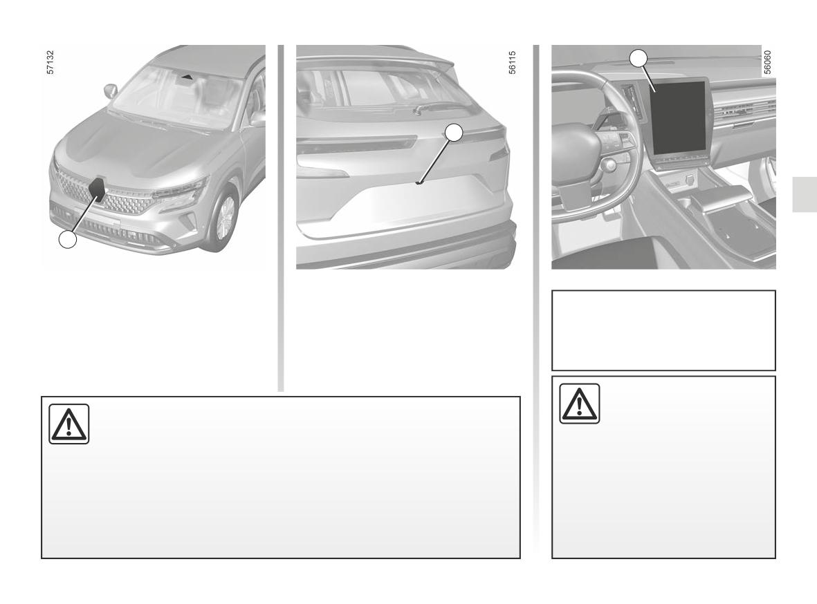
1
This function is an addi-
tional driving aid. This func-
tion is not under any cir-
cumstances intended to
replace the due care and attention
of the driver, who should at all times
be in control of the vehicle.
In addition to the “Parking distance
Operation
control” function ➥ 2.148 and using in-
Fixed rear obstacle detection
formation from the four central sensors
In reverse gear (at speeds of between 2
located at the rear of the vehicle, the
mph and 6 mph (3 km/h and 10 km/h),
system detects fixed obstacles located
if there is a risk of collision with a fixed
An impact to the under-
behind your vehicle. If there is a signif-
obstacle, the system automatically
side of the vehicle while
icant risk of collision, the system auto-
causes the vehicle to brake. Visual
manoeuvring (e.g. strik-
matically causes the vehicle to brake.
ing a post, raised kerb or
Note: make sure that the four central
feedback
2 is displayed on the
other street furniture) may result in
sensors located at the rear of the ve-
multimedia screen 1, accompanied by
damage to the vehicle (e.g. defor-
hicle are not obscured (by dirt, mud,
a beep.
mation of an axle).
snow, etc.).
Once the vehicle has stopped, the vehi-
cle must be held stationary by the driver
To avoid any risk of accident, have
keeping their foot on the brake pedal.
your vehicle checked by an ap-
proved dealer.
2.154
ACTIVE EMERGENCY BRAKING IN REVERSE GEAR (2/3)
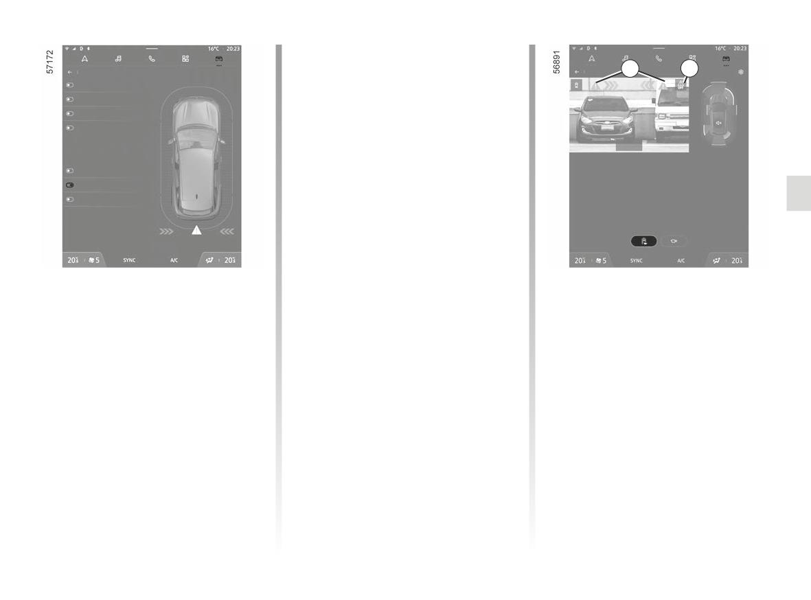
Operating faults
Parking assistance
When the system detects an operating
2
3
Front
fault, active emergency braking in re-
Side
verse gear is automatically deactivated.
Rear
Sound
warning light is displayed
The 3
on the multimedia screen accompanied
by, depending on the type of malfunc-
Rear Cross Parking Alert
tion, the following message on the in-
Rear Active Emergency Braking
strument panel:
Occupant Safe Exit
- “Parking sensors not available”;
or
- “Check Parking sensors”;
or
- “Driving assist unavailable”;
Activating or deactivating the
or
If the vehicle is fitted with a towbar rec-
- “Check Driving assist”.
ognised by the system and a trailer has
system
been connected, active emergency
Depending on the vehicle, the mes-
To activate or deactivate the func-
braking in reverse gear is automatically
sage is accompanied by the display of
tion, select the “Vehicle” mode, then
deactivated and the “Trailer: parking
“Parking assistance”. Select “Rear
the
© warning light on the instru-
sensors off” message is displayed on
Active Emergency Braking”.
ment panel.
the instrument panel while the 3
If the function is deactivated, the
3
Clean the ultrasonic sensors. If there
warning light is displayed on the multi-
is still a problem, contact an approved
warning light is displayed on the
dealer.
media screen.
multimedia screen.
2.155
ACTIVE EMERGENCY BRAKING IN REVERSE GEAR (3/3)
Active emergency braking in reverse gear
This function is an additional driving aid. This function cannot, under any circumstances, replace the vigilance and re-
sponsibility of the driver.
Some climatic and environmental conditions can disrupt or damage the system. As a consequence, the driver should always
be ready for sudden incidents while driving: always ensure that there are no small, narrow moving obstacles (such as a child,
animal, pushchair, bicycle, stone, post, etc.) in the blind spot when manoeuvring.
The triggering of this function may be delayed or prevented when the system detects clear signs of control of the vehicle by the
driver (action on the steering wheel, pedals etc.).
System servicing/repairs
- In the event of an impact, the rear sensors and their performances may be affected. Deactivate the function and consult an
authorised dealer.
- Any work in the area where the sensors are located (repairs, replacements, bumper modifications etc.) must be carried out
by a qualified professional.
Only an authorised dealer is qualified to service the system.
Deactivating the function
You must deactivate the function if the vehicle is being towed (breakdown recovery) or if the vehicle is fitted with a towbar that
is not recognised by the system.
In the event of the system behaving abnormally, deactivate it and consult an authorised dealer.
2.156
REVERSING CAMERA (1/3)
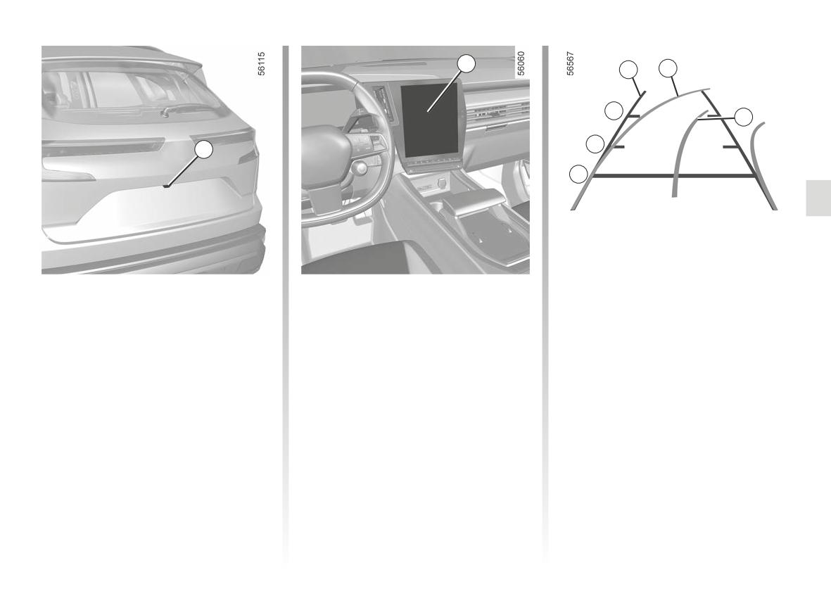
2
3
4
C
5
B
1
A
Operation
Fixed clearance gauge 3
Trailer guide line 5
The fixed clearance gauge comprises
When the vehicle is reversing, the
This is shown in blue on the multimedia
coloured markers A, B and C indicating
camera 1 on the tailgate transmits a
screen 2. This indicates the trajectory
the distance behind the vehicle:
view of the area surrounding the rear of
of the trailer towbar according to the
- A(red) approximately 30 centimetres
the vehicle to the multimedia display 2
steering wheel position. It allows the
from the vehicle;
accompanied by one to three guide
driver to position the towbar as close as
- B(yellow) approximately 70 centime-
lines 3, 4 and 5 (fixed, mobile and trailer
possible to the trailer’s towing head.
tres from the vehicle;
guide lines).
- C(green) approximately 150 centi-
Trailer view
This system uses several guidelines for
metres from the vehicle.
its operation (mobile for trajectory and
In forward gear, if a trailer is attached,
This gauge remains fixed and indicates
fixed for distance). When the red zone
press the “Trailer” button from the
the vehicle trajectory if the wheels are
is reached, use the bumper image to
“Vehicle” mode on your multimedia
in line with the vehicle.
stop accurately.
screen 2 to enable the camera 1 to
Moving guide line 4
transmit a view of the surrounding area
This is shown in blue on the multime-
during approximately 30 seconds.
dia screen 2. It indicates the vehicle tra-
jectory according to the position of the
steering wheel.
2.157
REVERSING CAMERA (2/3)
“Zoom auto” function
2
If an obstacle is detected behind the ve-
hicle, the function “Zoom auto” switches
the current display to a top rear view.
To activate/deactivate the “Zoom auto”
function, refer to the multimedia instruc-
tions.
The screen shows a reverse mirror
Settings
image.
This function is an additional
When the reverse gear is engaged,
aid. It cannot, therefore,
The frames are a representation
from the multimedia screen press the
under any circumstances
projected on a flat surface. This in-
“Settings” button to add or remove
replace the vigilance or the
formation is to not be taken into ac-
the guide lines and adjust the camera
responsibility of the driver.
count when superimposed on a
image settings (brightness, contrast,
vertical object or an object on the
The driver should always be ready
etc.).
ground.
for sudden incidents while driv-
Please refer to the multimedia instruc-
ing: always ensure that there are
Objects which appear on the edge
tions for further information.
no small, narrow moving obstacles
of the screen may be deformed.
(such as a child, animal, pushchair,
In very bright light (snow, vehicle in
bicycle, stone, post, etc.) in the blind
sunshine, etc.), the camera vision
spot when manoeuvring.
may be adversely affected.
If the luggage compartment is open
Make sure that the camera is not
or incorrectly closed, the message
obscured (by dirt, mud, snow, con-
“Tailgate open” appears.
densation etc.).
2.158
REVERSING CAMERA (3/3)
H
F
G
K
J
D E
H J
K
3
D E
3
F G
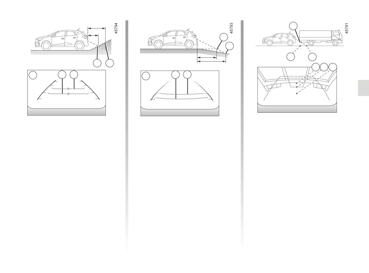
Difference between the
Driving or reversing towards a steep
Driving or reversing towards a
downhill slope
protruding object
estimated distance and
actual distance
The fixed guidelines 3 show the dis-
Position H seems further than posi-
tances as further than they actually are.
tion J on the screen. However, posi-
Driving or reversing towards a steep
tion H is at the same distance as posi-
Therefore, the objects shown on the
uphill slope
tion K.
screen are actually closer on the slope.
The fixed guidelines 3 show the dis-
The trajectory indicated by the fixed
For example, if the screen displays an
tances as closer than they actually are.
and mobile guidelines do not take into
object at G, the actual distance of the
account the height of the object. So
The objects shown on the screen are
object is at F.
there is a risk that the vehicle may col-
actually further away on the slope.
lide with the object when reversing to-
For example, if the screen displays an
wards position K.
object at D, the actual distance of the
object is at E.
2.159
360° CAMERA (1/11)
1
5
4
2
2
3
Using information from cameras 1, 2,
Operation
- bird’s eye view (using the 1, 2, and 3
and 3 located in the front bumper, door
cameras): standard bird’s eye view
The cameras transmit several separate
mirrors and on the tailgate, as well as
and pop-up bird’s eye view (when an
views to the multimedia screen 5.
ultrasonic detectors 4 located in the ve-
obstacle is detected);
They enable you to view the vehicle
hicle bumpers, the feature assists with
surroundings:
- side view (using the camera 2): front
difficult manoeuvres (e.g. parking) by
side view and rear side view;
displaying the vehicle surroundings.
- front view (using the camera 1):
standard front view and panoramic
- 3D view;
Note: make sure that the cameras are
front view;
- trailer view.
not obscured (by dirt, mud, snow etc.).
- rear view (using the camera 3):
The ultrasonic detectors detect obsta-
standard rear view and panoramic
cles at the front, rear and (depending
front view;
on the vehicle) side of the vehicle.
2.160
360° CAMERA (2/11)
5
3
1
Front camera 1
Rear camera 3
The view of the front camera is dis-
The view of the rear camera is dis-
For the rear views, the multimedia
played on the multimedia screen 5.
played on the multimedia screen 5.
screen 5 shows a reverse image
of the rear view as in a rear view
mirror.
In front view or rear view:
when manoeuvring on a
This function is an additional aid. It cannot, therefore, under any circum-
slope, objects shown on
stances replace the vigilance or the responsibility of the driver.
the multimedia screen may
The driver should always be ready for sudden incidents while driving:
be closer or further away than they
always ensure that there are no small, narrow moving obstacles (such
seem.
as a child, animal, pushchair, bicycle, stone, post, etc.) in the blind spot when
manoeuvring.
Take this into account in order
to correctly assess the distance
before any manoeuvre.
2.161
360° CAMERA (3/11)
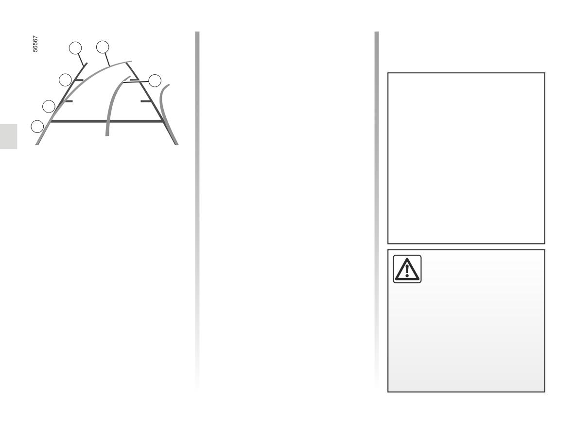
Fixed clearance gauge 6
6
7
The fixed clearance gauge comprises
coloured markers A, B and C indicating
the distance behind the vehicle:
C
8
- A(red) approximately 30 centime-
tres from the vehicle;
The front, rear and side view guide-
- B(yellow) approximately 70 centi-
B
lines are a representation projected
metres from the vehicle;
onto flat ground; this information
- C(green) approximately 150 centi-
A
must not be taken into account
metres from the vehicle.
when superimposed on a vertical
Moving guide line 7
object or an object on the ground.
This is shown in blue on the multime-
Objects displayed on the edge of
dia screen 5. It indicates the vehicle tra-
the multimedia screen may appear
jectory according to the position of the
distorted.
steering wheel in the front and the rear
The “front” or “rear” view transmitted to
In very bright light (snow, vehicle in
view.
the multimedia screen 5 is displayed
sunshine etc.), the camera vision
with one, two or three guide lines 6, 7
Trailer guide line 8
may be adversely affected.
and 8.
This is shown in blue on the multimedia
This system is initially used with the aid
screen 5. This indicates the trajectory
of several gauges (mobile for trajectory
of the trailer towbar in relation to the
and fixed for distance).
steering wheel position.
In the combined represen-
tation from the cameras:
It allows the driver to position the
towbar as close as possible to the trail-
- raised objects (pavement,
er’s towing head.
vehicle, etc.) may appear
distorted in bird’s eye view;
- any objects on top of the vehicle
are not displayed.
2.162
360° CAMERA (4/11)
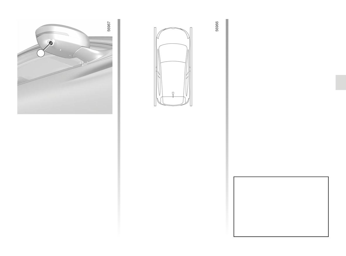
2
Driver’s side front side
Bird’s eye view
camera 2
The bird’s eye view is a combined rep-
The 2camera, fitted in the door mirror,
resentation from cameras 1, 2 and 3.
transmits a side view to the multimedia
It displays a view of the top of the vehi-
screen 5.
cle and its surroundings.
Depending on the vehicle, you can use
This can be used to confirm a view of
the multimedia screen to change the
the vehicle position in relation to its im-
bird’s eye view to the front side view.
mediate surroundings (front, rear and
Please refer to the multimedia instruc-
side).
tions for further information.
In “bird’s eye view” mode, the ob-
jects displayed on the multimedia
screen are actually further away
than they seem. Take this into ac-
count in order to correctly assess
the distance before any manoeu-
vre.
2.163
360° CAMERA (5/11)
360° Camera
360° Camera
360° Camera
Look in all directions
Look in all directions
Look in all directions
9
10
11
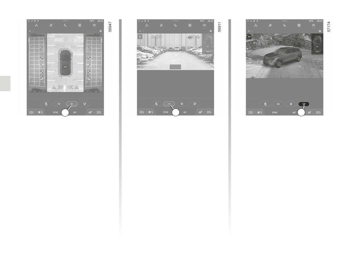
Side views
Front panoramic view or rear
View 3D
On the multimedia screen, by pressing
panoramic view
On the multimedia screen, by press-
the dedicated button 9, you get a view
On the multimedia screen, by pressing
ing the dedicated button 11, you get a
combining a bird’s eye view and two
the dedicated button 10, you get a pan-
3D view allowing you to view the vehi-
side views.
oramic front view.
cle and its surroundings in three dimen-
sions.
When reverse gear is engaged, the
front panoramic view is replaced by a
rear panoramic view.
Note: the front view or the rear view
varies depending on the steering wheel
angle in order to improve the driver’s
view.
2.164
360° CAMERA (6/11)
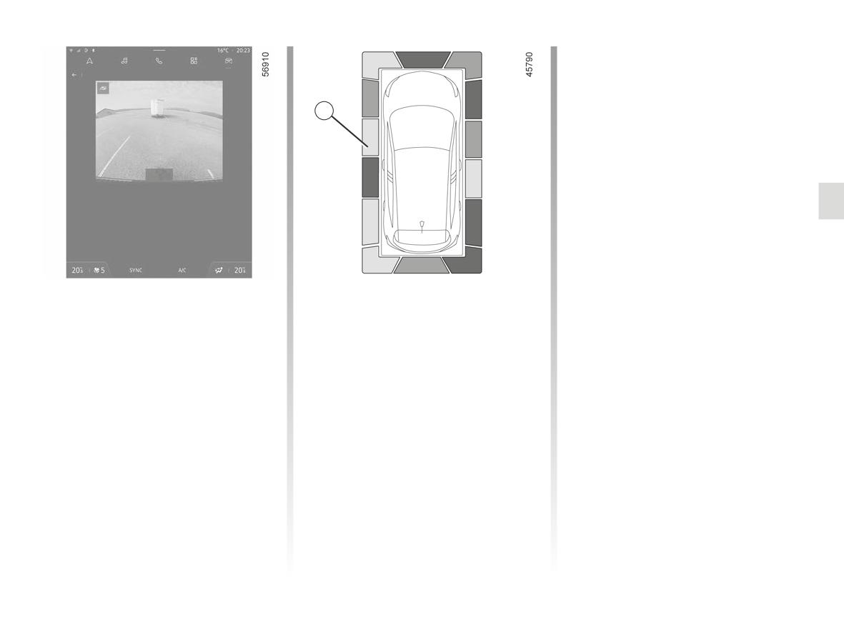
In addition to the sound alert, these in-
dicator lines show the proximity of ob-
Trailer view
stacles via different colours:
- green: obstacle between approxi-
12
mately 50 and 70 centimetres;
- yellow: obstacle between approxi-
mately 30 and 50 centimetres;
Tailgate open
- red: obstacle within approximately
30 centimetres.
These indicator lines also show the lo-
Look in all directions
cation of the obstacles detected relative
to the “Vehicle” symbol.
For more information ➥ 2.148.
Trailer view
From the multimedia screen, when the
“360° Camera” system is displayed, you
In forward gear, if a trailer is attached,
can change the views (e.g. Replace the
press the “Trailer” button from the
rear view with the panoramic rear view).
“Vehicle” mode on your multimedia
screen 5 to enable the camera 3 to
transmit a view of the surrounding area
Obstacle detection
during approximately 30 seconds.
While the system is activated, if the
“Park Assist” function detects one or
more obstacles around the vehicle,
the 12 indicator line is displayed on the
various views.
2.165
360° CAMERA (7/11)
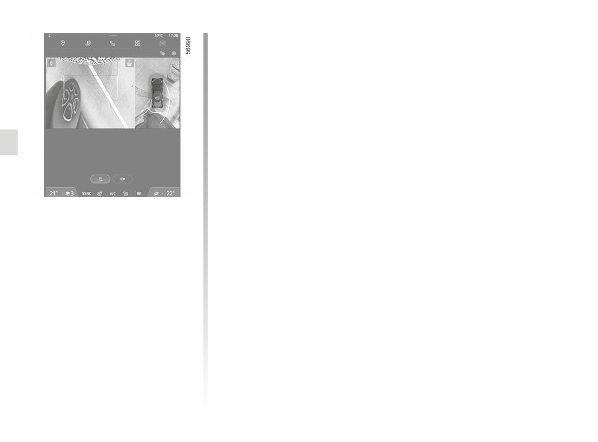
To activate or deactivate the “Zoom
auto" function, please refer to the multi-
360° Camera
media instructions.
Look in all directions
“Zoom auto" function
If an obstacle is detected in the vicinity
of the front or rear of the vehicle, the
“Zoom auto” function switches the cur-
rent display to a specific display (top,
front or rear view).
2.166
360° CAMERA (8/11)
Automatic mode is disabled:
Manual mode
5
- after approximately three sec-
To activate manual mode, with the ve-
onds, when shifting from reverse
hicle stationary and the engine run-
gear to neutral position (on vehicles
ning, from the “Vehicle” mode on your
equipped with a manual gearbox)
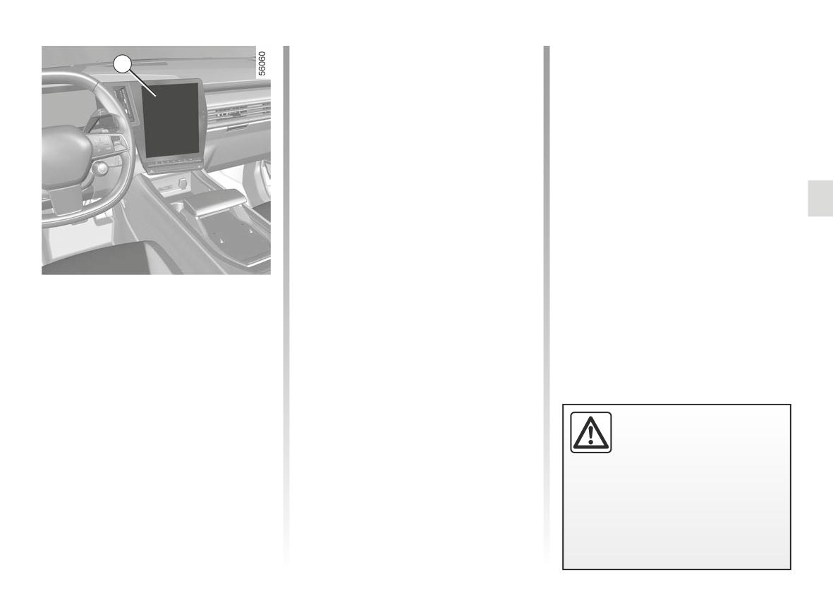
multimedia screen 5, press the “360°
or into N or P position (on vehicles
Camera” menu and the front view and
equipped with an automatic gear-
bird’s eye view will appear on the multi-
box);
media screen.
- after approximately three minutes, if
Manual mode is disabled:
making several movements forwards
- when the vehicle speed moving for-
or backwards (e.g. when manoeu-
ward reaches 6 mph (10 km/h);
vring), before moving the lever into
- when the gear lever has not been
neutral position (on vehicles with a
used for approximately three min-
manual gearbox) or into N or P po-
utes.
sition (on vehicles with an automatic
gearbox);
Activation/deactivation
- when the vehicle speed moving for-
Automatic mode
ward exceeds 6 mph (10 km/h).
With the vehicle stationary and the
engine running, automatic mode is ac-
tivated when the reverse gear is en-
gaged. The rear view and the bird’s
eye view appear on the 5 multimedia
screen.
-Do not use this function
When the reverse gear is quickly shifted
while the door mirrors are in
to forward gear, the rear view and bird’s
folded position.
eye view are replaced by the front view
-Ensure that the luggage
and bird’s eye view on the 5 multimedia
compartment door is properly
screen.
closed before using the function.
- Do not place any objects on or in
front of the cameras.
2.167
360° CAMERA (9/11)
H
F
G
J
K
D E
H J
K
13
D E
13
F G
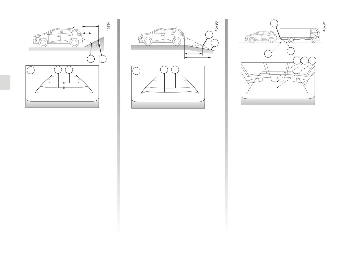
Difference between the
Driving or reversing towards a steep
Driving or reversing towards a
downhill slope
protruding object
estimated distance and
actual distance
The fixed guidelines 13 show the dis-
Position H seems further than posi-
tances as further than they actually are.
tion J on the screen. However, posi-
Driving or reversing towards a steep
tion H is at the same distance as posi-
Therefore, the objects shown on the
uphill slope
tion K.
screen are actually closer on the slope.
The fixed guidelines 13 show the dis-
The trajectory indicated by the fixed
For example, if the screen displays an
tances as closer than they actually are.
and mobile guidelines do not take into
object at G, the actual distance of the
account the height of the object. So
The objects shown on the screen are
object is at F.
there is a risk that the vehicle may col-
actually further away on the slope.
lide with the object when reversing to-
For example, if the screen displays an
wards position K.
object at D, the actual distance of the
object is at E.
2.168
360° CAMERA (10/11)
5
L
L
M
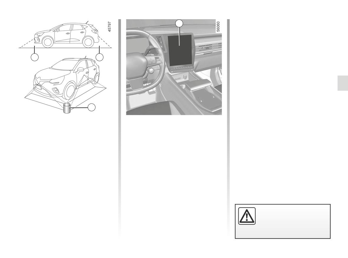
Limitation of the system operation
Adjusting the display
The system is unable to display objects
From the multimedia screen, when the
located in certain areas.
“360° Camera” system is displayed, you
In the front or rear view mode, the
can change the views (e.g. Replace the
system cannot be used to view an
rear view with the panoramic rear view).
object in area L.
In bird’s eye view mode, the system
cannot be used to view a large object in
area M (near the edge of the displayed
area).
For safety reasons, carry
out any adjustments when
the vehicle is not being
driven.
2.169
360° CAMERA (11/11)
If the gear lever is in position R (on an
When shifting from reverse gear to po-
Adjusting the camera
automatic gearbox) or in reverse (on a
sition D (on an automatic gearbox) or
settings
manual gearbox), the following views
into a gear (on a manual gearbox), the
are available:
following views are available:
From the multimedia screen, when the
“360° Camera” system is displayed,
- screen split between the rear view/
- screen split between the front view/
press the “Settings” button to add or
bird’s eye view;
bird’s eye view;
remove the guide lines and adjust the
or
or
camera image settings (brightness,
- panoramic rear view;
- front panoramic view;
contrast, etc.).
or
or
- side views/bird’s eye view (depend-
- side views/bird’s eye view;
Please refer to the multimedia instruc-
ing on the vehicle);
or
tions for further information.
or
– 3D view.
Note: for safety reasons, the views are
- 3D view (depending on the vehicle).
not displayed in the “Settings” menu
When shifting from reverse gear to po-
while the vehicle is moving.
sition P (on an automatic gearbox) or to
neutral position (on a manual gearbox),
the following views are available:
- screen split between the rear view/
bird’s eye view;
or
- panoramic rear view (depending on
the vehicle);
or
- side views/bird’s eye view (depend-
ing on the vehicle);
or
– 3D view (depending on the vehicle).
2.170
PARKING EXIT WARNING (1/4)
A
B
B
B
B
Using information from the radars in-
Special feature
stalled on each side of the rear bumper
Make sure that the radar area A is not
(area A), the system notifies the driver
The system’s detection capability
obscured (by stickers, mud, snow etc.).
when another vehicle appears in the
depends on the vehicle’s surround-
detection zone B.
If a radar is obscured, the message
ings (static objects etc.) and the
“Side radars no visibility” will appear on
The function is activated if:
condition of the bumper etc.
the instrument panel. Clean the area
- reverse gear is engaged;
where the sensors are located.
and
This function is an addi-
- the vehicle is stationary or driving at
tional driving aid. This func-
a low speed.
tion is not under any cir-
cumstances intended to
replace the due care and attention
of the driver, who should at all times
be in control of the vehicle.
2.171
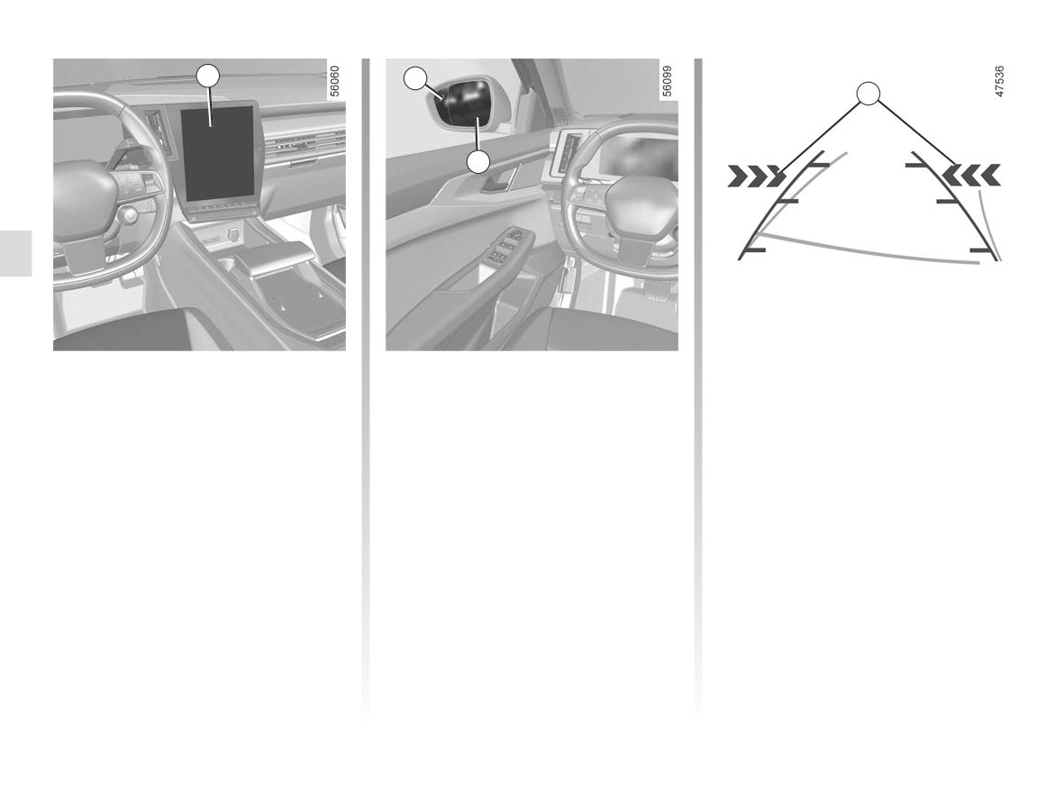
PARKING EXIT WARNING (2/4)
1
2
4
3
Activation/deactivation from
Operation
The indicators 4 on the multimedia
screen show you on which side the ap-
the multimedia screen 1
The function warns you if a vehicle is in
proaching vehicle has been detected.
To activate or deactivate the function,
area B and is approaching your vehicle.
Note: clean the camera regularly so
refer to the multimedia instructions.
When a vehicle is detected, the indica-
that it is not obscured.
Select “ON” or “OFF”.
tors 2 illuminate on both door mirrors 3.
Indicators 2 and 4 are accompanied by
Note: clean the rear view mirrors 3 reg-
an audible signal when your vehicle is
ularly so that the indicators 2 can be
reversing.
seen.
2.172
PARKING EXIT WARNING (3/4)
Operating faults
If the vehicle is fitted with a towbar rec-
ognised by the system and a trailer has
been connected, the parking exit warn-
ing is automatically deactivated and the
following message is displayed on the
instrument panel “Driving assist una-
vailable”.
If the system detects a fault, the mes-
sage “Check Side radars” is displayed
on the instrument panel. Consult an ap-
proved dealer.
Limitation of the system operation
- The radar area should be kept clean and free of any modifications in
order to ensure the proper operation of the system.
- Small objects (motorcycles, bicycles, pedestrians etc.) moving towards to the
vehicle may not be recognised by the system.
Deactivating the function
Due to the presence of sensors
You must disable the function if:
behind the bumper, it is advisable to
- the radar area A has been damaged (rear bumper);
entrust any operation on the bumper
(repair, replacement, paintwork,
- the vehicle is fitted with a towbar that is not recognised by the system.
etc.) to a qualified professional.
2.173
PARKING EXIT WARNING (4/4)
This function is an additional driving aid. This function is not under any circumstances intended to replace the due care
and attention of the driver, who should at all times be in control of the vehicle.
The system should under no circumstances be taken to be an obstacle detector or an anti-collision system.
System servicing/repairs
- In the event of a impact, the position of the radars may be changed, affecting the function. Deactivate the function and con-
sult an authorised dealer.
- Any work in the area where the radars are located (repair, replacement, bodywork etc.) must be carried out by a qualified
professional.
Only an authorised dealer is qualified to service the system.
System disturbance
Some conditions can disrupt or damage the operation of the system, for example:
- a complex environment (underground car park, steel structures etc.) ;
- poor weather conditions (snow, heavy rain, hail, black ice etc.).
Risk of false alarms or absence of warnings
In the event of the system behaving abnormally, deactivate it and consult an authorised dealer.
2.174
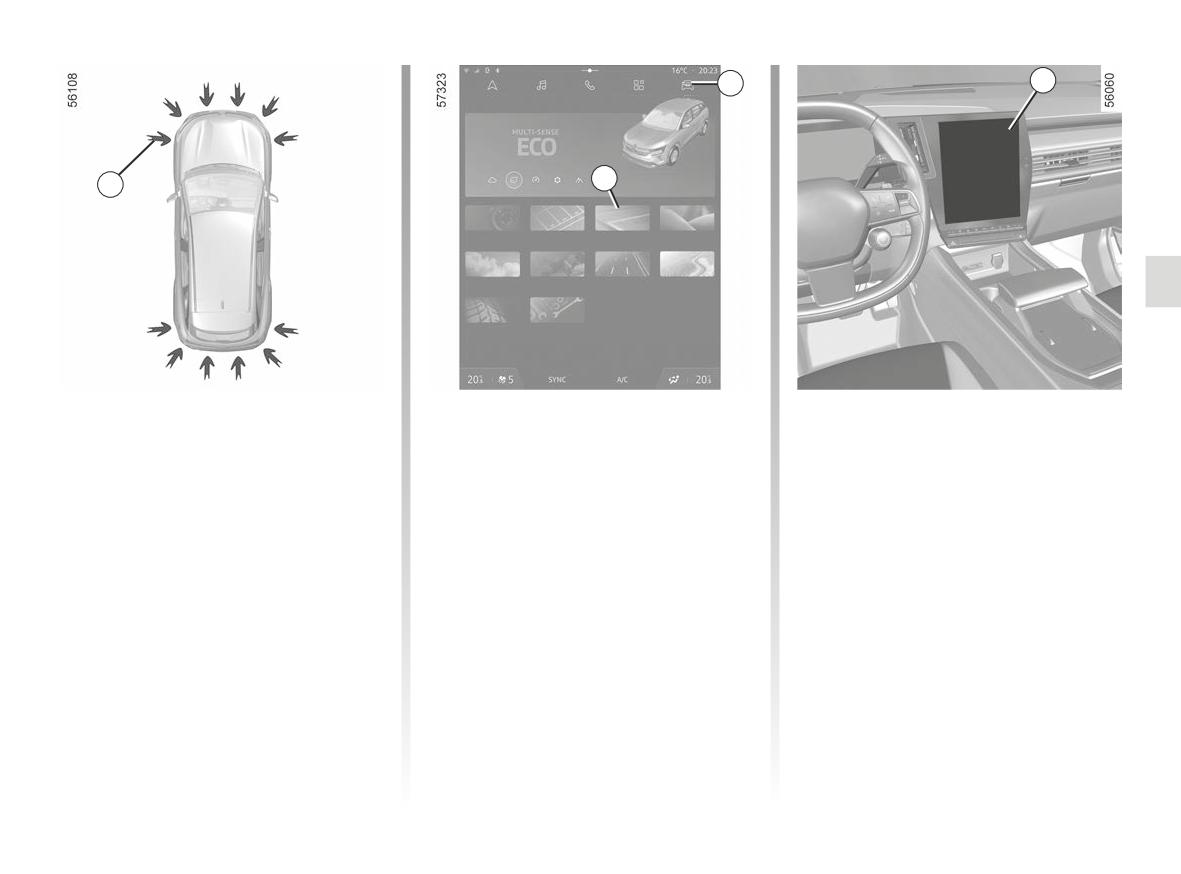
HANDS-FREE PARKING (1/6)
2
4
Configure
3
1
360° Camera
Parking assis-
Hands-free
Seats
tance
park assist
Air quality
Driving Eco
Driving assis-
Dynamic
tance
chassis
Vehicle
Settings
Using ultrasonic detectors as indicated
Switching on
Special features
by the 1 arrows installed in the vehicle
Ensure that the ultrasonic detectors
With the vehicle stationary or driving
bumpers, this function helps to find ac-
indicated by the arrows 1 are not ob-
at less than approximately 19 mph (30
cessible available parking spaces and
km/h), there are several ways to access
scured (by dirt, mud, snow, a badly
assists in the parking manoeuvre.
the function:
fitted number plate, etc.).
Remove your hands from the steering
- from the multimedia screen 4, via the
wheel, you only control:
“Vehicle” mode 2, press the “Hands-
- the accelerator pedal;
free park assist” menu3;
- via the “Hands-free park assist”
- the brake pedal;
widget (if configured by the cus-
- the gear lever.
tomer);
- via the “Favourites” button on the
At any time, you can regain control by
steering wheel (if configured by the
using the steering wheel.
customer);
- depending on the vehicle, via the
“Hands-free park assist” shortcut in
the 360° camera view.
2.175
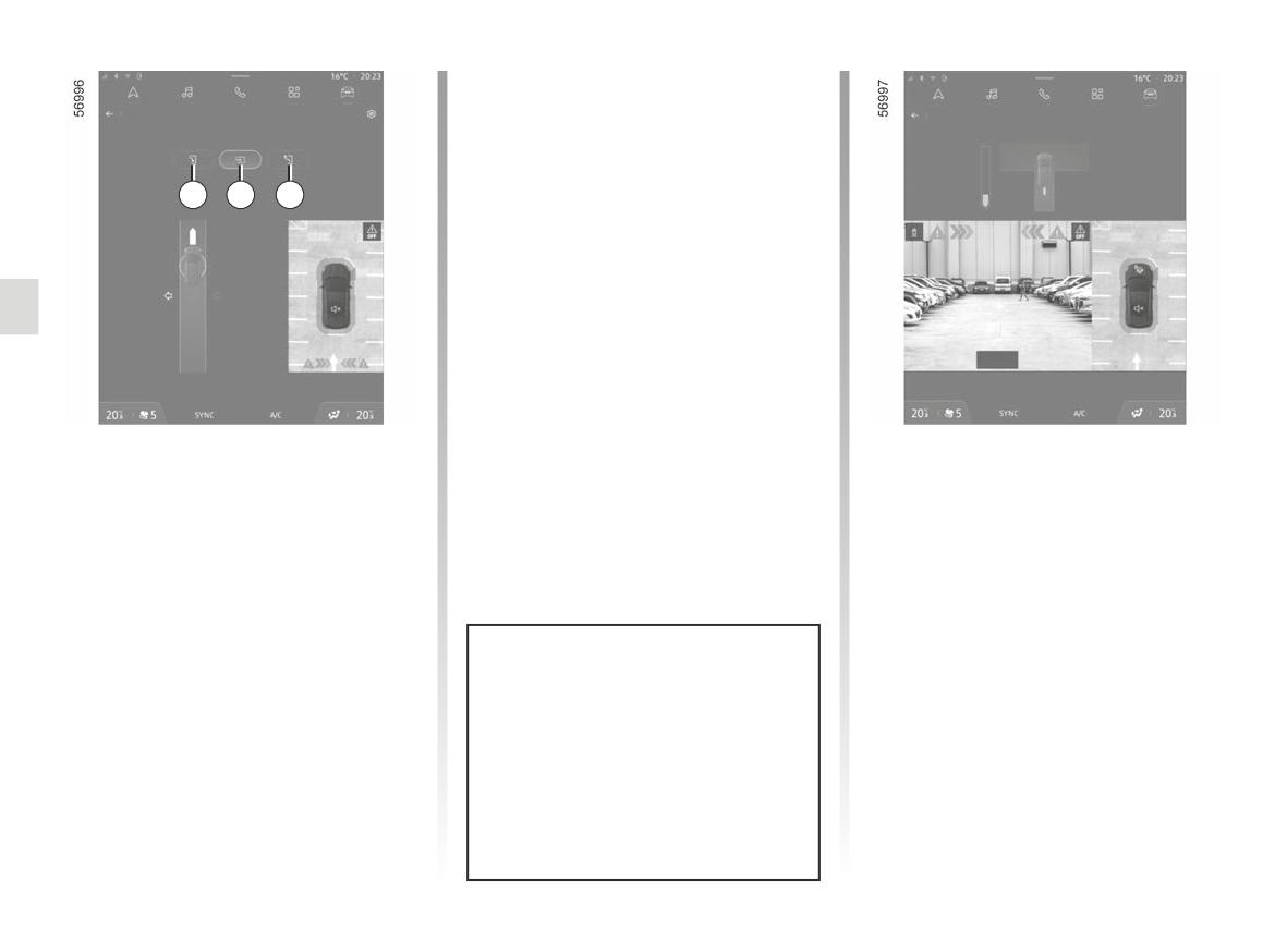
HANDS-FREE PARKING (2/6)
Note: when starting the vehicle, or after
having successfully completed parallel
Hands-free park assist
Hands-free park assist
Select the type of parking and move forward
parking using the system, the default
Select reverse gear
manoeuvre proposed by the system is
assistance in exiting a parallel parking
5
6
7
space.
In other cases, the default manoeu-
vre can be set from the multimedia
screen 4.
Please refer to the multimedia instruc-
tions for further information.
Look in all directions
Look in all directions
Choice of manoeuvre
Operation
The system can perform three types of
Parking
manoeuvre:
As long as the vehicle speed is less
- parallel parking 5;
than 20 mph (30 km/h), the system
- perpendicular parking 6;
looks for available parking spaces on
both sides of the vehicle.
- moving out of a parallel parking
space 7.
Once a space has been found, it is
displayed on the multimedia screen 4,
From the 4 multimedia screen, select
indicated by the letter P. Drive slowly
the manoeuvre to carry out.
The system start up is accompa-
until the “STOP” message appears ac-
nied by activation of the parking dis-
companied by a beep. If more than one
tance control and, on those vehicles
space is detected, you must select the
equipped, the reversing camera
desired space by touching the screen.
or 360° camera to help the driver
visualise the manoeuvre. ➥ 2.148,
➥ 2.157, ➥ 2.160.
2.176
HANDS-FREE PARKING (3/6)
The space turns green on the multime-
Exiting a parallel parking space
- release the steering wheel;
dia screen 4 and is marked by the letter
- Activate the “Hands-free park assist”
- carry out manoeuvres at the front
“P”.
function;
and rear by following the instructions
- Stop the vehicle;
shown on the multimedia screen 4
- Select the “Exit parallel parking
and using the parking distance con-
- select reverse gear.
space” mode;
trol system alerts.
- activate the direction indicators on
Warning light
lights up on the in-
Your speed should not exceed around 4
the side you wish to go out of;
strument panel, along with a beep.
mph (7 km/h).
If all conditions are met, a message will
- Release the steering wheel;
Once the vehicle is in a position to exit
appear on the multimedia screen 4 to
- follow the system instructions on the
start the manoeuvre.
the parking space, the
warning
multimedia screen 4.
- press “OK” to start.
light disappears from the instrument
Your speed should not exceed around 4
panel and a sound signal and message
mph (7 km/h).
Warning light
lights up on the in-
appear on the multimedia screen 4 to
strument panel, along with a beep.
confirm that the manoeuvre is com-
plete.
on the
Once the warning light
instrument panel goes off and a beep
sounds, the manoeuvre has been com-
pleted.
This function is an addi-
tional driving aid.
Therefore, it can under no
When manoeuvring, the
circumstances replace the
steering wheel may turn
driver’s vigilance and responsibility
quickly: do not put your
during manoeuvres (the driver must
hands inside, and make
always be ready to brake).
sure that nothing is caught inside.
2.177
HANDS-FREE PARKING (4/6)
Suspending/resuming the
Cancelling the manoeuvre
The
warning light disappears
manoeuvre
The manoeuvre is cancelled in the fol-
from the instrument panel accompa-
lowing cases:
The manoeuvre is suspended in the fol-
nied by a beep to inform you that the
- the vehicle speed has exceeded
lowing circumstances:
manoeuvre has been suspended. The
4 mph (7 km/h);
reason for suspending the manoeu-
- you take control of the wheel;
- by pressing the “STOP” button;
vre will be displayed on the multimedia
- you have performed more than ten
- the vehicle is stationary for too long;
screen 4.
forwards/backwards movements in
- an obstacle in the direction of move-
Make sure:
one manoeuvre;
ment prevents the manoeuvre from
- the parking distance control sensors
- you have released the steering
being completed;
are dirty or blocked;
wheel;
- the engine stops;
- the vehicle wheels have skidded;
and
- the manoeuvre has been suspended
- a door or the luggage compartment
- that all doors and the boot are closed;
for too long.
is opened.
and
The
warning light disappears
- that no obstacles are in the way of
from the instrument panel accompa-
the direction of movement;
nied by a beep to warn you that the ma-
noeuvre has been aborted. The reason
and
for cancelling the manoeuvre will be
- that the engine is started.
displayed on the multimedia screen 4.
If the
warning light flashes, this
indicates that the system is once again
Function unavailable
available to resume the manoeuvre.
When you select one of the system ac-
tivation methods, if the operating condi-
To resume the manoeuvre, press the
tions are not met, the message “Hands-
“Parking assistance” menu. Warning
free parking unavailable” appears on
the multimedia screen to inform your
light
comes on the instrument
that the function is unavailable.
panel.
Follow the instructions shown on the
multifunction screen 4.
2.178
HANDS-FREE PARKING (5/6)
Operating faults
Note: if there is a fault with the function,
the vehicle is not immobilised.
When the function detects an operating
fault, the following messages are dis-
Take control of the vehicle again imme-
played on the instrument panel:
diately.
- “Check Park Assist” accompanied by
To warn you, the “Take back control”
message appears on the instrument
the
warning light;
panel accompanied by the
warn-
or
ing light and a beep.
- “Check Parking sensors” accompa-
nied, depending on the vehicle, by
the© warning light;
or
- “Check Parking assist” accompa-
nied, depending on the vehicle, by
the© warning light.
Clean the ultrasonic sensors. If there
is still a problem, contact an approved
dealer.
2.179
HANDS-FREE PARKING (6/6)
This function is an additional driving aid. This function is not under any circumstances intended to replace the due care
and attention of the driver, who should at all times be in control of the vehicle. Make sure that the manoeuvre complies
with the applicable traffic regulations in your location.
The driver should always be ready for sudden incidents while driving: always ensure that there are no small, narrow
moving obstacles (such as a child, animal, pushchair, bicycle, stone, post, towing equipment, etc.) in the blind spot when ma-
noeuvring.
System servicing/repairs
- In the event of an impact, the alignment of the sensors may be changed and their operation may consequently be affected.
Deactivate the function and consult an authorised dealer.
- Any work in the area where the sensors are located (repairs, replacements, exterior trim modifications, etc.) must be carried
out by a qualified professional.
Only an authorised dealer is qualified to service the system.
In the event of system disturbance
Certain conditions may disrupt or impair operation of the system, such as poor weather conditions (snow, hail, ice, etc.).
In the event of the system behaving abnormally, deactivate it and consult an authorised dealer.
Risk of erroneous false alarms.
Limitations of the system operation
- The system cannot detect objects located in the sensor blind spots.
- Always visually check that the parking space proposed by the system is still available and contains no obstacles.
- The system should not be used when towing a trailer or when there is a towing or load carrying system on the vehicle or on
surrounding vehicles.
2.180
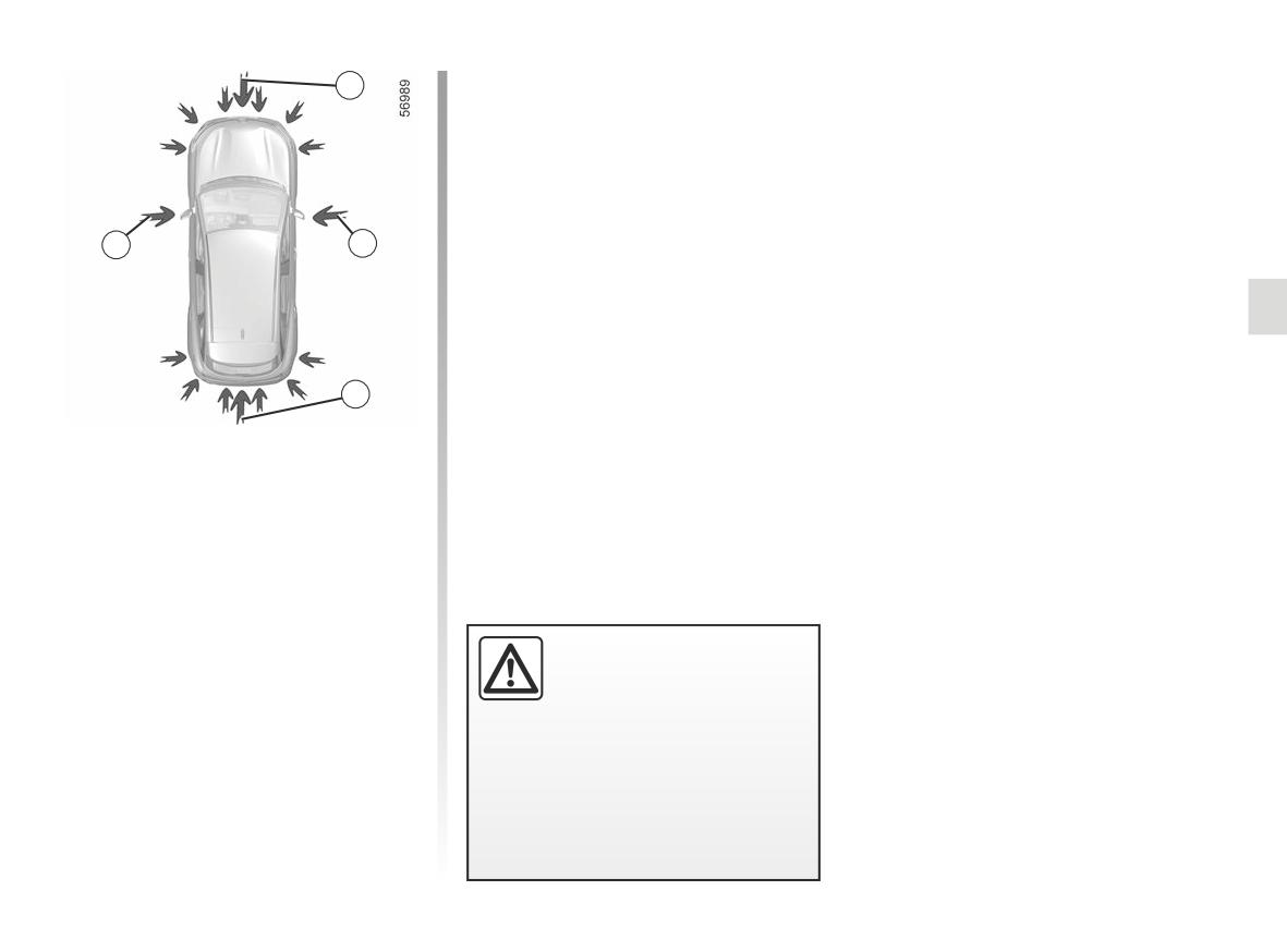
AUTOMATIC PARKING (1/6)
You can take back control of the vehicle
1
at any time by:
- turning the steering wheel;
- releasing the accelerator pedal;
- or by pressing the brake pedal.
1
1
Special features
Ensure that the ultrasonic sensors and
the cameras indicated by the arrows 1
are not obscured (by dirt, mud, snow,
a badly fitted/attached number plate
etc.), impacted, modified (including
1
paintwork etc.) or obstructed by any ac-
cessory fitted to the front or rear of your
This function assists you in parking ma-
vehicle.
noeuvres by taking control of the steer-
ing wheel, brakes, engine and gear
control.
Throughout the manoeuvre, you must
put pressure on the accelerator pedal
(to keep the function working) and take
your hands off the steering wheel.
This function is an addi-
tional driving aid.
Therefore, it can under no
circumstances replace the
driver’s vigilance and responsibility
during manoeuvres (the driver must
always be ready to brake).
2.181
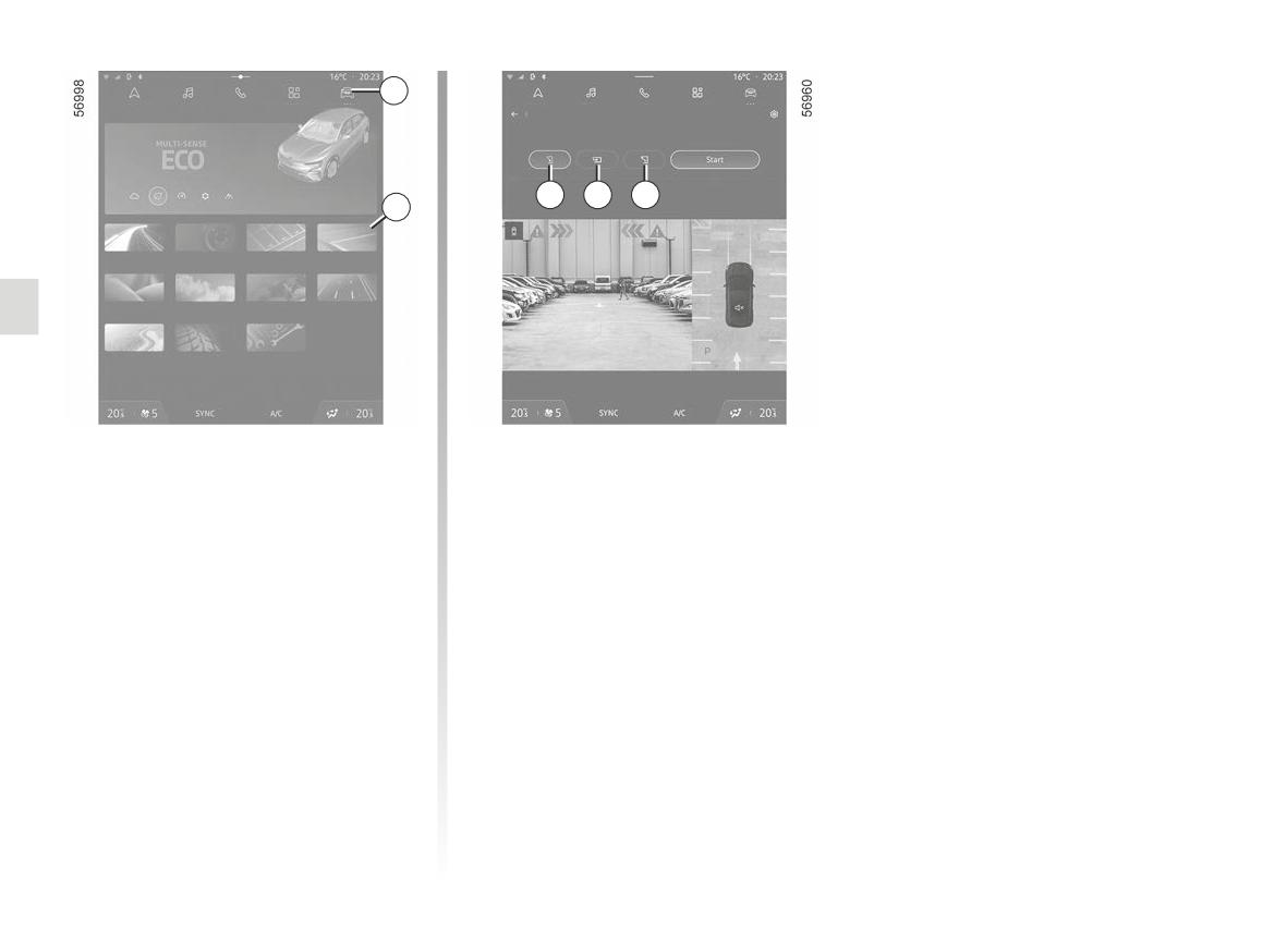
AUTOMATIC PARKING (2/6)
2
Automated park assist
Select the side and then press the start button to initiate the
manoeuvre
Configure
4
5
6
3
Electric
360° Camera
Parking assis-
Automated
tance
park assist
Seats
Air quality
Driving Eco
Driving assis-
tance
Dynamic
Vehicle
Settings
chassis
Look in all directions
Switching on
Choice of manoeuvre
With the vehicle stationary or driving
The system can perform three types of
at less than approximately 19 mph (30
manoeuvre:
km/h), there are several ways to access
- parallel parking 4;
the function:
- perpendicular parking 5;
- Via the “Vehicle” World 2, press the
“Automated park assist” menu 3;
- moving out of a parallel parking
space 6.
- via the “Automated park assist”
widget (if configured by the cus-
From the multimedia screen, select the
tomer);
manoeuvre you wish to perform.
- via the “Favourites” button on the
Note: the other types of parking are not
steering wheel (if configured by the
supported by the system.
customer);
- Via the “Automated park assist”
shortcut in the 360° camera view.
2.182
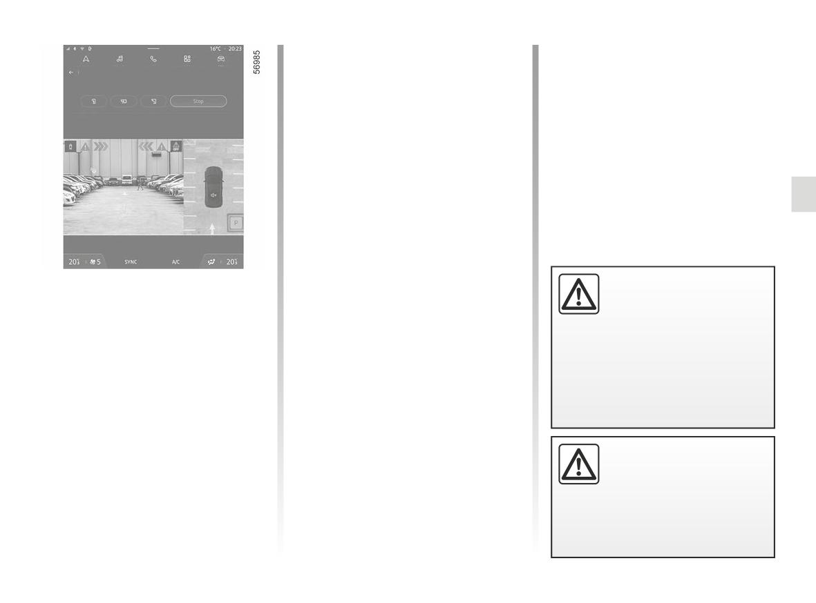
AUTOMATIC PARKING (3/6)
The spaces turns green on the multi-
The “Manoeuvre completed” message
media screen and is marked with the
appears on the multimedia screen to in-
Automated park assist
letter “P".
dicate the end of the manoeuvre. The
Remain vigilant and brake if necessary
assisted parking brake is applied and
- Stop the vehicle;
the P position is engaged.
- press the “START" button.
You can release the accelerator pedal.
lights up on the in-
Warning light
strument panel, along with a beep.
- Release the steering wheel;
- press the accelerator pedal gently;
- follow the system instructions on the
Look in all directions
multimedia screen.
Maintain pressure on the accelerator
pedal throughout the manoeuvre even
Operation
This function is an addi-
when the gears are changing.
tional driving aid.
Parking
The vehicle will start to move. The
Therefore, it can under no
system then controls the steering wheel,
As long as the vehicle speed is less
circumstances replace the
engine, brakes and gear changes.
than 20 mph (30 km/h), the system
driver’s vigilance and responsibility
looks for available parking spaces on
Depending on the pressure on the ac-
during manoeuvres (the driver must
both sides of the vehicle.
celerator pedal, speed varies between
always be ready to brake).
0 and 4 mph (0 and 7 km/h) maxi-
Once a space has been found, it is dis-
mum.
played on the multimedia screen, in-
dicated by the letter “P". Drive slowly
until the "STOP" message appears ac-
companied by a beep. If more than one
When manoeuvring, the
space is detected, you must select the
steering wheel may turn
desired space by touching the screen.
quickly: do not put your
hands inside, and make
sure that nothing is caught inside.
2.183
AUTOMATIC PARKING (4/6)
Parking exit
The “Manoeuvre completed” message
Special features
appears on the multimedia screen to in-
- Activate the “Automated park assist”
- The system does not mount high
dicate the end of the manoeuvre. You
function;
kerbs.
can retake control of the vehicle by re-
- Select the “Exit parallel parking
leasing the accelerator pedal or brak-
- The manoeuvre is impossible if the
space” mode;
ing.
slope is too steep.
- activate the direction indicators on
Note: when the manoeuvre is com-
the side you wish to go out of;
plete, if, after releasing the accelera-
Suspending the manoeuvre
- press the “START" button;
tor, the driver does not act for a certain
The manoeuvre is suspended in the fol-
period of time, the electronic parking
lowing circumstances:
brake is applied and the P position is
Warning light
lights up on the in-
engaged.
- you depress the accelerator pedal
strument panel, along with a beep.
beyond the point of resistance;
- Release the steering wheel;
- a passenger door or the boot is
- press the accelerator pedal gently;
opened;
- follow the system instructions on the
This function is an addi-
- the vehicle has been stationary for
multimedia screen.
tional driving aid.
more than approximately one minute.
Maintain pressure on the accelerator
Therefore, it can under no
pedal throughout the manoeuvre even
The indicator light
goes out on
circumstances replace the
when the gears are changing.
the instrument panel, accompanied by
driver’s vigilance and responsibility
an audible warning. The vehicle is now
The vehicle will start to move. The
during manoeuvres (the driver must
immobilised.
system then controls the steering wheel,
always be ready to brake).
engine, brakes and gear changes.
A message notifies you that the ma-
noeuvre has been suspended and tells
you what you need to do to resume the
manoeuvre.
When manoeuvring, the
Release the accelerator pedal then
steering wheel may turn
press it again to continue the manoeu-
quickly: do not put your
vre.
hands inside, and make
sure that nothing is caught inside.
2.184
AUTOMATIC PARKING (5/6)
Cancelling the manoeuvre
- “Check Park Assist”, accompanied
The indicator light
goes out on
The manoeuvre is cancelled in the fol-
by the symbol
;
lowing cases:
the instrument panel, accompanied by
or
an audible warning.
- you press the “STOP" button;
- “Check Parking sensors”, accompa-
The vehicle stops.
- you open the driver’s door;
nied by the symbol©;
Note: if there is a fault with the func-
- you release the seat belt on the driv-
or
tion, the vehicle is not immobilised.
er’s side;
Take control of the vehicle again. The
- “Check Parking assist”, accompa-
- you apply the electronic parking
“Take back control” message appears
nied by the symbol©.
brake;
on the instrument panel, accompanied
Clean the ultrasonic sensors. If there
by a beep.
- the vehicle has moved too far from
is still a problem, contact an approved
the planned trajectory;
dealer.
- you have performed more than about
Function unavailable
Note: if there is a fault with the function,
ten forwards/backwards movements
the vehicle is not immobilised.
When you press on one of the system
in one manoeuvre;
Take control of the vehicle again imme-
activation methods, if the operating
diately.
- you turn the steering wheel;
conditions are not met, the message
The message “Take back control” ac-
“Automatic Parking unavailable” ap-
- you move the gear lever;
pears on the multimedia screen to
companied by the symbol
ap-
- the vehicle wheels have skidded;
inform your that the feature is unavail-
pears on the instrument panel.
able.
- the engine torque electronic regula-
tor has started
Operating faults
When the function detects an operating
fault, the following messages are dis-
played on the instrument panel:
2.185
AUTOMATIC PARKING (6/6)
This function is an additional driving aid. This function is not under any circumstances intended to replace the due care
and attention of the driver, who should at all times be in control of the vehicle. Make sure that the manoeuvre complies
with the applicable traffic regulations in your location.
The driver should always be ready for sudden incidents while driving: always ensure that there are no small, narrow
moving obstacles (such as a child, animal, pushchair, bicycle, stone, post, towing equipment, etc.) in the blind spot when ma-
noeuvring.
System servicing/repairs
- In the event of an impact, the operation of the sensors may be affected. Deactivate the function and consult an authorised
dealer.
- Any work in the area where the sensors are located (repairs, replacements, exterior trim modifications, etc.) must be carried
out by a qualified professional.
Only an authorised dealer is qualified to service the system.
In the event of system disturbance
Certain conditions may disrupt or impair operation of the system, such as poor weather conditions (snow, hail, ice, etc.).
In the event of the system behaving abnormally, deactivate it and consult an authorised dealer.
Risk of erroneous false alarms.
Limitations of the system operation
- The system cannot detect objects located in the sensor blind spots.
- Always look to check that the parking space suggested by the system is actually still available and free from obstacles before
and during the entire manoeuvre.
- The system should not be used when towing a trailer or when there is a towing or load carrying system on the vehicle or on
surrounding vehicles.
2.186
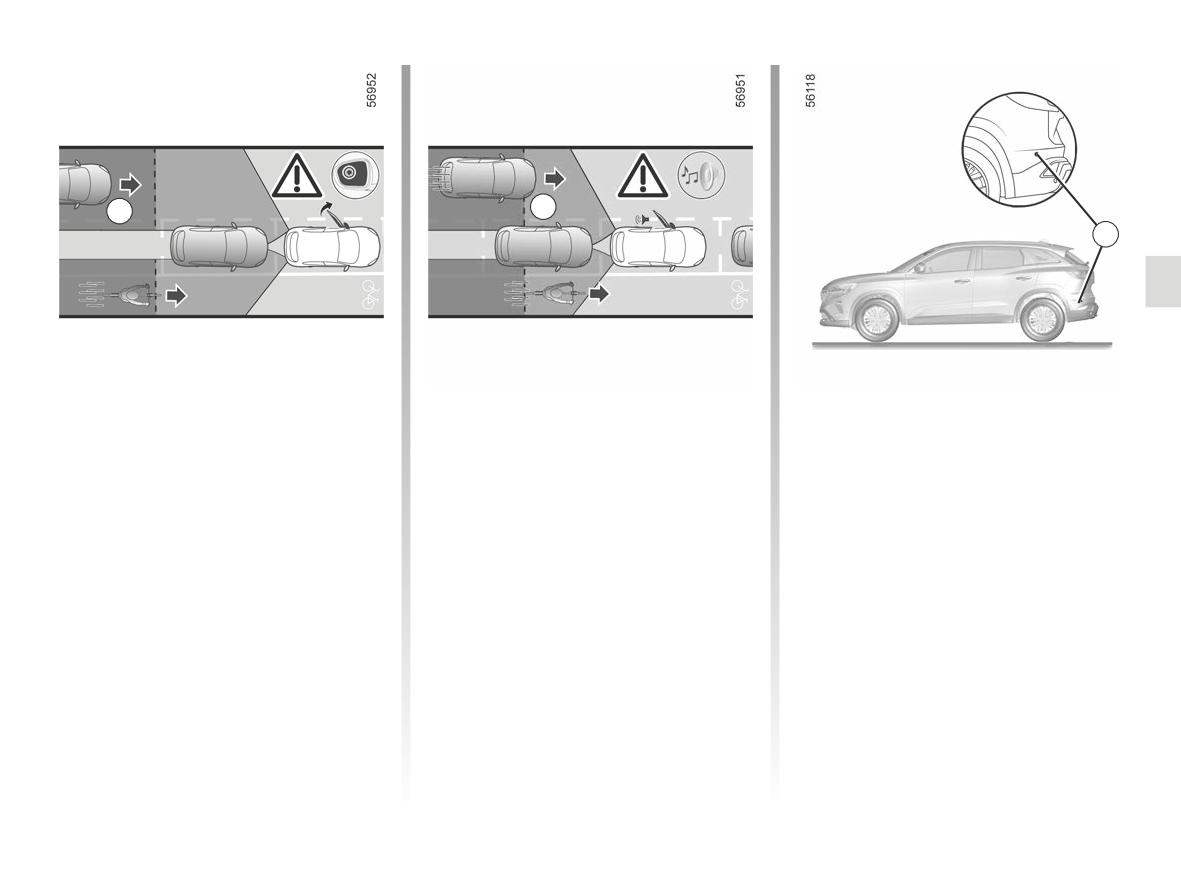
SAFE PASSENGER EXIT (1/3)
B
A
C
Description
Using information from the sensors in-
Special feature
stalled on each side of the rear bumper
This function is an additional driving aid
Ensure that the C area around the
(area C), the function warns the driver:
for the safety of the occupants of the
radars on each side of the rear bumper
vehicle.
- when another vehicle (or motorcycle,
are not obstructed (by dirt, mud, snow
bicycle, pedestrian, etc.) is within the
etc.)
The purpose of the “Safe passenger
detection area A;
If a radar is obscured, the message
exit” function is to warn the driver and/
and
“Side radars no visibility” will appear on
or passengers of the potential danger if
the instrument panel. Clean the area
they open their doors when the vehicle
- when there is a risk of collision with
where the sensors are located.
is stationary.
a vehicle (or motorcycle, bicycle, pe-
destrian, etc.) in the area B.
You must disable the function if:
- the radar area C has been damaged
(rear bumper);
- the vehicle is fitted with a towbar that
is not recognised by the system.
2.187
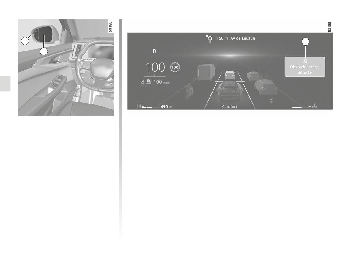
SAFE PASSENGER EXIT (2/3)
1
3
2
Operation
When the detected object is very close,
a beep will sound, along with the warn-
When a door is opened, when a moving
ing message 3 “Lateral obstacle de-
object is detected, the warning light 1
tected” on the instrument panel.
is displayed on the exterior rear view
mirror 2 and, depending on the vehicle,
Note: the system remains active for ap-
the ambient lights on front door come
proximately 45 minutes after the igni-
on.
tion has been switched off.
Note: clean the rear view mirror 2 regu-
larly so that the display of the 1 warning
light is always visible.
2.188
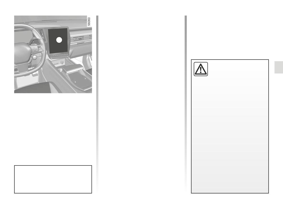
SAFE PASSENGER EXIT (3/3)
Conditions for non-function
Operating faults
– the vehicle is moving and is not com-
If the system detects a fault, the mes-
pletely stationary;
sage “Check Side radars” is displayed
on the instrument panel. Consult an ap-
- the vehicle is locked from the out-
4
proved dealer.
side;
- there are moving objects (motor-
bikes, bicycles, pedestrians, vehi-
cles, etc.) moving towards or near
your vehicle at a low speed that is
This function is an addi-
not considered a risk by the system;
tional driving aid and may
not detect certain vehicles
- the range of the sensors located
or objects in movement
inside the rear bumper is hidden by
in the vicinity of your vehicle. This
objects, such as other particularly
function is not in any way a substi-
wide parked vehicles those parked
tute for the vigilance and responsi-
very close to your vehicle.
Activating/deactivating the
bility of the driver and the occupants
function from the multimedia
If the vehicle is equipped with a towbar
of the vehicle, who are always re-
recognised by the system, the “Driving
screen4
sponsible for paying particular at-
assist unavailable” message displayed
tention to the traffic situation and
To activate or deactivate the function,
on the instrument panel informs you
checking the area before leaving
refer to the multimedia instructions.
that the function is not operational.
the vehicle.
For information on the range of equip-
In the event of system distur-
ment adapted to your vehicle, we advise
bance
you to consult an approved Dealer.
Certain conditions (complex envi-
ronment, poor weather conditions,
etc.) may disrupt or damage the op-
eration of the system, with the risk of
false alarms.
When the vehicle is unlocked, the
function returns to the last saved
status on the multimedia screen.
2.189
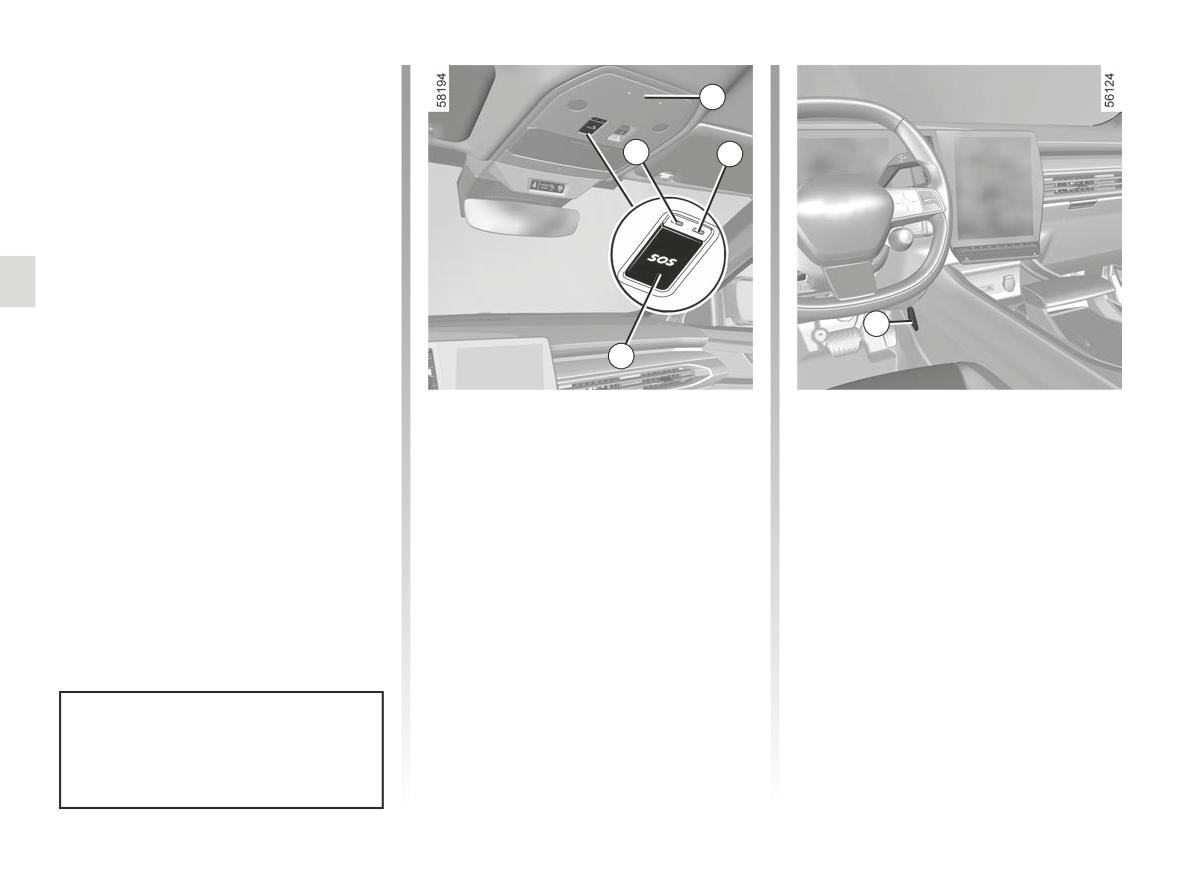
EMERGENCY CALL (1/3)
If the vehicle is equipped, the emer-
gency call function can be used to
1
call the emergency services (without
charge) automatically or manually in
the event of an accident or illness, re-
2
3
ducing the time it takes for the emer-
gency services to arrive.
Note: the emergency call operates:
- in countries covered by the associ-
ated telematics emergency services
and infrastructure compatible with
the system;
5
- depending on the network coverage
4
in the geographical region where the
vehicle is being driven.
1
Microphone.
A call is always made as follows:
If you use the emergency call function
2
System operation/fault warning light:
to report an accident which you have
- the call is set up with the emergency
- red: operating fault.
witnessed, this implies stopping where
services;
3
System operation warning light:
traffic conditions allow in order for the
- send data related to the incident (ve-
- green: operational
emergency services to locate your ve-
hicle identification plate, local time
(network available);
hicle and therefore the location of the
of the call, last positions, direction of
- off: non-operational
reported accident.
the vehicle) ;
(e.g. network unavailable);
In all cases, comply with local legisla-
- green flashing: call in progress.
- voice communication with the emer-
tion.
4
Switch.
gency services;
5
Speaker.
- if necessary, emergency assistance
is called.
Emergency call has two modes:
- automatic mode;
Use the emergency call only in the
- Manual mode.
event of an emergency you are in-
volved in, if you witness an accident
or if you feel ill.
2.190
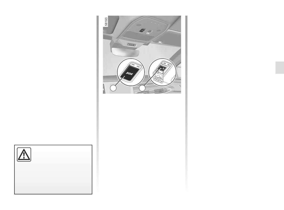
EMERGENCY CALL (2/3)
Automatic mode
In the event of unintended operation, it
is possible to cancel the call by press-
The emergency call starts automati-
ing the 6 button for around two sec-
cally in the event of an accident that
onds, before the call is connected to
has required the activation of the pro-
the call centre.
tective equipment (seat belt pretension-
ers, airbag etc.).
Once a call is established, only the call
centre can end the call.
Test mode
(depending on local laws)
Test mode is reserved exclusively for
Approved Dealers to check that the
emergency call feature is working prop-
erly.
4
6
To activate test mode:
Manual mode
- briefly press the 6 button three times;
To make an emergency call manually:
- wait approximately 15 seconds;
- briefly press the 4 switch;
- briefly press the 6 button three times.
- guide it downwards;
Exit from test mode is automatic.
– press the 6 “SOS” button.
In the event of an acci-
dent, if the location and traf-
fic conditions permit, stay
close to the vehicle in order
to be able answer the call centre
quickly if necessary.
2.191
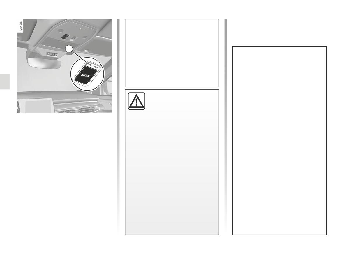
EMERGENCY CALL (3/3)
The system operates with a dedi-
cated battery. The battery service
life is approximately four years
2
(the 2 warning light lights up in
red to warn you when approaching
expiry).
Consult an approved dealer
Without the emergency call feature,
the system is not trackable and will
To guarantee your safety
not be under constant surveillance.
and the proper operation of
Data is automatically and constantly
the system, any operation
erased, and the system stores only
carried out on the battery
the last three positions of the vehi-
Operating faults
(removal, disconnection, etc.) must
cle.
In some cases, the emergency call may
be carried out by a qualified special-
According to local legislation, data
not work (e.g. low battery).
ist.
is only sent in the event of an emer-
When the system detects an operating
Risk of serious burns or electric
gency call. Data sent to the call
fault, the 2 warning light turns red for
shocks.
centre is treated according to the
over 30 minutes; consult an Approved
personal data protection laws appli-
You must respect the replacement
Dealer as soon as possible.
cable in the country where you are
intervals (without exceeding them)
located. The system stores activity
as stated in the maintenance docu-
history data for 13 hours only.
ment.
The vehicle owner has the right of
The battery is a specific type.
access to their data. They can re-
Please ensure it is replaced with the
quest that the data be corrected,
same type.
deleted or locked.
Call an approved Dealer.
2.192
Section 3: Your comfort
Multi-Sense
3.2
Air vents, air outlets
3.4
Automatic climate control
3.7
Air conditioning: information and advice on use
3.13
Multimedia equipment
3.16
Electric windows
3.18
Fixed glass roof
3.20
Sun visor
3.21
Interior lighting
3.22
Passenger compartment storage, fittings
3.24
Accessories socket
3.30
Rear headrests
3.31
Rear bench seat: functions
3.32
Luggage compartment, rear parcel shelf
3.35
Luggage compartment storage
3.43
Transporting objects in the luggage compartment
3.44
Transporting objects: towbar
3.45
Luggage net
3.46
Roof bars, Spoiler
3.48
3.1
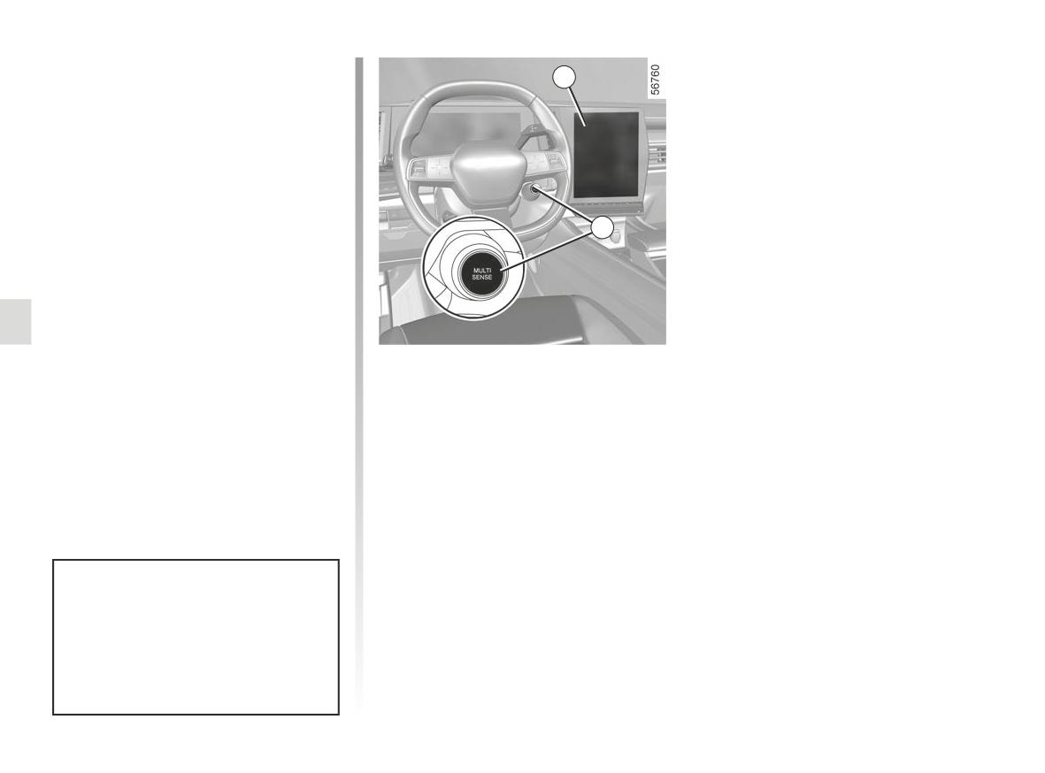
MULTI-SENSE (1/2)
Depending on the vehicle, the Multi-
Sense system enables you to choose
1
from several driving modes that affect
driving, ambient lighting, comfort and
driving position:
- all the modes are preconfigured and
can be customised (ambient lighting,
etc.);
- the Perso mode is customisable.
2
The driving modes influence:
- steering force;
- Electronic Stability Program;
- the response of the engine and gear-
box.
They also affect the:
- the lighting in the passenger com-
Accessing the menu
partment and of the instrument
panel;
You can access Multi-Sense, depend-
- the presentation of the instrument
ing on the vehicle:
panel and the multimedia screen;
- from the multimedia screen 1;
- depending on the vehicle, the driving
- using the steering column control 2.
position.
Please refer to the multimedia instruc-
tions for further information.
Engine settings are specific to each
of the driving modes and cannot be
customised except for the “Perso"
mode.
3.2
MULTI-SENSE (2/2)
Mode Eco
Depending on vehicle, the following
modes are available:
Eco mode focuses on energy saving.
Managing the engine, gearbox and
Perso mode
heating level enables the consumption
to be reduced. ➥ 2.29.
This mode allows the complete configu-
ration of the driving elements, including
Sport mode
engine responsiveness.
This mode enables an increased re-
Snow mode
sponsiveness from the engine and the
gearbox. The steering is firmer.
This mode offers optimal performance
for controlling the vehicle on snowy
Comfort mode
ground.
Using standard vehicle settings, this
All-Terrain mode
mode gives you the best compromise
between comfort and dynamism.
This mode offers optimal performance
for controlling the vehicle on tracks.
In “All-Terrain” and “Snow” mode,
certain driving assistance functions
(Stop and Go adaptive cruise con-
trol, Active Driver Assist, etc.) are
not available or are automatically
After the engine is switched off, the
deactivated when switching to one
You can reset the mode by mode
vehicle will always restart in Comfort
of these two modes.
settings.
mode.
3.3
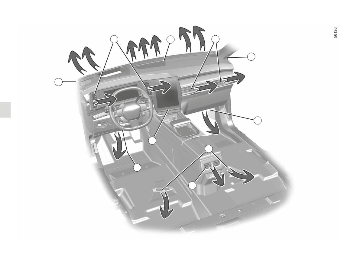
AIR VENTS, air outlets (1/3)
1
2
3
4
4
5
8
6
5
7
1 Driver’s position air vents.
5 Footwell heater outlets for front passengers.
2 Windscreen demisting vents.
6 Footwell heater outlets for rear passengers
3
Passenger air vents.
(depending on the vehicle).
4
Side window demisting vents.
7
Rear passenger central air vents.
8
Control panel.
3.4
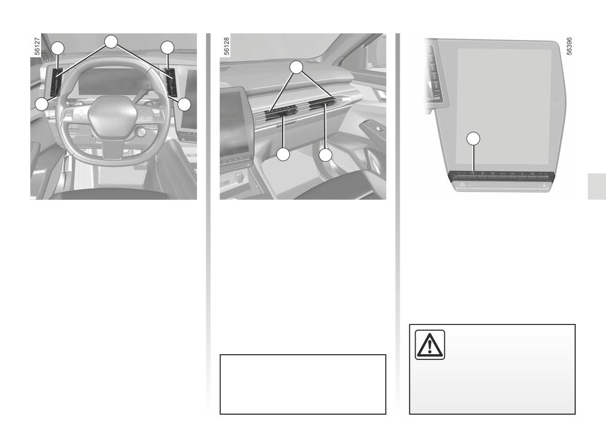
AIR VENTS, air outlets (2/3)
9
1
1
3
10
10
12
11
11
Driver’s position air vents 1
Passenger air vents 3
Air flow
To check the flow of the 1 and 3 air
Direction
Direction
vents, press or lift the 12 control ac-
To direct the air flow, turn the 1 air vents
To direct the air flow, turn the air vents
cording to the desired opening.
using the cursors 9.
using the cursors 11.
To remove bad odours from your ve-
hicles, only use the systems designed
To close: move the cursor 10 away
To close: move the cursor 11 towards
for this purpose. Consult an approved
from the steering wheel beyond the re-
the outside facade beyond the resist-
Dealer.
sistance point.
ance point.
To open: move the cursor 11 towards
To open: move the cursor 10 towards
the inside of the facade.
the steering wheel.
Do not add anything to the
vehicle’s ventilation circuit
(for example, to remove
bad odours).
Do not attach any objects to the air
vents (e.g. telephone mounting).
There is a risk of damage or of
fire.
Risk of damage.
3.5
AIR VENTS, air outlets (3/3)
7
13
Rear seats
(depending on the vehicle)
Direction
To direct the air flow, turn the air vents 7
using the cursors.
Do not attach any objects to the air
Air flow
vents (e.g. telephone mounting).
To check the flow of the air vents 7 turn
Risk of damage.
the knob 13 according to the desired
opening:
Do not add anything to the
- to the right: maximum air flow;
vehicle’s ventilation circuit
- to the left: closed.
(for example, to remove
bad odours).
There is a risk of damage or of
fire.
3.6
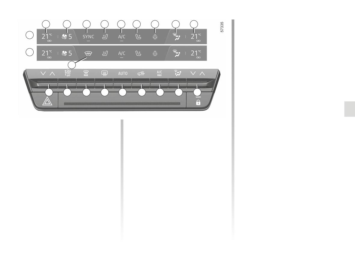
AUTOMATIC CLIMATE CONTROL (1/6)
14 Air-conditioning activation control in
1
2
3
4
5
6
7
8
9
AUTO mode.
A
15 De-icing/demisting of the rear screen
and, depending on the vehicle, the
rear view mirrors.
B
16 “Clear View” function.
19
17 Adjusting the ventilation speed and
stopping the system.
18 Driver’s air temperature setting and
SYNC “Synchronisation” function
18
17
16
15
14
13
12
11
10
activation control (configuration B).
19Heated windscreen activation con-
trol (configuration B).
The controls
7 Heated steering wheel activation
control.
1 Driver’s heating temperature indica-
tor.
8 Distribution of air in the passenger
compartment indicator.
2 Ventilation speed indicator.
9 Passenger heating temperature indi-
3 SYNC “Synchronisation” mode acti-
cator.
vation/deactivation control (configu-
ration A).
10 Adjusting the passenger’s air tem-
perature.
4 Driver’s heated seat activation con-
trol.
11 Passenger compartment air distribu-
tion adjustment.
5 Air-conditioning activation control.
12 Activation control for the “A/C MAX”
6 Passenger’s heated seat activation
function.
control.
13 Air recirculation.
3.7
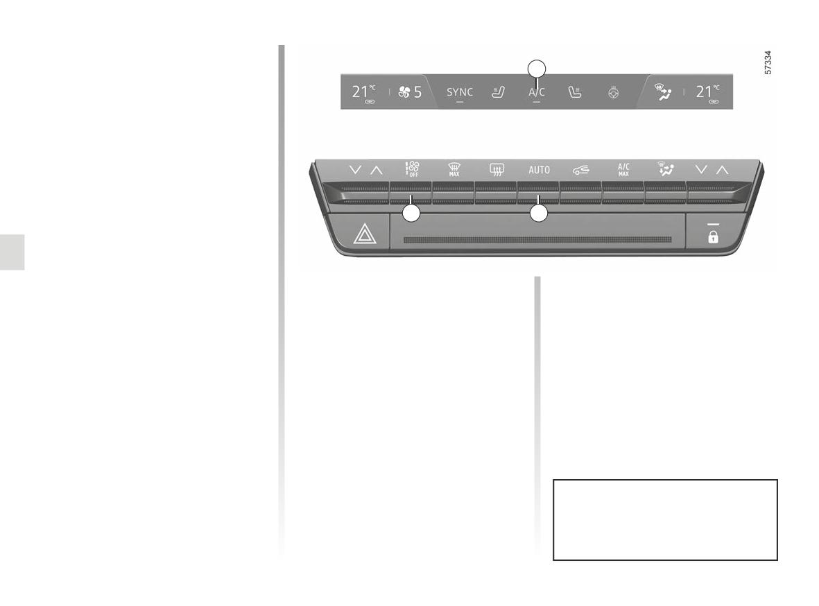
AUTOMATIC CLIMATE CONTROL (2/6)
Activating the system
When the vehicle is started, the system
5
returns to the last programme used.
Press the 14 control to activate the
system or set the 17 control to the de-
sired ventilation speed.
Stopping the system
Press the 17 control until it reaches the
“OFF" position.
17
14
Switching air conditioning on
or off
In automatic mode, the system man-
The system controls the ventilation
FAST: increases the flow of air in the
ages activation of the air conditioning. It
speed, air distribution, air recirculation,
passenger compartment. This mode
is still possible to activate or deactivate
and starting and stopping the air condi-
is recommended in particular to opti-
the system by pressing the 5 control.
tioning and air temperature.
mise comfort in the rear seats. Press
This mode consists of a choice of three
the 14 button, then press upwards to
programmes:
activate FAST mode.
Automatic mode
AUTO: allows the selected comfort
When the air conditioning starts in au-
The automatic climate control system
level to be best attained, depending on
tomatic mode, the system returns to the
guarantees comfort in the passenger
the exterior conditions. Press button 14.
last programme used.
compartment and good visibility (except
in the event of extreme conditions),
SOFT: reaches the desired comfort
while optimising fuel consumption.
level more gently and silently. Press
the 14 button, then press downwards to
activate SOFT mode.
Any action on a button other than
the AUTO button disables auto-
matic mode.
3.8
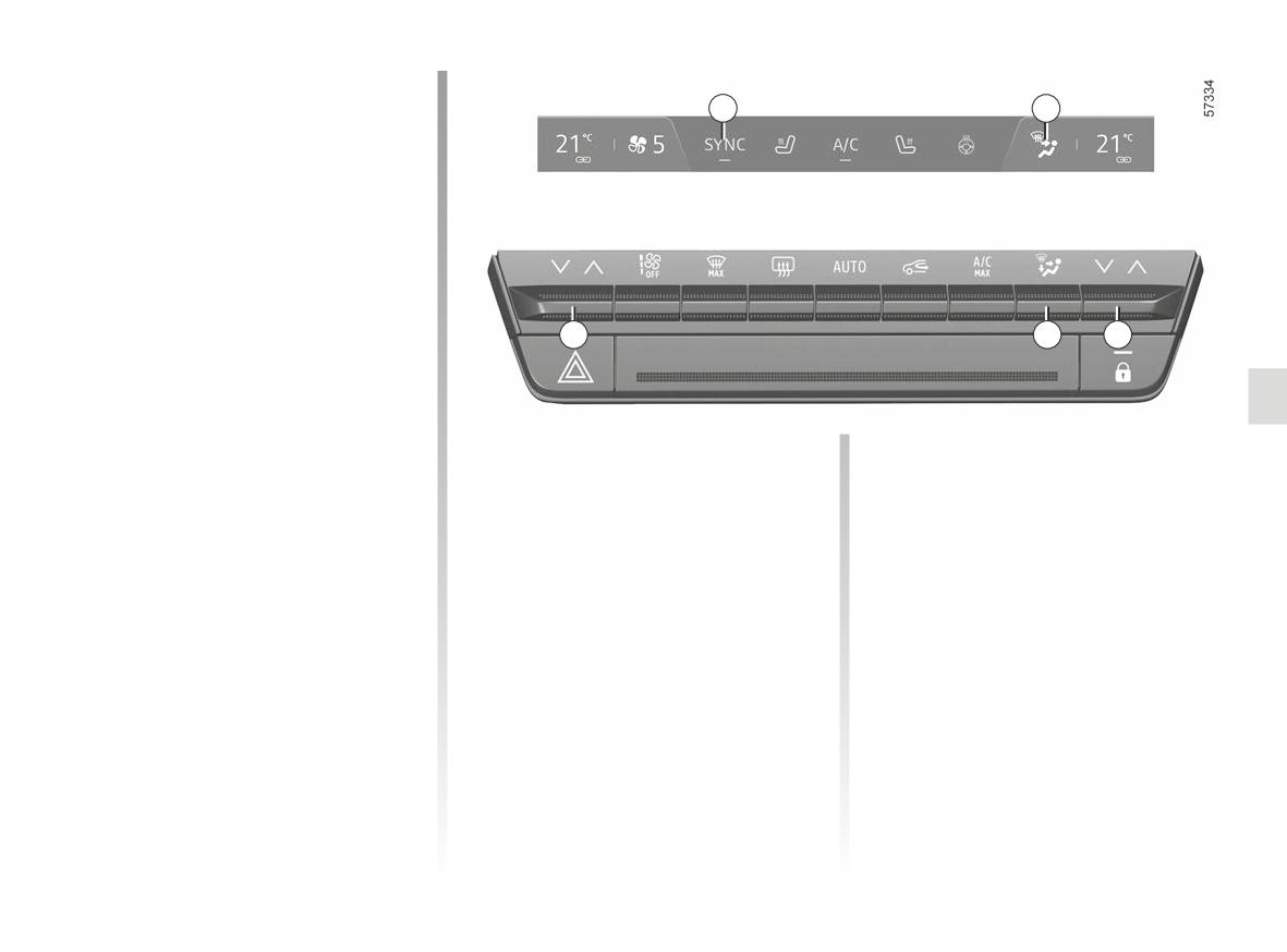
AUTOMATIC CLIMATE CONTROL (3/6)
Adjusting the distribution
of air in the passenger
3
8
compartment
Press 11 one or more times to select
the air distribution. The air distribution
selected 8 is displayed on the multime-
dia screen. The positions are in the fol-
lowing order:
All the air is then directed to
‚
the windscreen and front side
window demisting vents.
18
11
10
The air flow is distributed be-
tween front side window de-
misting vents, the windscreen demist-
ing vents and the footwells.
The air flow is directed towards
Independent adjustment of the
ö
the dashboard vents and to-
passenger compartment
The air flow is distributed be-
wards the footwells.
tween the front side window
Use the 10 and 18 controls to adjust
demisting vents, the windscreen de-
The air flow is directed mainly
the left-hand and right-hand sides inde-
misting vents, the dashboard air vents
ó
towards the footwells.
pendently.
and the footwells.
SYNC function setting
The air flow is mainly directed
Adjusting the air temperature
ô
to the dashboard air vents.
Press SYNC 3 on your multimedia
There are two types of settings:
screen or, depending on the vehicle,
- independent adjustment of the pas-
on the 10 or 18 control, then on SYNC
senger compartment;
to synchronise the passenger tempera-
ture with the driver's side.
- adjustment in SYNC mode to syn-
chronise the passenger's side and
To exit this function, press SYNC
the driver's side.
again or adjust the temperature on the
passenger side.
3.9
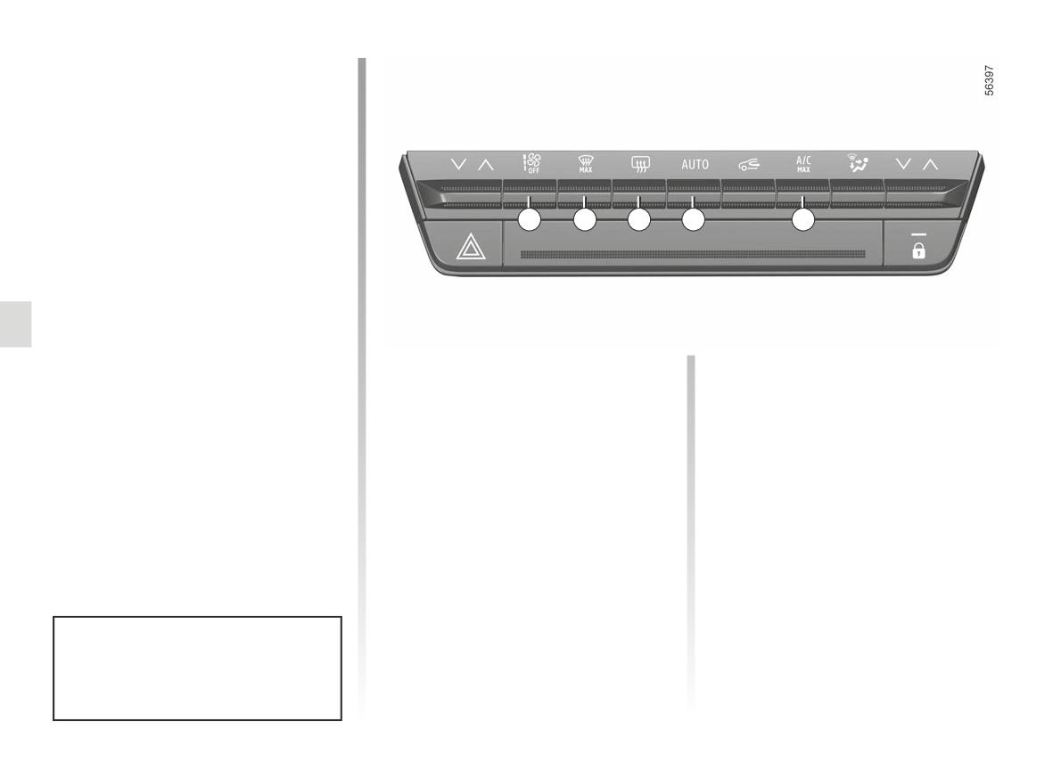
AUTOMATIC CLIMATE CONTROL (4/6)
Adjusting the ventilation
speed.
In automatic mode, the system uses
the most suitable amount of air to reach
and maintain the desired comfort level.
You can still adjust the ventilation speed
by pressing the 17 control to increase
or reduce the ventilation speed.
17
16
15
14
12
Clear View function
Press the 16 button: the integrated indi-
cator light comes on.
This function quickly de-mists the wind-
screen, rear screen, front side windows
Rear screen de-icing/
“A/C MAX” function
and door mirrors (depending on the
vehicle). The air conditioning and rear
demisting
The “A/C MAX” function enables the
screen de-icing functions must be ac-
Press the 15 button: the integrated in-
user to feel the maximum power of their
tivated.
dicator light comes on. This function
air conditioning system without any
enables rapid demisting or de-icing of
constraint or compromise related to
To exit this function, press button 14
the acoustics and the feeling of the air
the rear screen and de-icing of the rear
or 16.
view mirrors (on equipped vehicles).
being too cold on the hands and face.
To exit this function, press button 15
again. Demisting automatically stops.
Some buttons have an operating
tell-tale which indicates the operat-
ing status.
3.10
AUTOMATIC CLIMATE CONTROL (5/6)
Manual use
Press the 13 button: the integrated indi-
cator light comes on.
Prolonged use of this position may lead
to odours, caused by non-renewal of
air, and the formation of condensation
on the windows.
13
We therefore advise you to return to au-
tomatic mode as soon as air recircula-
tion is no longer needed, by pressing
button 13.
“A/C MAX” function
Air recirculation (isolation of
(continued)
the passenger compartment)
This function involves automatic mod-
This function is managed automatically,
ifications:
but you can also activate it manually. In
- temperature programmed to fully
this case the operation is confirmed by
cold;
a warning light on button 13).
- distribution of air to the occupants;
- air flow at its maximum power;
- activation of the air conditioning;
- air recirculation.
Press the 12 button to activate the func-
tion. Deactivate ECO mode to make the
most of it.
The demisting/de-icing will still take
priority over the air recirculation.
3.11
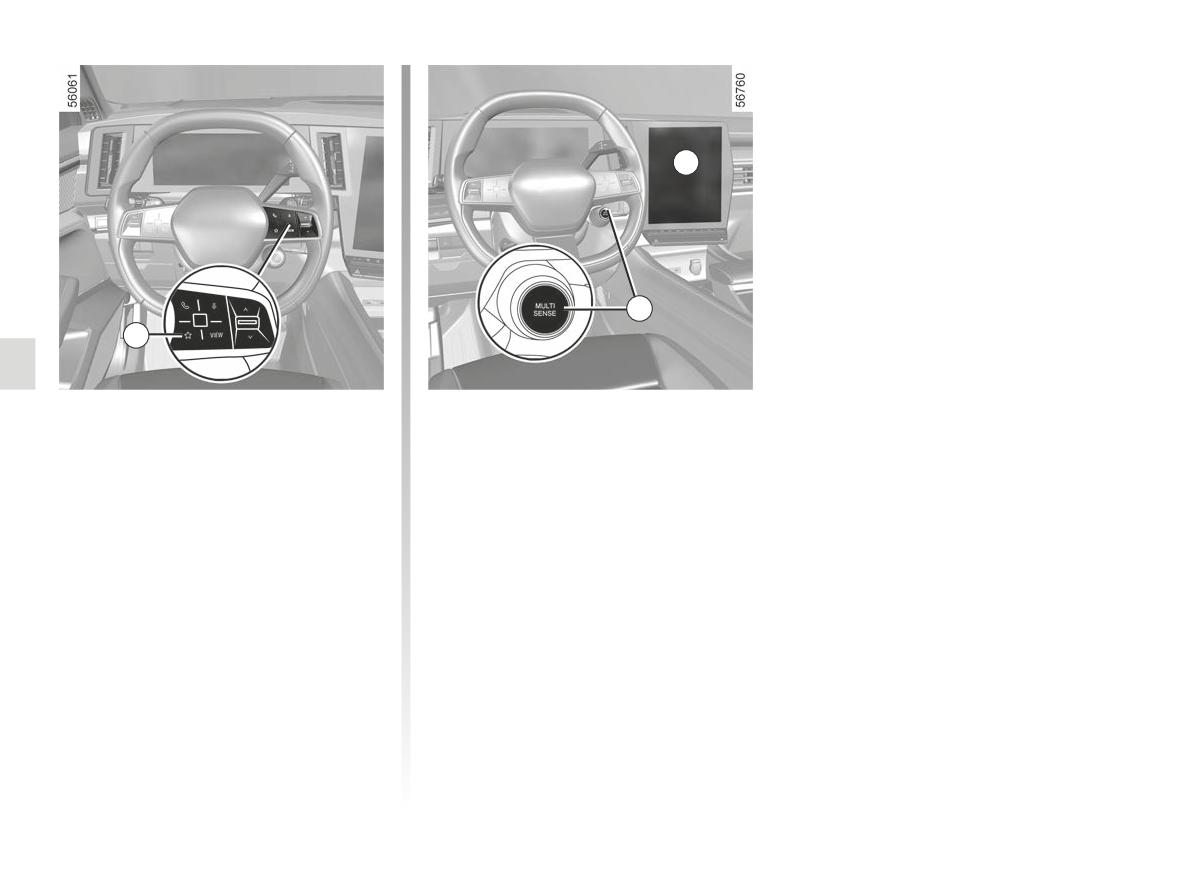
AUTOMATIC CLIMATE CONTROL (6/6)
21
22
20
“Favourites” function
ECO mode
Depending on the vehicle, by pressing
From the MULTI-SENSE menu acces-
the steering wheel control 20, you can
sible from the multimedia screen 21 or
activate the following functions accord-
by pressing the 22, switch, you can acti-
ing to the stored use settings that you
vate the ECO mode, which affects the
have previously defined:
heating level and reduces the vehicle's
fuel consumption.
- heated steering wheel;
A ECO warning light located under the
- heated seats.
temperature display on the multimedia
For more information on programming
screen 21 informs you that ECO mode
this function, please refer to the multi-
is activated.
media instructions.
3.12
AIR CONDITIONING: information and operating instructions (1/3)
Advice on use
Fuel consumption
Operating faults
In some situations (air conditioning off,
You will normally notice an increase in
As a general rule, contact your ap-
air recirculation activated, ventilation
fuel consumption (especially in town)
proved dealer in the event of an oper-
speed at zero or low etc.), you may
when the air conditioning is operating.
ating fault.
notice that condensation starts to form
For vehicles fitted with air conditioning
- Reduction in de-icing, demisting
on the windows and windscreen.
with no automatic mode, switch off the
or air conditioning performance.
system when it is not required.
If there is condensation, use the “Clear
This may be caused by the passen-
View” function to remove it, then use
ger compartment filter cartridge be-
Advice for reducing consumption
the air conditioning in automatic mode
coming clogged.
and helping to preserve the
to stop it forming again.
environment
- No cold air is being produced.
Check that the controls are set cor-
Drive with the air vents open and the
rectly and that the fuses are sound.
windows closed. If the vehicle has been
Otherwise, switch off the system.
parked in the sun, open the doors for a
few moments to let the hot air escape
before starting the engine.
Presence of water under the
vehicle
Maintenance
After prolonged use of the air condi-
Refer to the Maintenance Document
tioning system, it is normal for water
Vehicles equipped with
for your vehicle for the inspection fre-
to be present under the vehicle. This is
mode ECO
quency.
caused by condensation.
Once activated, ECO mode may
reduce air conditioning perfor-
mance ➥ 2.29.
Do not add anything to the
vehicle’s ventilation circuit
Do not open the refriger-
(for example, to remove
Use the air conditioning system reg-
ant fluid circuit. The fluid
bad odours).
ularly, even in cold weather, running
may damage eyes or skin.
There is a risk of damage or of
it at least once a month for approxi-
fire.
mately 5 minutes.
3.13
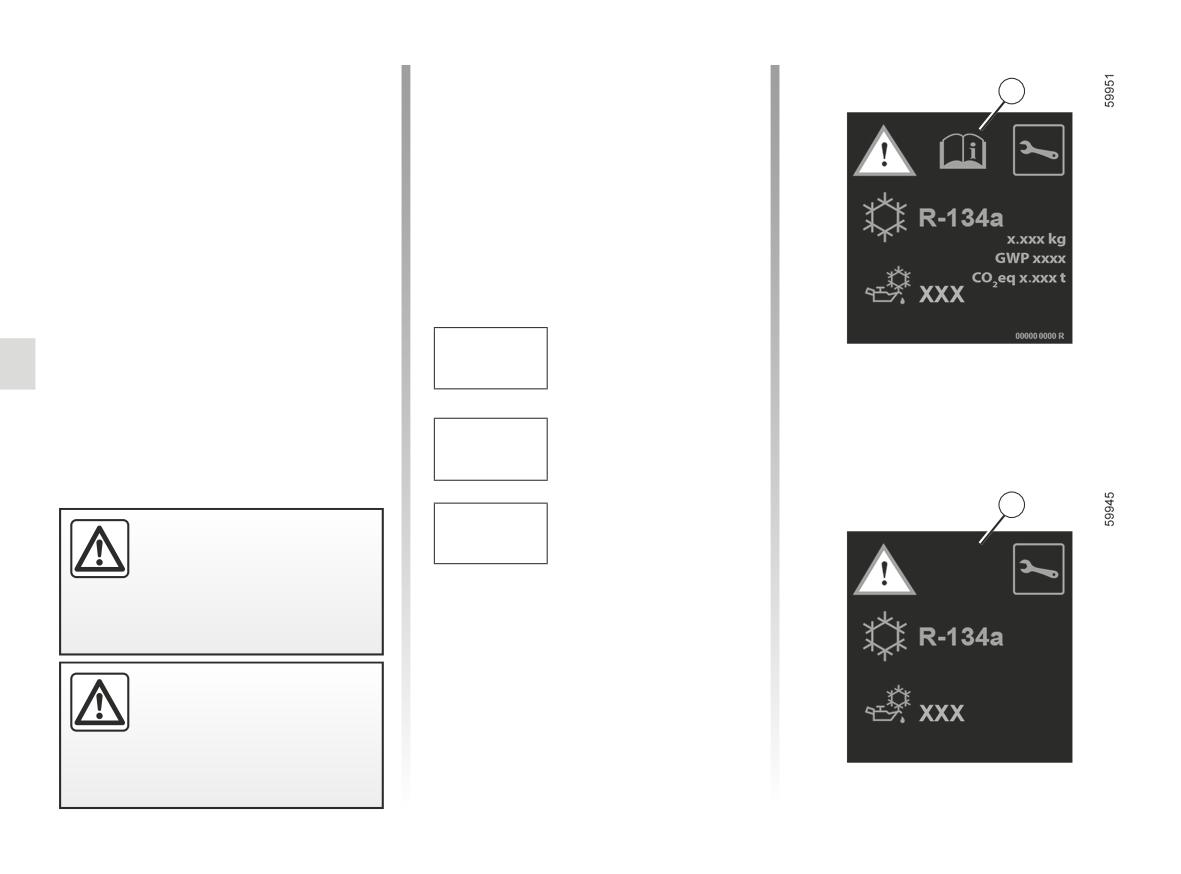
AIR CONDITIONING: information and operating instructions (2/3)
The refrigerant fluid circuit (of which
Type of refrigerant fluid
some components are hermetically
Ñ
A
sealed) contains fluorinated green-
(XXX) Type of oil in the air
house gases.
conditioning circuit
Inflammable product
Refrigerant fluid R-134a
Depending on the vehicle, you will find
Consult the driver’s hand-
the following information on label A af-
book
fixed inside the engine compartment.
Maintenance
The presence and location of the infor-
mation on label A depends on the ve-
hicle.
Quantity of refrigerant
x.xxx kg
fluid present in the ve-
hicle.
Global
Warming
GWP xxxxx
Potential (CO2 equi-
valent).
A
CO2 eq
Quantity in weight and
Do not open the refriger-
x.xxt
in CO2 equivalent.
ant circuit. The fluid may
damage eyes or skin.
Before carrying out any
action in the engine com-
partment, you must switch
off the ignition. ➥ 2.3.
3.14
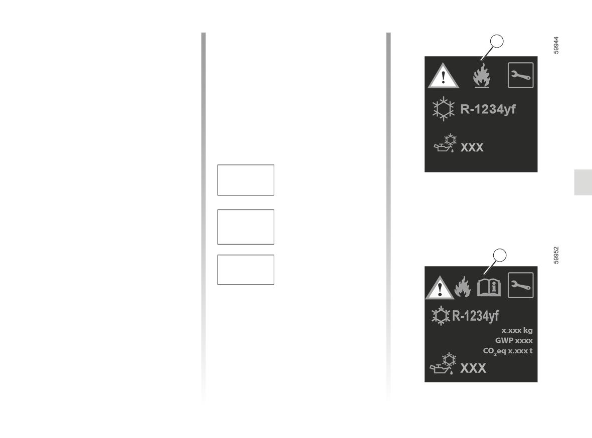
AIR CONDITIONING: information and operating instructions (3/3)
Refrigerant fluid R-1234yf
Type of refrigerant fluid
Ñ
B
Depending on the vehicle, you will find
the following information on label B af-
(XXX) Type of oil in the air conditioning circuit
fixed inside the engine compartment.
The presence and location of the infor-
Inflammable product
mation on label B depends on the ve-
hicle.
Consult the driver’s hand-
book
Maintenance
Quantity of refrigerant
fluid present in the ve-
x.xxx kg
hicle.
Global
Warming
Potential (CO2 equi-
GWP xxxxx
valent).
B
CO2 eq
Quantity in weight and
x.xxt
in CO2 equivalent.
3.15
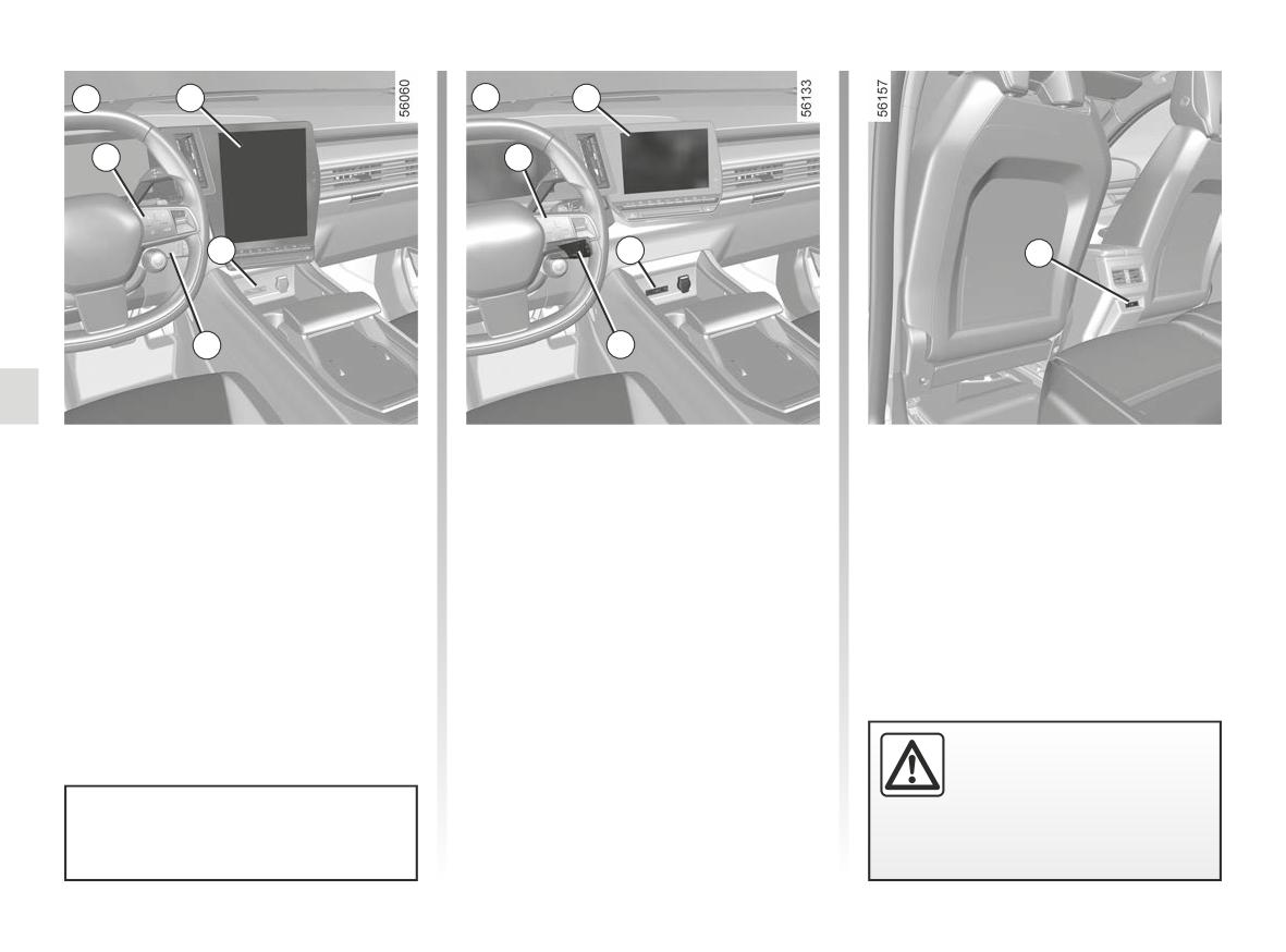
MULTIMEDIA EQUIPMENT (1/2)
A
1
B
1
4
4
2
2
5
3
3
Multimedia screen A, B
Multimedia “USB-C” 2 and 5
The location and operation of equip-
ports
ment may vary according to the vehicle.
The multimedia USB-C 2 and 5 ports
1 Multimedia screen.
enable accessories approved by our
2 Two multimedia USB-C ports in the
Technical Department to be recharged,
centre console.
providing the power does not exceed
3 Steering column control.
15 watts (5 V) per socket.
4 Phone control.
Note: the multimedia USB-C 2 ports
5 Two multimedia USB-C ports.
also allow for data transfer.
Connect accessories with
a maximum power of 15
Watts only.
Please refer to the multimedia in-
Fire hazard.
structions for further information.
3.16
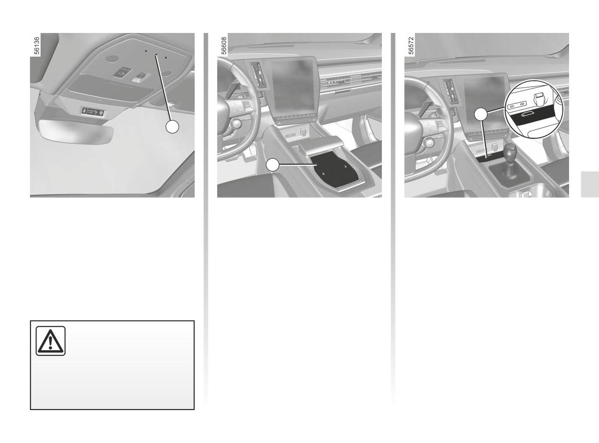
MULTIMEDIA EQUIPMENT (2/2)
8
6
7
Microphone 6
Wireless charger 7
Wireless charger 8
(for the phone and voice assistant)
(for vehicles equipped with an auto-
(for vehicles equipped with a manual
matic gearbox) ➥ 3.24
gearbox) ➥ 3.24
Using the telephone
We remind you of the need
to conform to the legislation
in force concerning the use
of such equipment.
3.17
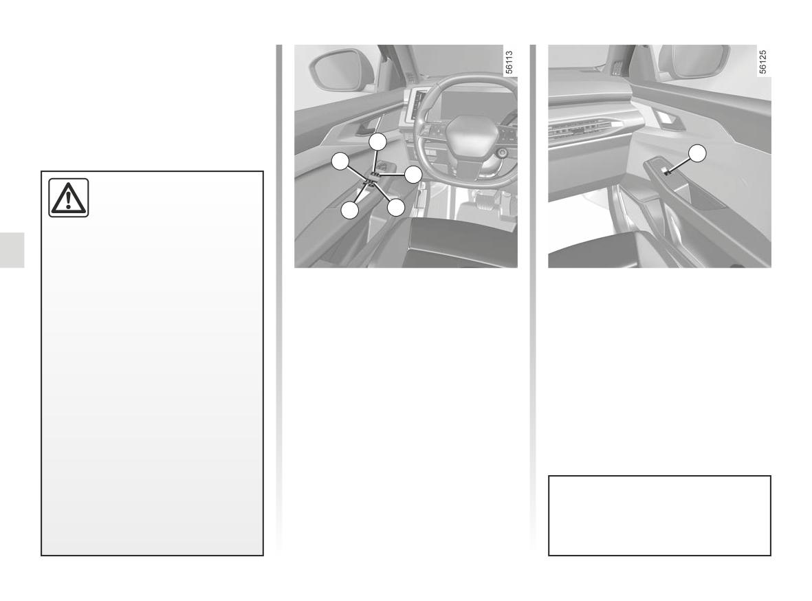
ELECTRIC WINDOWS (1/2)
These systems operate with the igni-
tion on or off, until one of the front doors
is opened (limited to about 3 minutes).
1
6
5
2
Driver’s responsibility
Never leave your vehicle
3
4
with the card or key inside,
with a child, adult who is not
self-sufficient or a pet in the vehicle,
even for a short while.
They may pose a risk to themselves
One-touch electric windows
Note: following the locking of the rear
or to others by starting the engine
Briefly press or pull a window switch
windows, the message “Rear Electric
or activating equipment (such as the
as far as it will go: the window will be
Windows Locked” appears on the in-
gear lever or electric windows).
raised or lowered fully. Pressing the
strument panel.
switch again stops the window moving.
From the passenger seat, move
If any part of the body becomes
Note: the rear windows do not open
switch 6.
trapped, reverse the direction of the
fully.
window immediately by pressing the
relevant switch.
From the driver’s seat, use switch:
1
for the driver’s side;
Risk of serious injury.
2
for the front passenger side;
3
and 5 for the rear passengers;
4
to lock the rear windows.
Avoid resting any objects against
a half-open window: there is a risk
that the electric window could be
damaged.
3.18
ELECTRIC WINDOWS (2/2)
One-touch electric windows
Remote control window
Operating faults
(continued)
opening/closing
In case of a fault when closing a
Note: if the window detects resistance
When unlocking the doors from the out-
window, the system reverts to normal
when closing (e.g. tree branch etc.), it
side, if you press and hold the card
mode: pull the switch concerned up as
stops and then lowers again by a few
unlocking button, all the windows
often as necessary to fully close the
centimetres.
equipped with a one-touch electric
window (the window will close gradu-
window will open automatically.
ally), hold the switch (still on the clos-
ing side) for one second then lower and
Impossible to operate the
When locking the doors from the out-
raise the window fully to reinitialise the
side, if you press and hold the card
one-touch electric window
system.
locking button, all the windows
The one-touch electric window is
equipped with a one-touch electric
If necessary, contact an approved
equipped with heat protection: if you
window will close automatically.
Dealer.
press the switch for the window more
It is recommended that the user only
than 16 consecutive times it goes into
operates the system when the vehi-
protection mode (locking the window).
cle can be seen clearly and no one is
You can:
inside.
- use the electric window switch briefly
and with intervals of approximately
30 seconds;
- with the engine running, the window
will be unlocked after approximately
20 minutes of inaction on the electric
Passenger safety
window switch.
The driver can prevent the
front and rear passenger
When closing the windows,
electric windows from op-
ensure that no part of the
erating (and the driver’s window)
body (arm, hand, etc.) is
by pressing switch 4. A confirmation
protruding from the vehicle.
message is displayed on the instru-
ment panel.
Risk of serious injury.
3.19
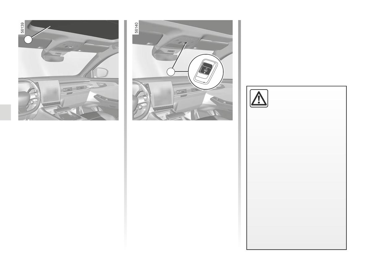
FIXED GLASS ROOF
1
2
Driver’s responsibility
Never leave your vehicle
with the card or key inside
when there is a child, de-
pendent adult or a pet in it, even for
Sun blind 1
Special features
a short while.
(depending on the vehicle)
If the fixed sunroof blind detects resist-
They may pose a risk to themselves
ance when closing (arm etc.), it stops
or to others by starting the engine,
To slide the sunroof
and then moves back several centime-
activating equipment such as the
- To open: push the button 2 back-
tres.
electric windows or by locking the
wards to move the blind to the de-
doors.
sired position. A short push back-
Operating fault
If something gets caught, immedi-
wards opens the blind completely.
ately reverse the direction of travel
If the blind 1 does not close, push the
- To close: push the button 2 forwards
using the button 2.
button 2 backwards to open the blind 1,
to move the blind to the desired po-
then push the 2 button forwards until
Risk of serious injury.
sition. A short push forwards closes
the blind is fully closed.
the blind completely.
If the blockage persists, contact an ap-
proved dealer.
3.20
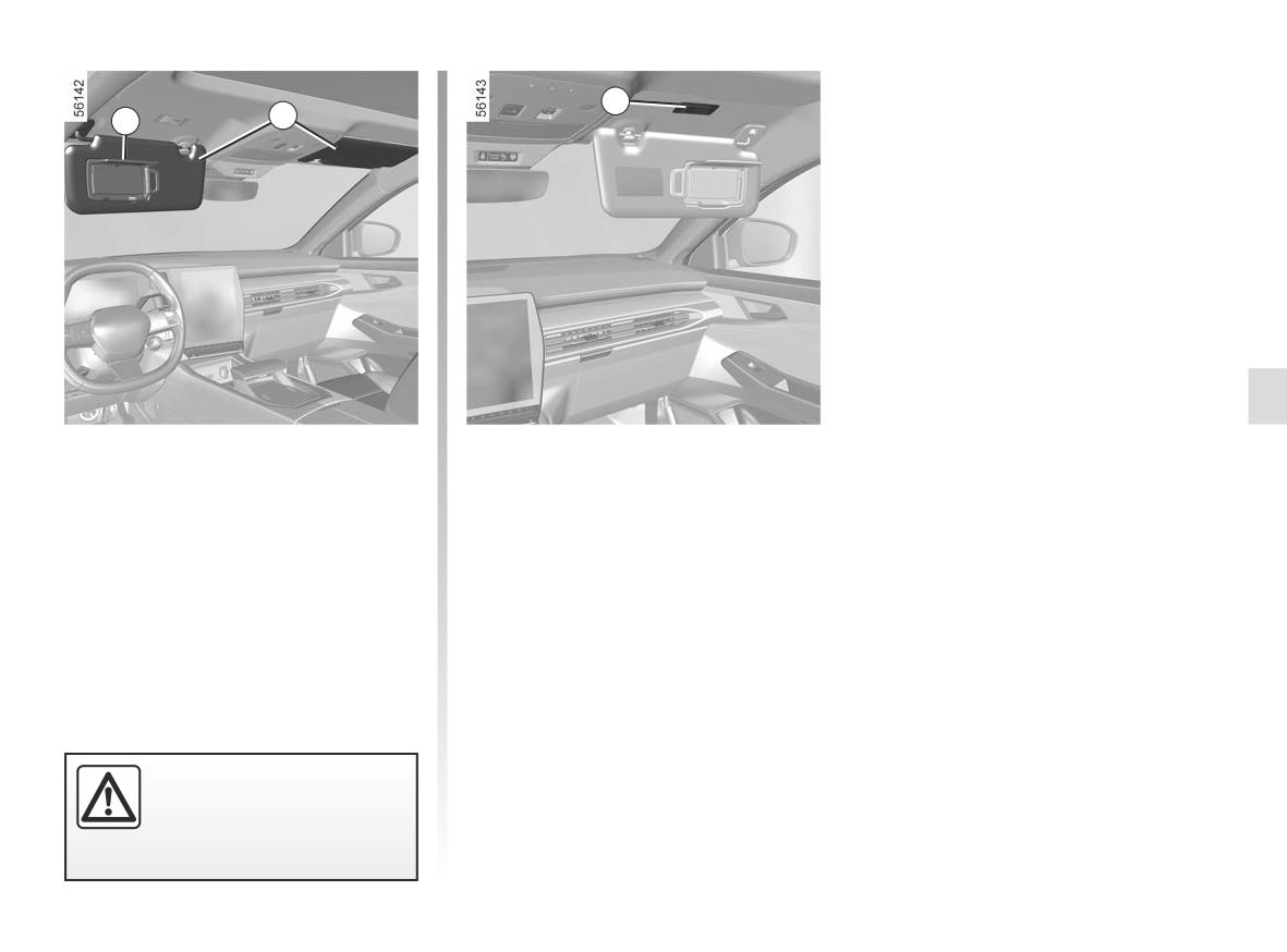
SUN VISOR
3
2
1
Front sun visor
Lower sun visor 2.
Courtesy mirrors
(depending on the vehicle)
Lift the cover 1. The light 3 switches on
automatically.
When driving, ensure the
courtesy mirror cover is
closed.
Risk of injury.
3.21
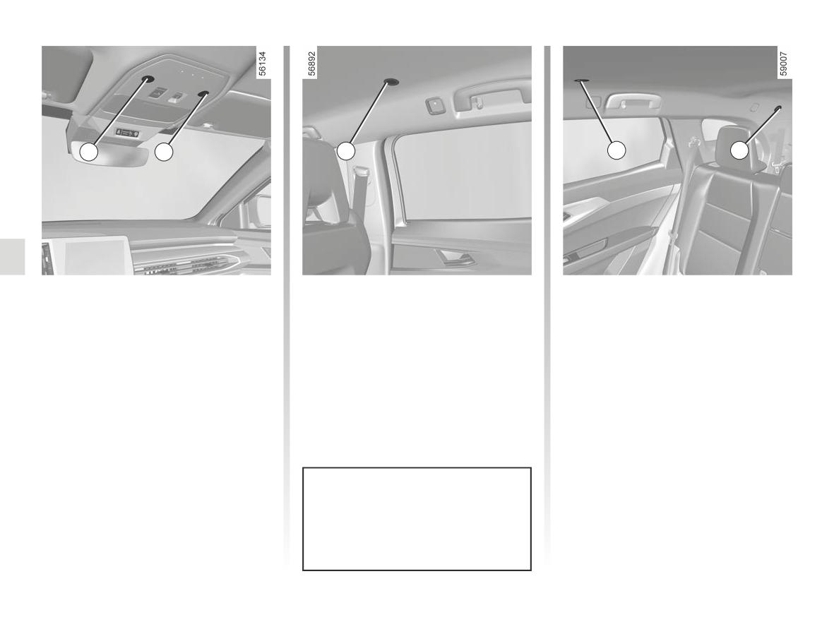
INTERIOR LIGHTING (1/2)
1
2
3
3
4
Reading lights
Depending on the vehicle, the 3 light is
complemented by the 4 light.
Touch lights 1, 2, 3 or 4 to activate:
- permanent lighting;
- lighting switches off immediately.
Note:
- It is not necessary to press the lights
to activate or deactivate the lighting.
You only need to make contact;
- from the multimedia screen you
can deactivate/activate the reading
lights coming on when the doors are
opened ➥ 1.91.
Unlocking and opening the doors or
tailgate switches on the timed cour-
tesy lights and lights.
3.22

INTERIOR LIGHTING (2/2)
5
Luggage compartment light
Light 5 comes on when the luggage
compartment is opened.
Unlocking and opening the doors or
tailgate switches on the timed cour-
tesy lights and lights.
3.23
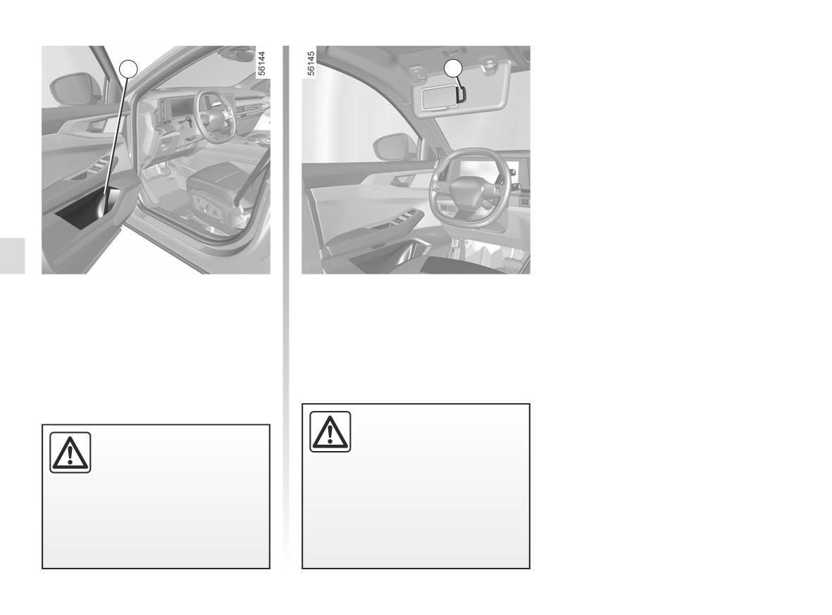
PASSENGER COMPARTMENT STORAGE, FITTINGS (1/6)
1
2
Front door storage pockets 1
Sun blind storage
They can hold a 1.5-litre bottle.
compartment 2
This can be used for storing motorway
tickets, cards, etc.
Ensure that no hard, heavy
or pointed objects are
Nothing should be placed
placed in the “open” storage
on the floor area in front of
compartments in such a
the driver as such objects
way that they may fall onto passen-
may slide under the pedal
gers during sudden turning, braking
during braking manoeuvres, thus
or if the airbags are deployed.
obstructing its use.
3.24
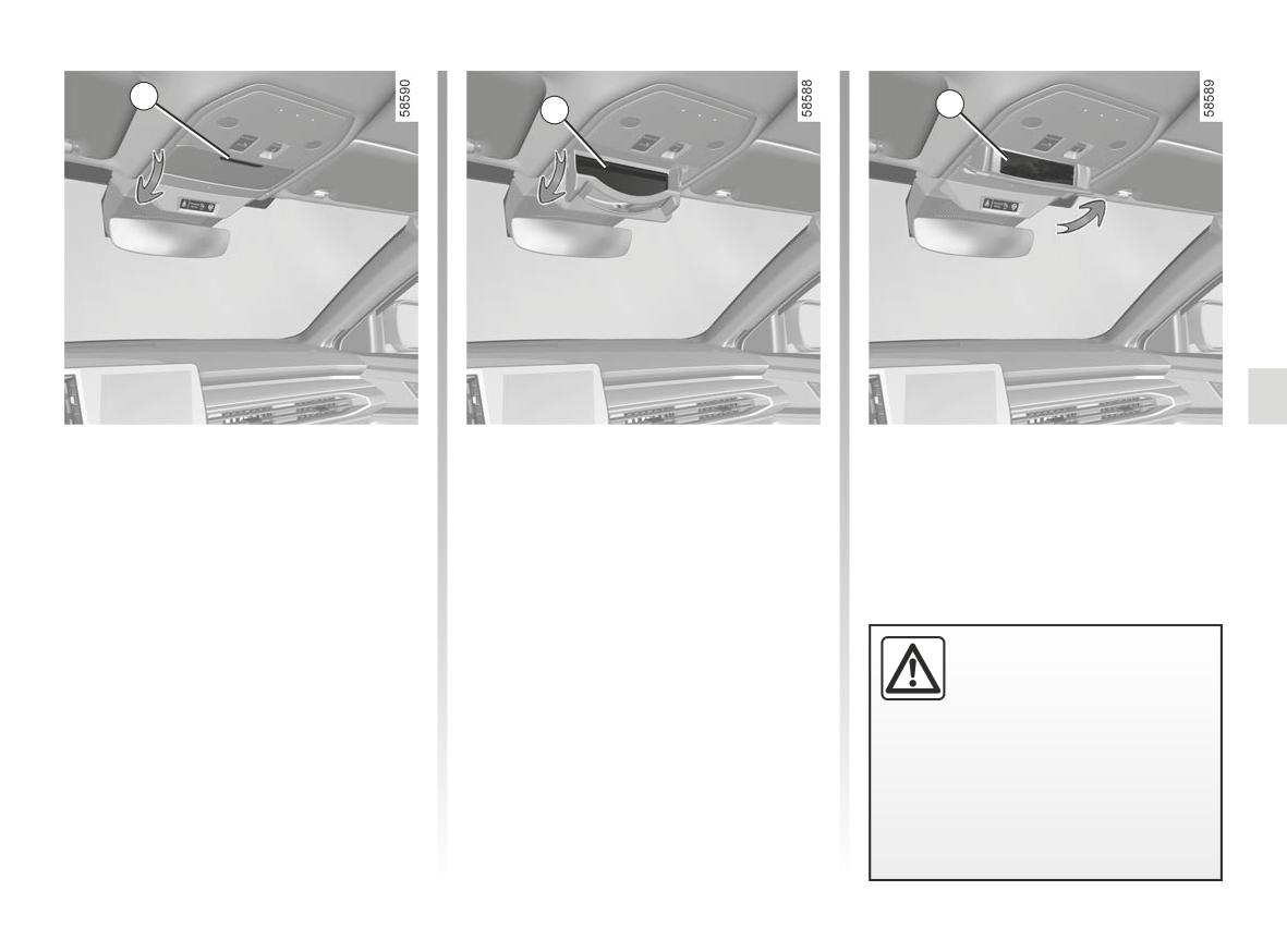
PASSENGER COMPARTMENT STORAGE, FITTINGS (2/6)
3
5
4
Sunglasses holder 4
Child minder mirror 5
Press area 3 to open the sunglasses
To access the child minder mirror, open
holder.
the sunglasses holder 4, then close it to
its intermediate position.
Ensure that no hard, heavy
or pointed objects are
placed in the “open” storage
compartments in such a
way that they may fall onto passen-
gers during sudden turning, braking
or if the airbags are deployed.
3.25
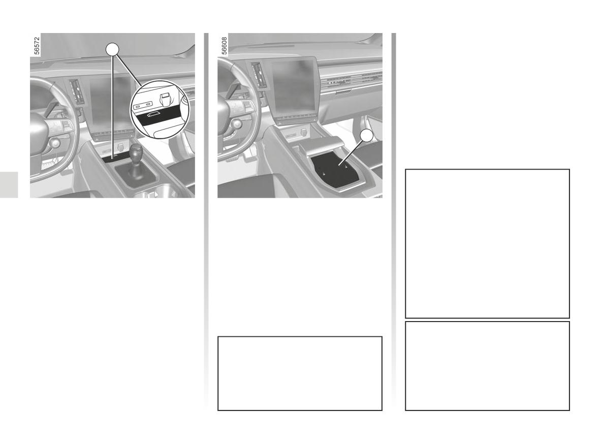
PASSENGER COMPARTMENT STORAGE, FITTINGS (3/6)
6
7
It is essential not to leave any ob-
Centre console storage
jects (start card, USB drive, SD
compartment or induction
card, credit card, jewels, keys,
charging area 6 or 7
coins, etc.) in the induction charg-
(depending on the vehicle)
ing area 6 or 7 when charging your
phone. Remove all magnetic cards
For more information on the induction
or credit cards from the phone case
charging zone, please refer to the mul-
before positioning your phone in the
timedia instructions.
induction charging area 6 or 7.
Objects left in the induction charging
Depending on the country and the
area 6 or 7 may overheat. You are
subscription, the induction charging
advised to place them in the areas
area 6 or 7 is also the placement
provided for this purpose (storage
area for smartphones equipped with
compartment, sun visor compart-
a digital key ➥ 1.21.
ment etc.).
3.26
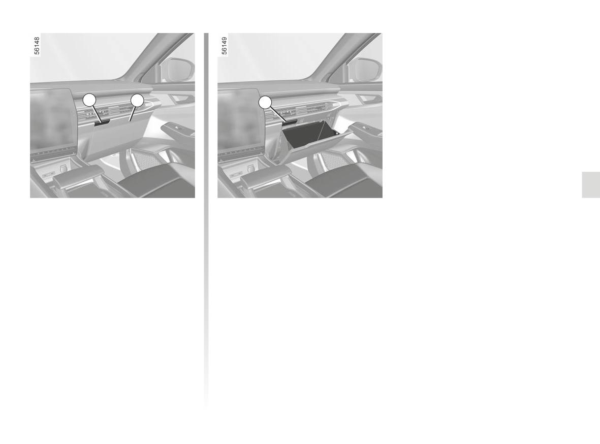
PASSENGER COMPARTMENT STORAGE, FITTINGS (4/6)
8
9
8
Passenger storage drawer 9
To open, press button 8.
3.27
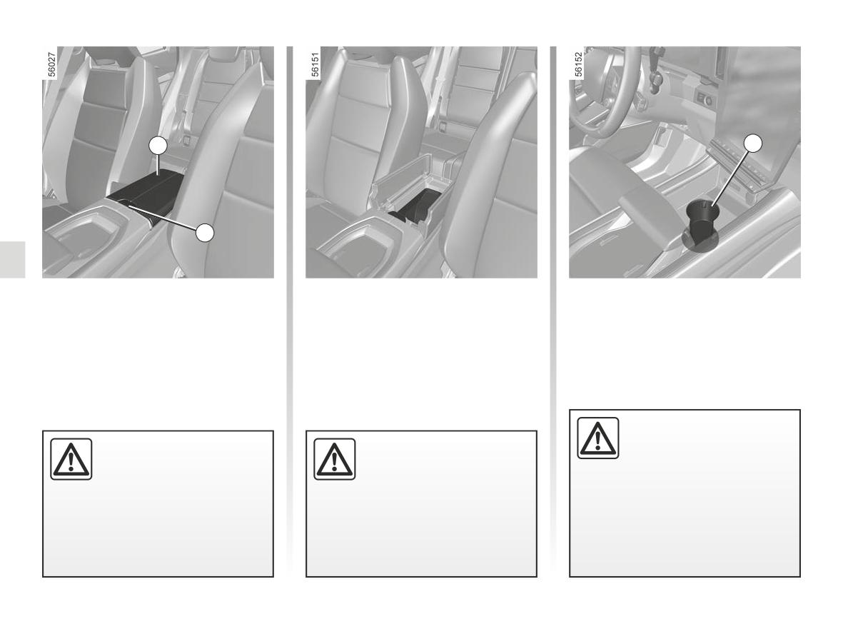
PASSENGER COMPARTMENT STORAGE, FITTINGS (5/6)
10
12
11
Centre armrest storage
Cup holders 12
compartment
Depending on the vehicle, the cup
Open the cover 10 of the central arm-
holder may be equipped with retaining
rest by pressing the 11 button.
hooks to keep the cup in place.
This can be used to store a mobile ash-
tray, drink cans, etc.
When turning corners,
accelerating or braking,
Do not place any objects on
Do not drive with the central
ensure that the recepta-
the central armrest storage
armrest in the open position
cle being held by the cup
compartment as this could
as this could hinder the op-
holder is not dislodged.
hinder the operation of
eration of the central airbag
the side airbag and/or cause injury
and/or cause injury when it is de-
There is a risk of injury if hot
when it is deployed.
ployed.
liquid escapes.
3.28
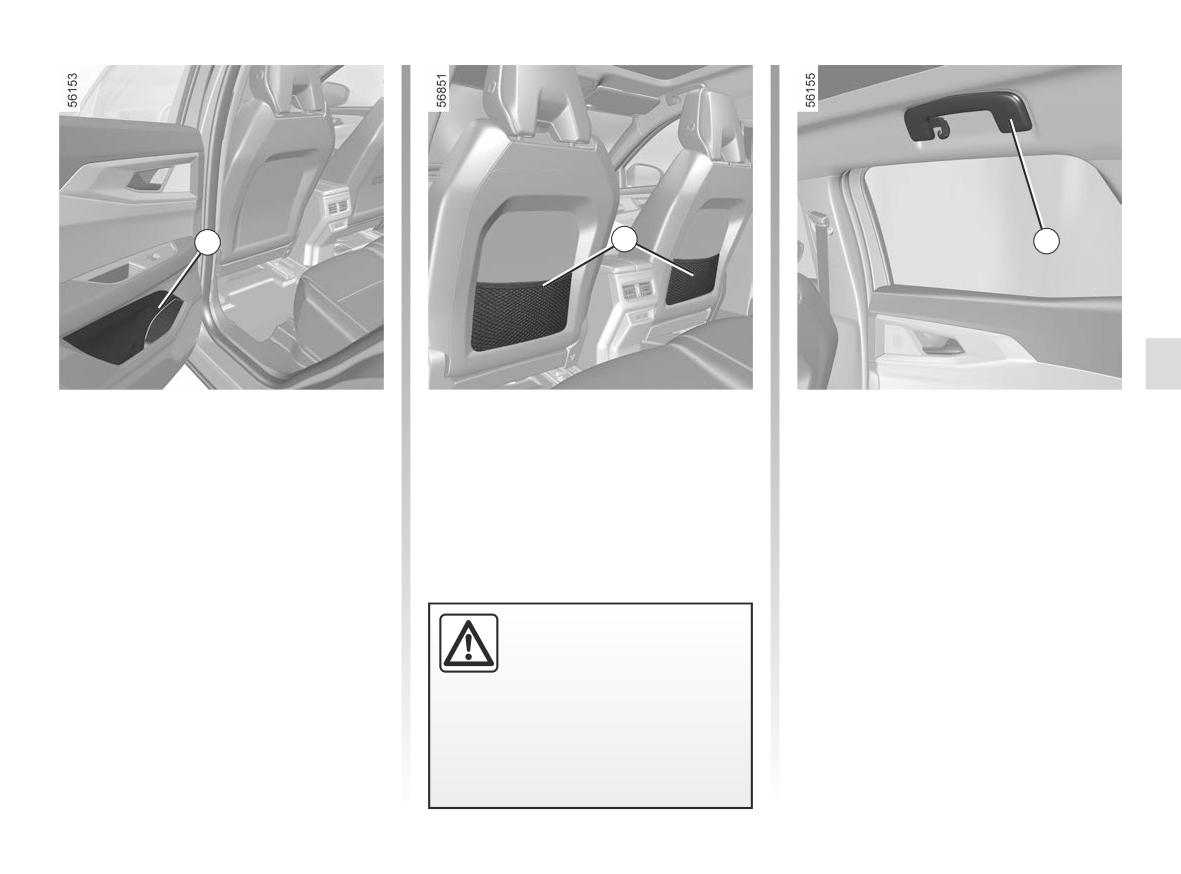
PASSENGER COMPARTMENT STORAGE, FITTINGS (6/6)
13
14
15
Rear door storage
Rear seat storage nets 14
Grab handle 15
compartment 13
(depending on the vehicle)
This offers support and can be held
They may receive a 0.11 gal (0.5 litre)
when the vehicle is moving.
bottle or a 0.22 gal (1 litre) bottle, de-
You can use it to get into or out of the
pending on the vehicle.
vehicle.
Ensure that no hard, heavy
or pointed objects are
placed in the “open” storage
compartments in such a
way that they may fall onto passen-
gers during sudden turning, braking
or in the event of an accident.
3.29
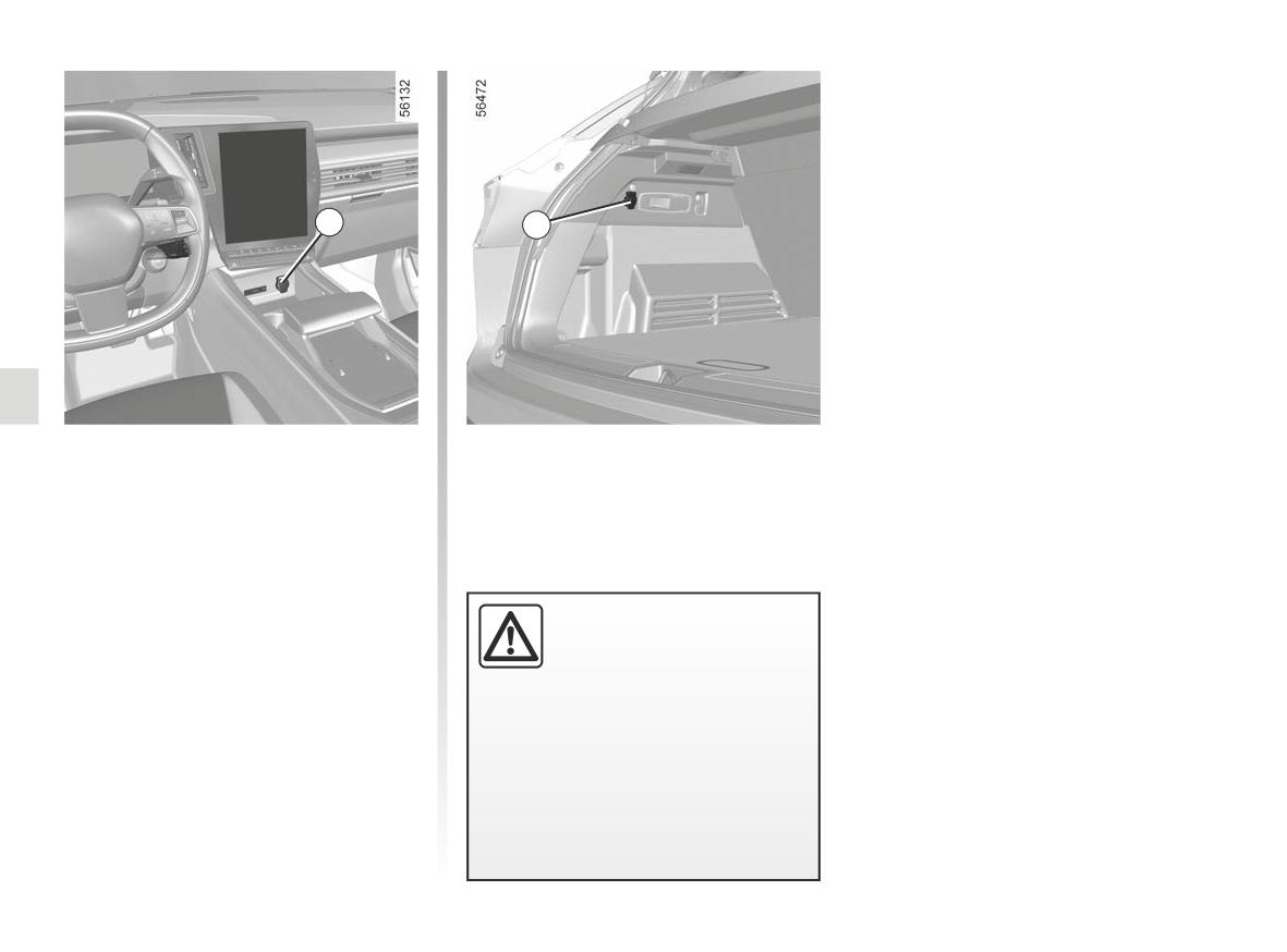
ACCESSORIES SOCKET
1
1
Accessories sockets 1
You can use the accessories sockets 1
to connect accessories approved by
our Technical Department.
Connect accessories with
a maximum power of 120
Watts (12 V) only.
When several accessory
sockets are used at the same time,
the total power of the connected
accessories must not exceed
180 watts.
Fire hazard.
3.30
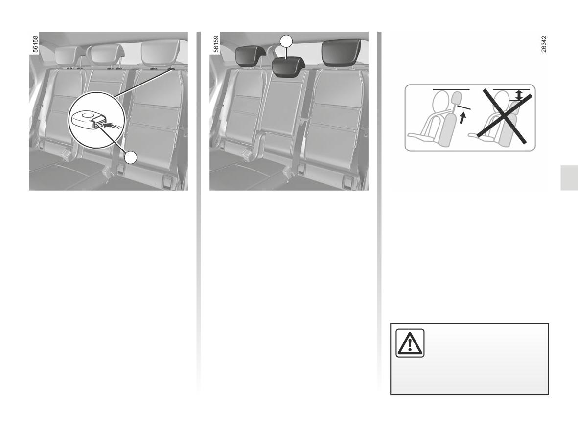
REAR HEADRESTS
2
1
Position for use
To refit the headrest
When the headrest is set at the
lowest position, this is for storage
Lift the headrest fully until it locks.
Fit the rods into their housing and push
only. It should not be in this position
down the headrest until it locks to set
Check that the bonnet is correctly
when a seat is occupied.
locked.
it to raised position. Check that the
bonnet is correctly locked.
To remove the headrest
Storage position 2 for the
Raise the headrest as far as it will go,
headrest
then press button 1 and remove the
headrest.
Press the button 1 and lower the head-
rest completely.
The headrest is a safety
component; check that it is
fitted and in the correct po-
sition.
3.31
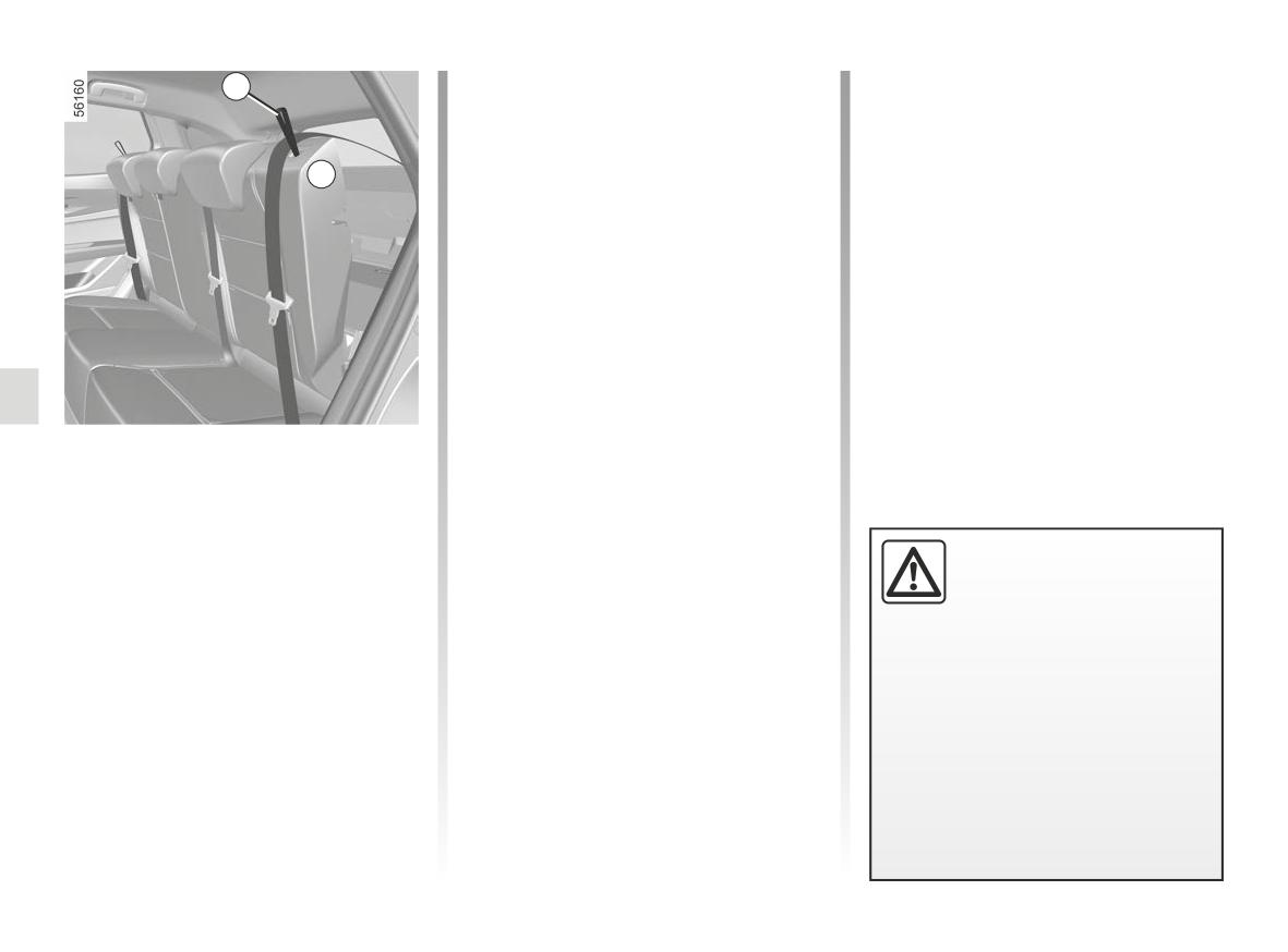
REAR BENCH SEAT: functions (1/3)
pull the strap 1 and lower the seat-
1
back A.
To replace the seatback, proceed in
the reverse order to removal.
A
Raise the seatback again until it
reaches the locking joint of the seat-
back. Be careful not to jam the seat belt
between the seatback and the parcel
shelf.
Check the operation of the seat belt.
Fixed bench seat
To fold down the seatback
Ensure that the front seats are far
enough forward.
When refitting the seat-
Before folding down a seatback:
back, make sure it is cor-
rectly locked in place.
- lower the headrests fully;
If seat covers are fitted,
- fasten the seat belt. This prevents
make sure these do not prevent the
the seat belt from locking when the
seatback latch from locking in.
seatback is lifted up again.
Make sure that the seat belts are
positioned correctly.
Reposition the headrests.
3.32
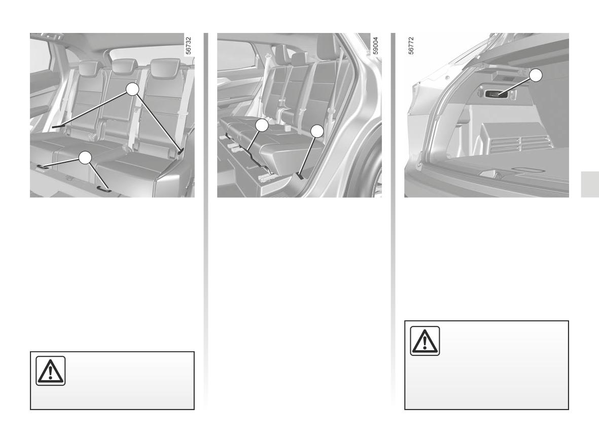
REAR BENCH SEAT: functions (2/3)
4
2
3
2
3
Sliding bench seat
To tilt the seatback (three possible po-
(depending on the vehicle)
sitions), pull the handle 5.
To unlock the bench seat, lift the
To fold down the seatback, pull the
lever 3.
strap 2 or pull the handle 4 located in
the luggage compartment. The seat-
Move the seat forwards or back to the
back folds itself down.
required position.
Release the lever 3 and ensure that the
bench seat is properly locked.
When moving the rear
seats, ensure that nothing
obstructs the anchorage
For safety reasons, carry
points (passenger’s arm or
out any adjustments when
leg, a pet, gravel, cloth, toys, etc.).
the vehicle is not being
driven.
3.33
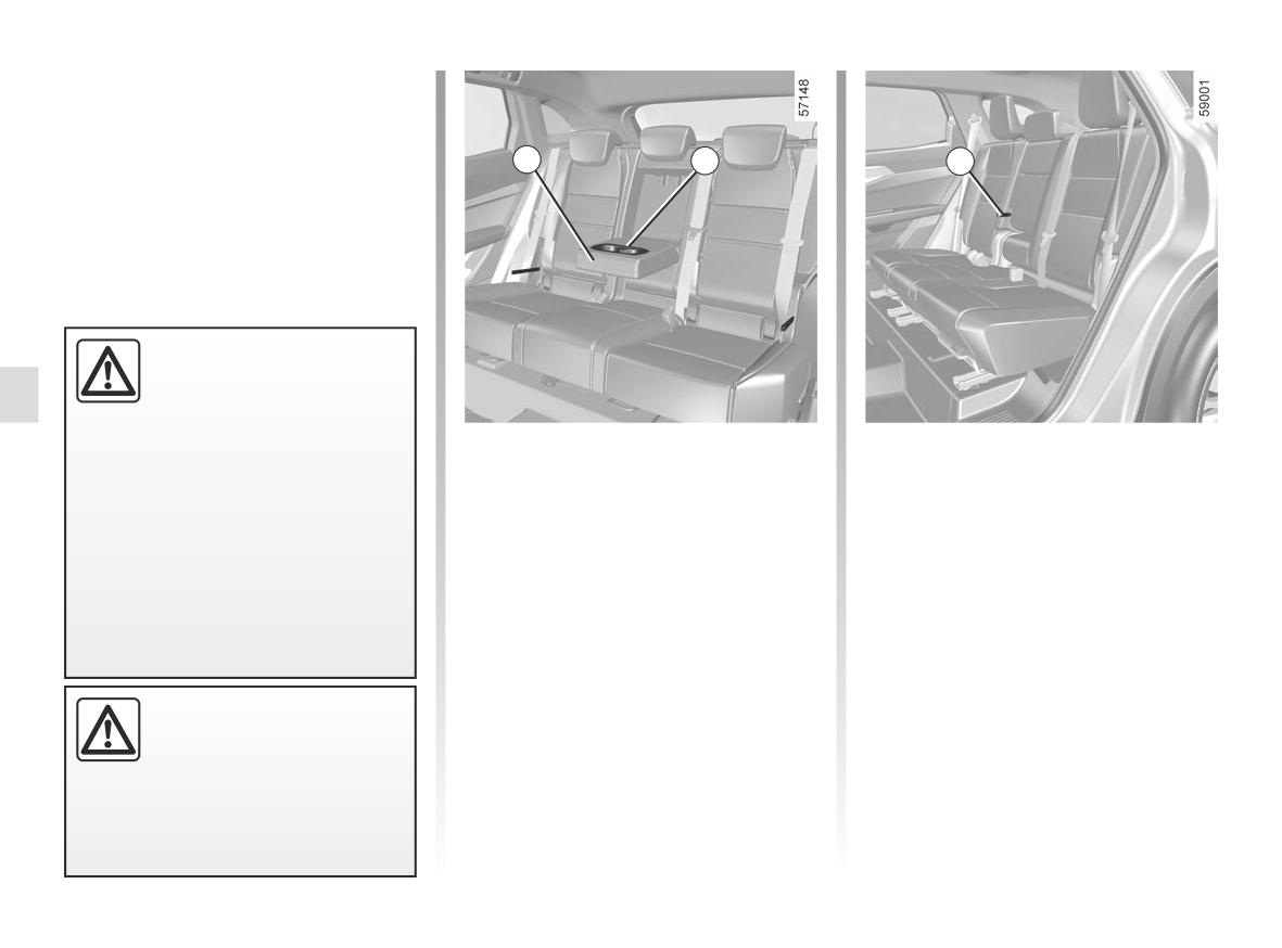
REAR BENCH SEAT: functions (3/3)
Use restriction
It is not permitted to drive with a second
row rear seatback or seat folded down
when there is a passenger occupying a
5
6
7
third row rear seat.
When refitting the seat-
back, make sure it is cor-
rectly locked in place.
If seat covers are fitted,
Central rear armrest
make sure these do not prevent the
(depending on the vehicle)
seatback latch from locking in.
Lower the central rear armrest 5 or, de-
Make sure that the seat belts are
pending on the vehicle, pull the strap 7.
positioned correctly.
The rear central armrest 5 is equipped
Reposition the headrests.
with two cup holders 6.
When moving the rear
seats, ensure that nothing
obstructs the anchorage
points (passenger’s arm or
leg, a pet, gravel, cloth, toys, etc.).
3.34
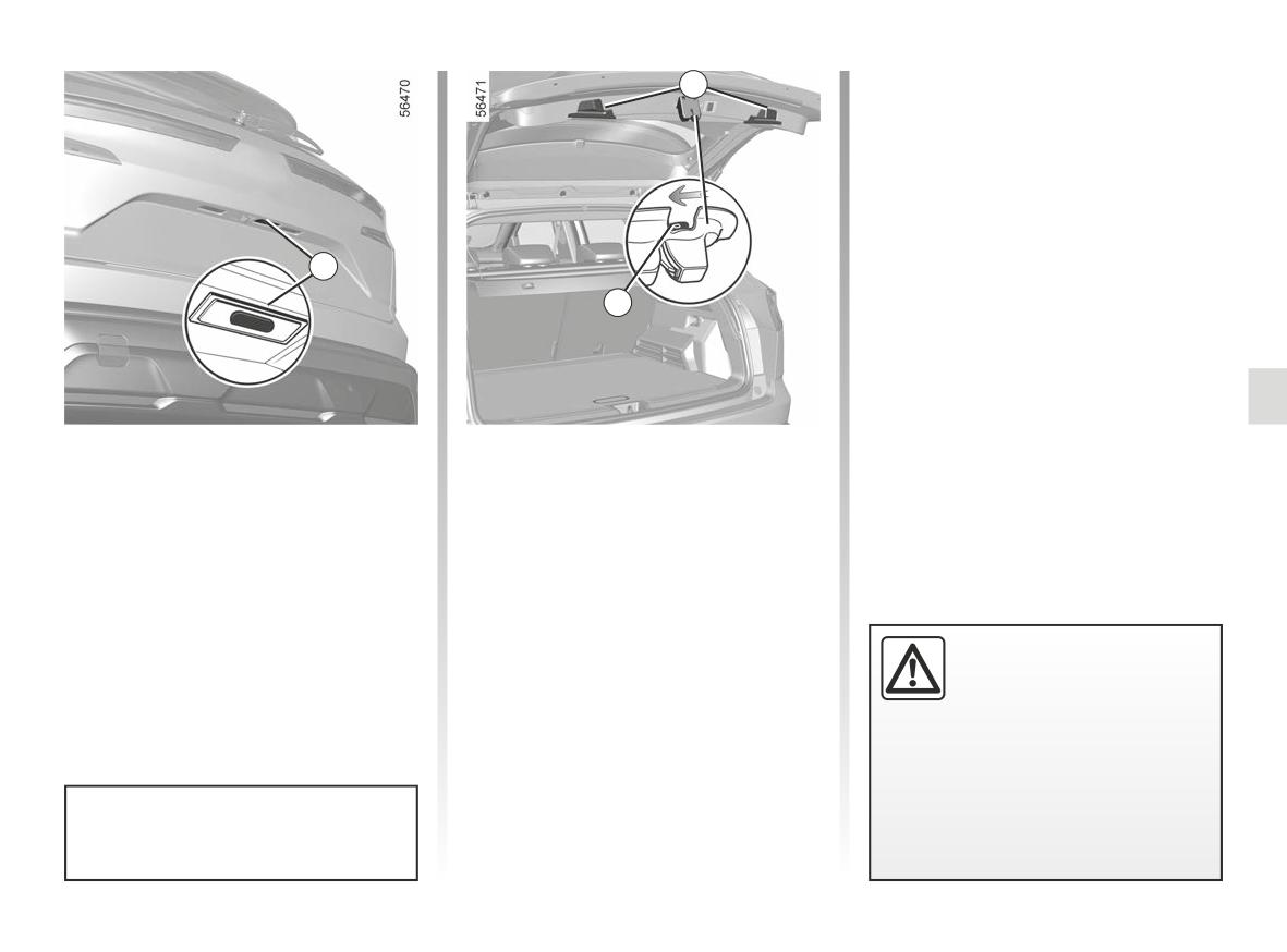
LUGGAGE COMPARTMENT, REAR PARCEL SHELF (1/2)
2
1
3
To open
Opening the doors manually
Press the 1 button and lift the door.
from the inside
If it is impossible to unlock the tailgate,
it can be done manually from inside:
To close
- access the luggage compartment by
Lower the luggage compartment door
tilting the rear bench seatback(s),
using the interior handles 2.
- insert a pencil or similar object in
recess 3 and slide the unit as shown
The attaching of any carry-
in the illustration;
ing device (bike rack, lug-
- push the tailgate to open it.
gage box etc.) resting on
the luggage compartment
lid is prohibited. To install a carrying
device on your vehicle, contact an
Approved Dealer.
Never use the struts to close the
luggage compartment door.
3.35
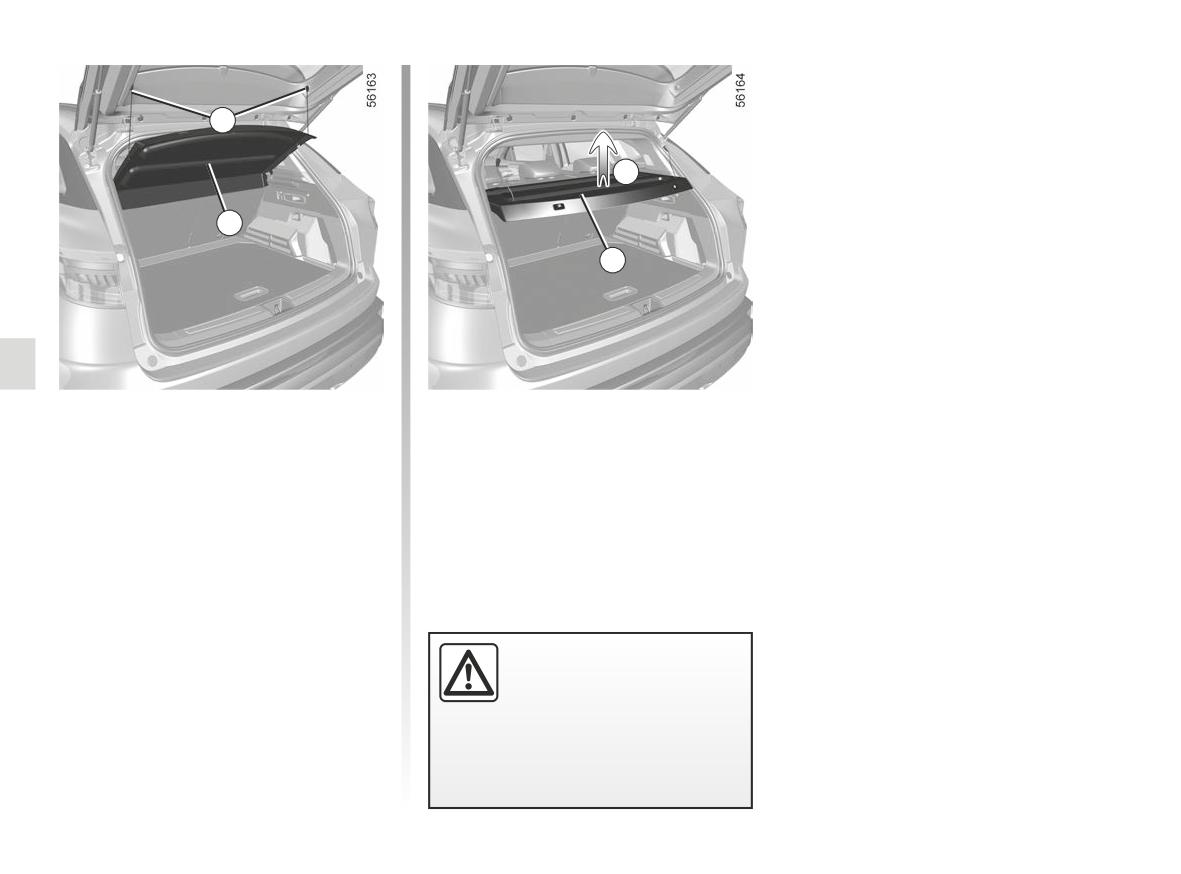
LUGGAGE COMPARTMENT, REAR PARCEL SHELF (2/2)
4
A
5
5
Rear parcel shelf, removal
- Unhook the two straps 4 of the door
of the boot;
- lift the shelf 5 to unclip it (move-
ment A);
- pull the shelf towards you.
To refit, proceed in the reverse order to
removal.
Do not place any heavy or
hard object on the parcel
shelf. These may pose a
risk to the vehicle occu-
pants if the driver has to brake sud-
denly or if the vehicle is involved in
an accident.
3.36
AUTOMATIC TAILGATE (1/6)
Conditions of use
Opening/Closing
Depending on the equipment, the tail-
gate locks and unlocks at the same
- Immobilise the vehicle.
When the motorised tailgate opening or
time as the doors.
closing function is activated using the
- If there is any ice or snow prevent-
The following modes are available to
dashboard control or using the card
ing the tailgate from opening, this ice
manoeuvre the tailgate:
(see following pages), three beeps will
or snow must be removed to free the
sound just before the tailgate begins to
- using the remote control card;
tailgate.
move.
- In the event that the battery is dis-
- using the controls on the tailgate;
charged or if it is replaced, the tail-
- using the dashboard control;
gate should be closed (manually
- depending on the vehicle, using the
if necessary) to restart the tailgate
«hands-free» function.
motor.
Ensure that nobody is close
to the moving parts when
opening/closing the tail-
To avoid damaging the tailgate
gate.
When opening or closing the tail-
system, do not manually force the
Risk of injury.
tailgate to open or close while it is
gate, ensure that nothing interferes
with the manoeuvre.
moving.
3.37
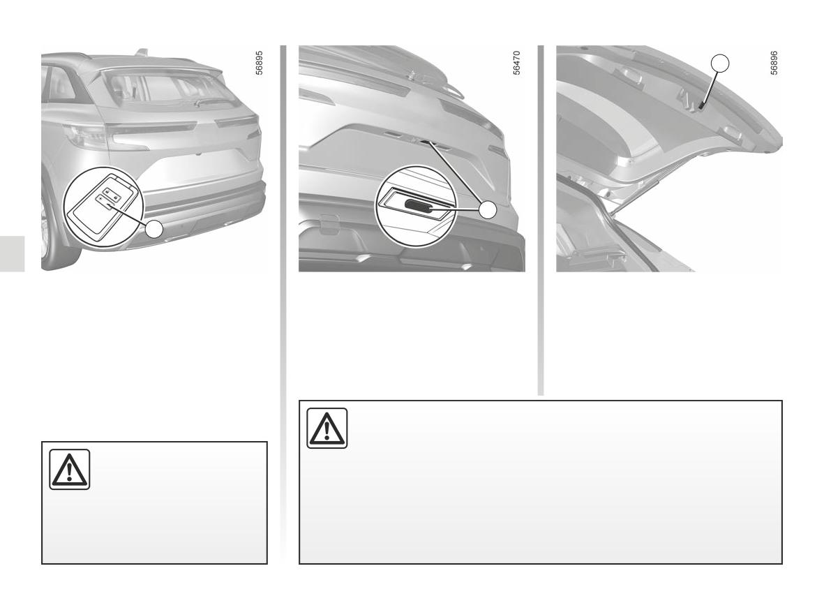
AUTOMATIC TAILGATE (2/6)
3
2
1
using the remote control card
Using the tailgate exterior opening
Using the tailgate interior closing
control
control
With the engine off, press and hold
the 1 switch on the card while near the
Press control 2.
Press control 3.
luggage compartment.
Disable the “hands-free” function before you:
- wash the vehicle in a roller-type car wash;
As a safety precaution,
- wash the vehicle by hand;
the doors should only be
- handle the emergency spare wheel or the towing equipment;
opened/closed when the
vehicle is stationary.
- ...
Risk of injury.
Risk of accidental opening of the tailgate which may cause injury.
3.38
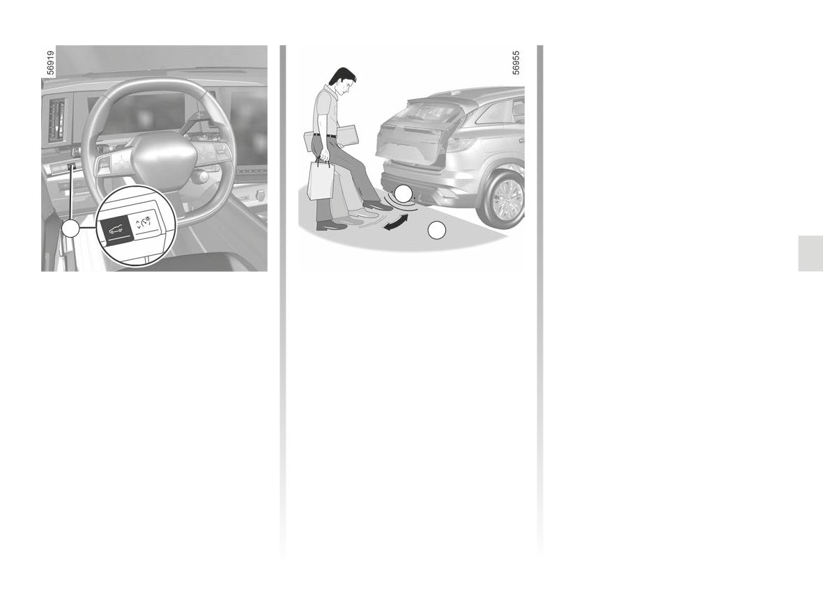
AUTOMATIC TAILGATE (3/6)
The sensor detects the approach and
removal of your foot and triggers the
opening or closing of the tailgate.
Do not keep your foot in the air. Perform
the movement without stopping and
without touching the rear bumper.
Note: with the tailgate open, after de-
tecting a closure control, it waits around
three seconds before triggering the clo-
A
sure (a beep is emitted every second).
Activation/deactivation of the
4
B
hands-free function
(depending on the multimedia system)
From the multimedia screen, in the
Using the dashboard control
Using the hands-free function
“Vehicle” mode, select the “Vehicle”
(depending on the vehicle)
tab, followed by the “Access” menu.
Press and hold switch 4.
Activate or deactivate “Hands-free lock/
The hands-free function enables
unlock”.
access to the luggage compartment
when you have your hands full. Ensure
that the card is located in the rear area
of the vehicle (area B). Stand approx-
imately 45 centimetres from the vehi-
cle’s rear bumper and move your foot
forwards and backwards in area A.
3.39
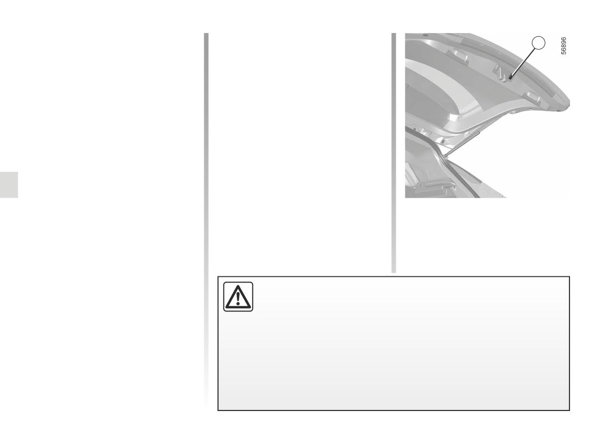
AUTOMATIC TAILGATE (4/6)
Usage features of the hands-free
Manual mode
3
function
After stopping the tailgate, you can per-
- The hands-free function is no longer
form the manoeuvre manually if you
available after a few days of lack of
wish.
movement of the vehicle, or after
around 10 minutes if the vehicle is
You can switch to the automatic ma-
unlocked. To reactivate it, use the
noeuvre at any time by pressing one of
unlocking button on the card.
the controls.
- The “hands-free” function is only
available if the vehicle is stationary
Obstacle detection
and the engine is switched off (and
not on standby with the “Stop and
If the tailgate detects an obstacle
start" function).
during its manoeuvre then it will stop. It
- The “hands-free” feature may not
will then be released from the obstacle
work if the vehicle is equipped with a
following a small movement in the op-
towbar or is in an area of high elec-
posite direction, before stopping com-
tromagnetic radiation.
pletely.
Note: detection is inactive in the last
Press a tailgate opening/closing control
centimetre before the tailgate is com-
to resume the tailgate operation.
pletely closed.
Stopping the tailgate
manoeuvre
The automatic tailgate manoeuvre can
be stopped at any time by a short press
on one of the controls.
The obstacle detection is an aid to opening and closing the tailgate, it
If the tailgate is stationary in the inter-
does not in any way replace the user’s care or responsibility.
mediate position, your next press will
When opening/closing the tailgate, small objects may not be detected.
move the tailgate in the opposite direc-
tion to when you stopped it.
Ensure that no body parts (arms, hands, fingers etc.) are near the moving tail-
gate parts.
If something gets caught, stop the manoeuvre and immediately reverse the direc-
tion of travel by pressing the control 3 twice.
Risk of serious injury.
3.40
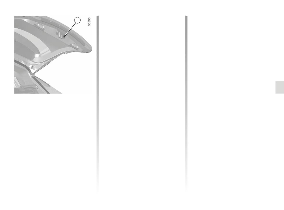
AUTOMATIC TAILGATE (5/6)
Precautions during use
Operating faults
3
- Before opening/closing the tailgate,
If you activate the automatic tailgate
ensure that the surrounding space is
continuously for around a minute (se-
sufficient to allow the tailgate to op-
quence of opening and closing), it will
erate. If not, stop the tailgate move-
stop in order to avoid overheating. The
ment.
operation will return to normal after
about a minute.
- Avoid multiple manual stops during
the automatic tailgate move-
The automatic tailgate will not operate
ment (risk of damaging the tailgate
if the battery is on low charge. In this
system).
case, operate the automatic tailgate
with the engine started.
- The “hands-free” system may be
temporarily disrupted if the rear
Note: in very cold weather conditions,
bumper is dirty (dirt, mud, snow,
the automatic opening may not work if
gritting salt, etc.). Clean the rear
the tailgate seals are frozen.
bumper. If there is still a problem,
Limiting the tailgate opening
contact an approved dealer.
angle
You can adjust the maximum tailgate
opening height It will always stop at the
chosen position:
- open the tailgate to an intermediate
position;
- manually adjust the tailgate to the
chosen position;
- press the automatic tailgate control 3
for more than three seconds to save
the position.
Two beeps will sound to notify you
that the position has been saved.
3.41
AUTOMATIC TAILGATE (6/6)
Driver’s responsibility
when parking or stopping
the vehicle
Never leave your vehicle
with a child, an adult who is not self-
sufficient or a pet inside or at the
rear of the tailgate, even for a short
while.
They may pose a risk to themselves
or to others by starting the engine,
activating equipment such as the
electric windows, the automatic
tailgate or by locking the doors.
RISK OF DEATH OR SERIOUS
The attaching of any carry-
INJURY.
ing device (bike rack, lug-
gage box, etc.) resting on
the luggage compartment
lid is prohibited. To install a carrying
device on your vehicle, contact an
Approved Dealer.
3.42
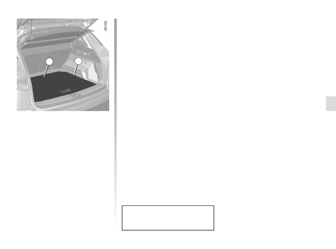
LUGGAGE COMPARTMENT STORAGE
1
2
Mobile floor 1
(depending on the vehicle)
This enables you to compartmentalise
the luggage compartment into two sep-
arate spaces.
The mobile floor is positioned on the
runner 2.
Maximum weight for the mobile
floor: 100 kg evenly distributed.
3.43
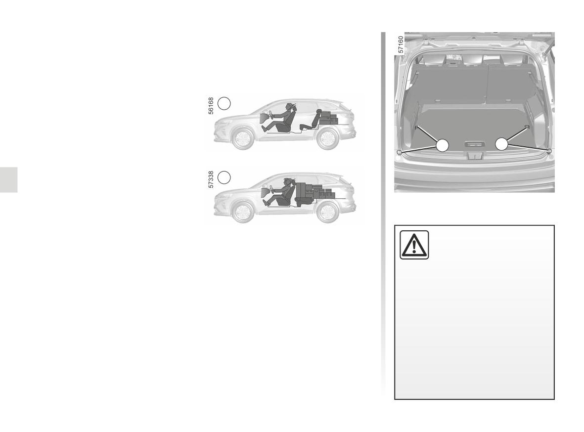
TRANSPORTING OBJECTS IN THE LUGGAGE COMPARTMENT
Always position the objects transported
so that the largest surface is against:
- the rear bench seatback, for normal
loading (example A);
A
1
1
– the front seatbacks with the rear seat-
backs folded down, as is the case for
B
maximum loads (example B).
Always position the heavi-
Ensure that the objects being trans-
est items directly on the
ported are evenly distributed throughout
floor. Use the lashing
the loading area.
points 1 on the boot floor, if
If you have to place objects on the folded
these are fitted to the vehicle. The
seatback, it is vital that you remove the
luggage should be loaded in such a
headrests before folding the seatback so
way that no items will be thrown for-
that it can be folded as flat as possible
ward and strike the occupants if the
against the seat.
driver has to brake suddenly. Fasten
the rear seat belts, even if the seats
are not occupied.
3.44
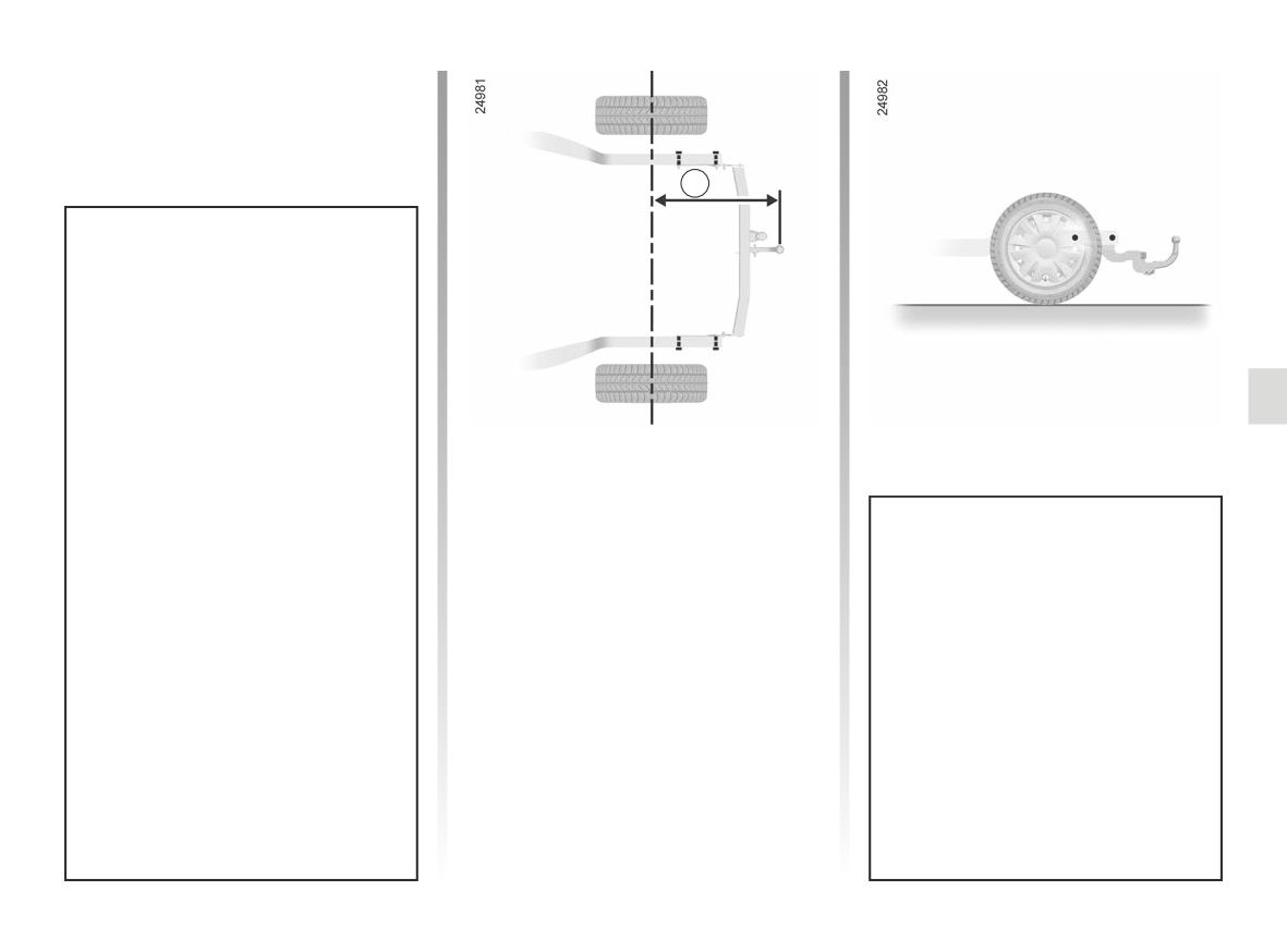
TRANSPORTING OBJECTS: towing
A
Permissible nose weight, maxi- -
mum permissible towing weight
braked and unbraked: ➥ 6.9.
Choice and fitting of towing
equipment
Maximum dimension A: 1,042 mm.
Maximum weight of towing equip-
ment: 32 kg on a vehicle not fitted
with towing pre-equipment.
It is not permitted to fit a mechanical
towing device (ball, hook, etc.) that
is removable without tools or retract-
Any towing device must not ob-
able if it cannot be easily removed
struct any lighting component or
or repositioned when not in use.
the number plate when not in use.
Mechanical towing devices (ball,
For fitting and conditions of use,
hook, etc.) which can be removed
refer to the equipment’s fitting in-
without tools or which are retract-
structions.
able must be removed or reposi-
Please keep these instructions with
tioned when they are not in use.
the rest of the vehicle documenta-
In all cases, you must comply with
tion.
the regulations of the particular
country you are in.
3.45