Peugeot 3008 (2024 year). Manual in english - page 3
Driving
(50 km/h), if both sensors are able to detect
The brake pedal may feel hard and
sensor, see User Manual" if the sensor is
6
the thread.
vibrate slightly while the function is
masked.
operating.
This is a normal behavior, which does not
If the vehicle comes to a complete stop,
request the support of a qualified workshop.
Operation
automatic braking is maintained for 1 to 2
In this case, stop the vehicle and verify if the
The system operates subject to the following
seconds.
front camera or the front radar is covered by dirt,
conditions:
mud, sand, snow, ice or anything preventing the
- At reduced speed in an urban environment,
sensing.
when a stationary vehicle, pedestrian or cyclist
Deactivation/Activation
The system is operational again after the
is detected.
By default, the system is automatically activated
detection field has been cleaned.
- The vehicle's speed is between 6 mph and
at every engine start.
In the event of a malfunction, this warning
53 mph (10 km/h and 85 km/h) (versions with
The settings are changed via the
lamp lights up on the instrument panel,
camera only) or 87 mph (140 km/h) (versions
Driving/Vehicle touch screen menu.
accompanied by the display of a message and
with camera and radar) when a moving vehicle
Deactivation of the system is signalled by
an audible signal.
is detected.
the illumination of this warning lamp,
Have it checked by a PEUGEOT dealer or a
This warning lamp flashes (for
accompanied by the display of a message.
qualified workshop.
approximately 10 seconds) as soon as
These warning lamps light up on
The system cannot be deactivated above
the function applies the vehicle’s brakes.
the instrument panel and/or in the
10 km/h.
During the flashing time, the function is not
warning lamp display for seat belts and front
available.
passenger airbag to indicate that the driver's
With an automatic gearbox, in the event of
Malfunction
and/or front passenger's seat belt is not fastened
automatic emergency braking, keep the brake
This warning lamp lights up on the
(depending on version). The automatic braking
pedal depressed, also after a complete stop is
instrument panel with the message
system is deactivated until the seat belts are
reached, to prevent the vehicle from rolling away.
"Audible Warning System fault: Repair
fastened.
With a manual gearbox, in the event of automatic
needed" if the audible warning system is in
emergency braking bringing the vehicle to a
failure.
complete stop, the engine may stall.
Distraction detection
The system may be disturbed or unavailable.
The driver can override the automatic
Have it checked by a PEUGEOT dealer or a
For more information, refer to the
emergency braking at any time by firmly
qualified workshop.
General recommendations on the use
turning the steering wheel and/or firmly
This warning lamp lights up on the
of driving and manoeuvring aids.
depressing the accelerator pedal.
instrument panel with the message
"Driving Assistance Sensor blind: Clean
Depending on version, the function consists of
either the "Driver Attention Warning" system
161
Driving
alone or combined with the "Driver Attention
As soon as the speed of the vehicle
The system may perform a learning
Warning by Camera" system.
drops below 43 mph (70 km/h), the
procedure for up to 30 minutes after the
system goes into standby.
start of the monitoring.
These systems are in no way designed
Driving time starts being counted again once
During this period, the driver's individual
to keep the driver awake or to prevent
the speed reaches above 43 mph (70 km/h).
driving behaviour is analysed and no alert is
the driver from falling asleep at the wheel.
given.
It is the driver’s responsibility to stop if feeling
tired.
Driver Attention Warning by
At a first alert level, the driver is warned by the
Take a break if you are feeling tired or at least
message "Be vigilant!", accompanied by an
Camera
every 2 hours.
audible signal.
Depending on version, the Driver Attention
After three first-level alerts, the system triggers
Warning system may be combined with the
a further alert with the message "Dangerous
Driver Attention Warning
Driver Attention Warning by Camera system.
driving: take a break", accompanied by a more
The system triggers an alert when it
pronounced audible signal.
detects that the driver has not taken a
break after two hours of driving at a speed above
In certain driving conditions (poor road
43 mph (70 km/h).
surface or strong winds), the system may
This alert is issued via the display of a message
give alerts independent of the driver's level of
encouraging the driver to take a break,
vigilance.
accompanied by an audible signal.
If the driver does not follow this advice, the alert
The following situations may interfere
is repeated hourly until the vehicle is stopped.
with the operation of the system or
The system resets itself if one of the following
prevent it from working:
conditions is met:
- Lane positioning assist is active.
- With the engine running, the vehicle has been
- poor visibility (e.g. inadequate street
The system assesses the driver's level of
stationary for more than 15 minutes.
lighting, heavy rain, thick fog, snowfall).
alertness, fatigue and distraction by
- The ignition has been switched off for a few
- dazzle (e.g. headlamps of an oncoming
identifying trajectory changes in relation to the
minutes.
vehicle, low sun, reflections on a damp road,
lane markings.
- The driver's seat belt is unfastened and their
leaving a tunnel, alternating shade and light).
To do this, the system uses a camera, placed on
door is opened.
- windscreen area located in front of the
the upper part of the windscreen.
This system is particularly suited to fast roads
camera (e.g. dirty, misted, frost-covered,
(speed higher than 43 mph (70 km/h)).
snow-covered, damaged or masked by a
sticker).
162
Driving
- lane markings absent, worn, hidden
This warning lamp lights up on the
vision) using sensors located on the sides of the
6
(e.g. snow, mud, dead leaves) or multiple
instrument panel with the message
bumpers.
(roadworks).
"Driving Assistance Sensor blind: Clean
- close to the vehicle ahead (lane markings
sensor, see User Manual" if the sensor is
not detected).
masked.
- roads that are narrow, winding.
This is a normal behavior, which does not
request the support of a qualified workshop.
In this case, stop the vehicle and verify if the
Deactivation/Activation
front camera is covered by dirt, mud, sand,
The function is activated by default when the
snow, ice or anything preventing the sensing.
A warning lamp appears in the door mirror on the
ignition is switched on.
The system is operational again after the
side in question:
The settings are changed via the
detection field has been cleaned.
- fixed, immediately, when being overtaken.
Driving/Vehicle touch screen menu.
- flashing, after a delay of about one second,
Deactivation is confirmed by the
Blind spot monitoring
when overtaking a vehicle slowly, and when the
illumination of this indicator lamp on the
direction indicator is used.
instrument panel.
For more information, refer to the
General recommendations on the use
Activation/Deactivation
Malfunction
of driving and manoeuvring aids.
It is set via the Driving/Vehicle touch
This warning lamp lights up on the
screen menu.
instrument panel with the message
When the function is activated, this
"Audible Warning System fault: Repair
indicator lamp comes on in the instrument
needed" if the audible warning system is in
panel.
failure.
When starting the vehicle, the warning lamp
The system may be disturbed or unavailable.
comes on in each mirror to indicate that the
Have it checked by a PEUGEOT dealer or a
system is activated.
qualified workshop.
The status of the system is memorised when the
In the event of a malfunction, this warning
ignition is switched off.
lamp lights up on the instrument panel,
accompanied by the display of a message and
The system is automatically deactivated
This system warns the driver of a potential
an audible signal.
when towing with a towing device
danger posed by the presence of another vehicle
Have it checked by a PEUGEOT dealer or a
approved by PEUGEOT.
(car, lorry, motorcycle) in the vehicle's blind
qualified workshop.
spots (areas hidden from the driver's field of
163
Driving
Operating conditions
Operating limits
- presence of stationary objects (e.g. parked
vehicles, safety rails, lampposts, signs).
- All vehicles are moving in the same direction
- vehicles travelling in the opposite direction.
and in adjacent lanes.
- on winding roads or in case of sharp turns.
- The speed of your vehicle must be between 7
- when overtaking or being overtaken by a
and 87 mph (12 and 140 km/h).
very long vehicle (e.g. truck, bus), which is both
- When overtaking a vehicle, the speed
detected in a blind spot from behind and present
difference is less than 6 mph (10 km/h).
in the driver's field of vision from the front.
- When overtaken by a vehicle, the speed
- quick overtaking manoeuvre.
difference is less than 16 mph (25 km/h).
- very heavy traffic: vehicles detected in front
- Traffic is flowing normally.
and behind are confused with a lorry or a
- Overtaking a vehicle over a certain period of
stationary object.
time and the vehicle being overtaken remains in
- activation of the Park Assist function.
the blind spot.
- You are driving on a straight or slightly curved
Malfunction
road.
In the event of a malfunction, this
- Your vehicle is not pulling a trailer, a caravan,
warning lamp flashes for a few
etc.
moments in the instrument panel, accompanied
by the Service warning lamp coming on and the
display of a message.
Have it checked by a PEUGEOT dealer or a
qualified workshop.
The system may be temporarily disturbed
by certain climatic conditions (e.g. rain,
hail).
In particular, driving on a wet road or going
from a dry to a wet area can cause false
alerts (e.g. presence of a cloud of water
droplets in the blind spot interpreted as a
vehicle).
In bad or wintry weather, ensure that the
No alert is triggered in the following conditions:
sensors are not covered by mud, ice or snow.
164
Driving
Take care not to cover the warning zone in
If an obstacle is detected as soon as the
The audible signal is automatically restored
6
the door mirrors, or the detection zones on
reverse gear is engaged, an audible
when the vehicle is moving again or if the
the front and rear bumpers with adhesive
detection signal is given directly instead of the
obstacle approaches the vehicle.
labels or other objects; they may hamper
audible confirmation signal.
Adjusting the audible signal
correct operation of the system.
If no audible signal is given, the display
Depending on version, with
indication is not shown or a warning message
PEUGEOT Connect Radio or
appears, the system has a failure.
PEUGEOT Connect Nav, pressing this button
Parking sensors
opens the window for adjusting the volume of
Audible assistance
the audible signal.
For more information, refer to the
General recommendations on the use
of driving and manoeuvring aids.
Visual assistance
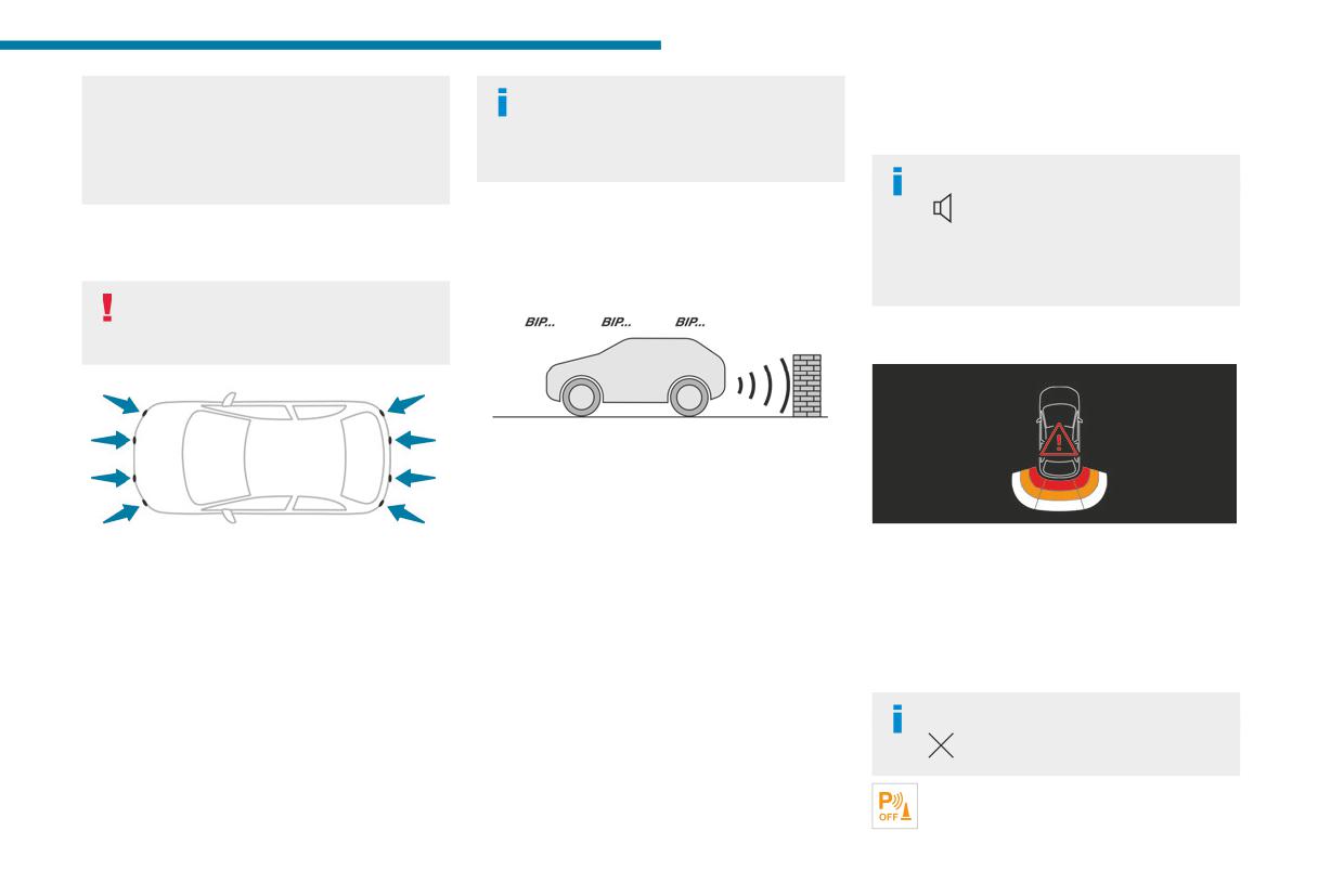
The system signals the presence of obstacles
within the sensors’ detection zone.
The proximity information is given by an
intermittent audible signal, the frequency of
which increases as the vehicle approaches the
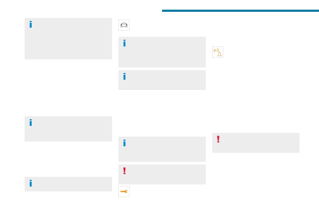
This supplements the audible signal by
This system detects and signals the proximity of
obstacle.
displaying bars on the screen whose location
obstacles (e.g. pedestrian, vehicle, tree, barrier)
When the distance between the vehicle and
represents the distance between the obstacle
using sensors located in the bumper.
the obstacle becomes less than about thirty
and the vehicle (white: more distant, orange:
centimetres, the audible signal becomes
close, red: very close).
Rear parking sensors
continuous.
When the obstacle is very close, the "Danger"
System startup is available under the following
The sound emitted by the speaker (right or
symbol is displayed on the screen.
conditions:
left) indicates the side on which the obstacle is
- when reverse gear is engaged.
located.
Closing the system display window
- when the vehicle is moving backwards
The audible signal is automatically suspended
Pressing this button closes the
(e.g. downhill, in neutral).
when the vehicle is stationary for a few seconds.
system display window.
It is indicated by an audible confirmation signal
This warning lamp flashes during obstacle
and a display indication.
detection on the instrument panel.
165
Driving
Muting the audible assistance /
You can start the system manually and
lamp lights up on the instrument panel,
Closing the visual assistance
activate/deactivate the audible signal in
accompanied by the display of a message and
If the audible detection signal is muted or the
the Driving/Vehicle touch screen menu.
an audible signal (short beep).
system display window is closed manually by
Have it checked by a PEUGEOT dealer or a
The rear parking sensors system will be
the driver with the button above during the
qualified workshop.
deactivated automatically if a trailer or
obstacle detection, only the warning lamp
This warning lamp lights up on the
bicycle carrier is connected to a towing device
continues to flash on the instrument panel.
instrument panel with the message
installed in accordance with the
"Parking Assistance Sensor blind: Clean
manufacturer's recommendations.
sensor, see User Manual" if the sensor is
Front parking sensors
masked.
Supplementing the rear parking sensors, the
When starting the vehicle, the graphic
This is a normal behavior, which does not
front parking sensors are triggered when an
and audible aids are only available after
request the support of a qualified workshop.
obstacle is detected in front and the speed of the
the touch screen has started up.
In this case, stop the vehicle and verify if the
vehicle is below 6 mph (10 km/h).
front and/or rear sensors are covered by dirt,
Front parking sensor operation is suspended if
mud, sand, snow, ice or anything preventing the
Operating limits
the vehicle stops for more than three seconds in
sensing.
If the boot is heavily loaded, the vehicle may tilt,
forward gear, if an obstacle is no longer detected
The system is operational again after the
affecting distance measurements.
or the vehicle speed exceeds 6 mph (10 km/h).
detection field has been cleaned.
In case of a gearbox failure, the system is not
The sound emitted by the speaker (front
active, when the reverse gear is engaged.
or rear) locates the obstacle relative to
Visiopark 1 - Visiopark 2
the vehicle, whether in front of or behind it on
Malfunction
its path.
For more information, refer to the
In case of display or speakers
General recommendations on the use
malfunction (e.g. frozen image, black
of driving and manoeuvring aids.
Deactivation/Activation
screen), the system may be disturbed or
(Depending on country of sale)
unavailable.
By default, the audible signal is automatically
activated at each time the reverse gear is
In the event of vehicle malfunction that
engaged.
requires the vehicle to be stopped, the
system may be deactivated.
The system cannot be deactivated.
In the event of a malfunction when
changing into reverse gear, this warning
166
Driving
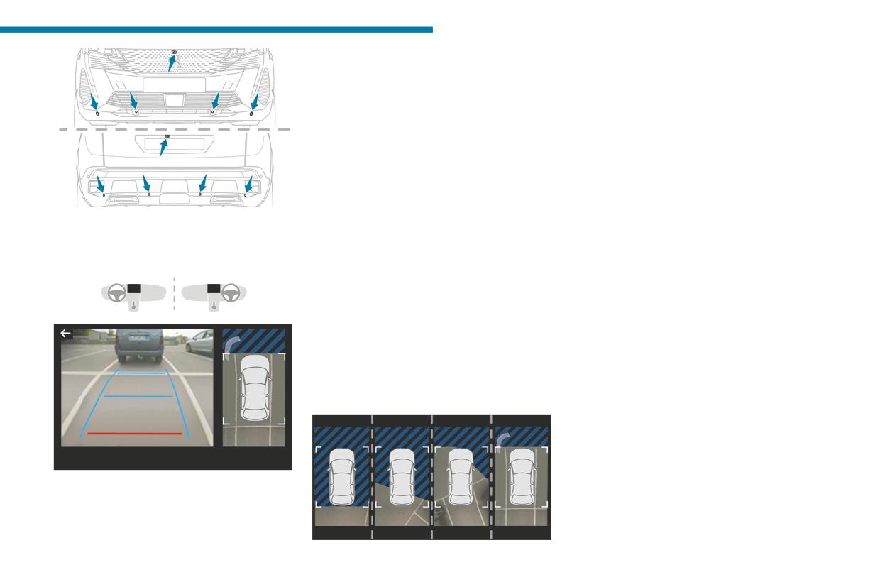
The parking sensors supplement the information
Using one or two cameras, the close
6
on the view from above the vehicle.
surroundings of the vehicle are recorded whilst
Various contextual views may be displayed:
manoeuvring at low speed.
- Standard view.
An image from above your vehicle in its close
- 180° view.
surroundings is reconstructed (represented
- Zoom view.
between the brackets) in real time and as the
AUTO mode is activated by default.
manoeuvre progresses.
In this mode, the system chooses the best
It facilitates the alignment of your vehicle when
view to display (standard or zoom).
parking and allows obstacles close to the vehicle
You can change the type of view at any time
to be seen. It is automatically deleted if the
during a manoeuvre.
vehicle remains stationary for too long.
With the engine running, these systems allow
► Press the button in the bottom left-hand
With Visiopark 2, the image is created using
views of your vehicle’s close surroundings to be
corner of the touch screen.
both cameras, when going forward and when
displayed on the touch screen using one camera
► Select the type of view:
reversing.
for Visiopark 1 and two cameras for Visiopark 2.
• "Standard view".
When the function is activated, it is possible
• "180° view".
that the view from above is not displayed. If
• "Zoom view".
the system is activated when the vehicle has
• "AUTO view".
already moved, the view from above can be fully
The display is immediately updated with the type
displayed.
of view selected.
The system status is not saved when the ignition
is switched off.
Operating principle
The screen is divided into two parts with a
contextual view and a view from above the
vehicle in its close surroundings.
167
Driving
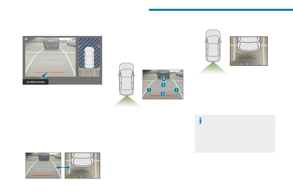
Visiopark 1
This mode is activated by default.
Zoom view
Using sensors in the rear bumper, the automatic
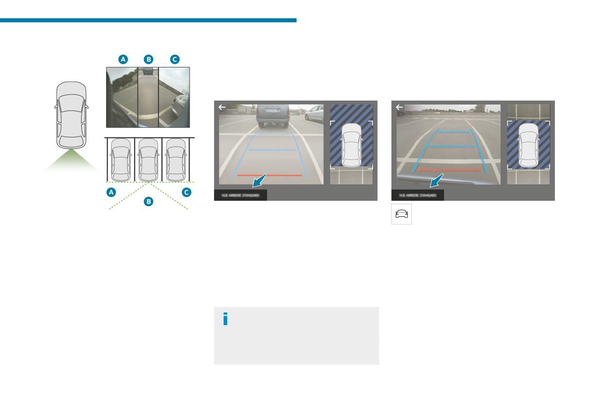
Rear view
view changes from the rear view (standard) to
the view from above (zoom) as an obstacle is
approached at the level of the red line (less than
30 cm) during a manoeuvre.
Standard view
The camera records the vehicle's surroundings
during the manoeuvre in order to create a
To activate the camera located on the tailgate,
view from above the rear of the vehicle in its
engage reverse gear and do not exceed a speed
near surroundings, allowing the vehicle to be
of 6 mph (10 km/h).
manoeuvred around nearby obstacles.
The system is deactivated:
This view is available with AUTO mode or in the
- Automatically, at speeds above approximately
view selection menu.
6 mph (10 km/h),
The area behind the vehicle is displayed on the
- Automatically, if the tailgate is opened.
Obstacles may appear further away than
screen.
- Upon changing out of reverse gear (the image
they actually are.
The blue lines 1 represent the width of your
remains displayed for 7 seconds).
It is important to monitor the sides of the
vehicle, with the mirrors unfolded; their direction
- By pressing the white arrow in the upper-left
vehicle during the manoeuvre, using the
changes according to the position of the steering
corner of the touch screen.
mirrors.
wheel.
Parking sensors also provide additional
The red line 2 represents a distance of 30 cm
AUTO mode
information about the area around the vehicle.
from the rear bumper; the two blue lines 3 and 4
represent 1 m and 2 m, respectively.
This view is available with AUTO mode or in the
view selection menu.
168
Driving
180° view
offering views from the rear of the vehicle (rear
The rear vision views are similar to those for the
6
vision) when reverse gear is engaged and views
Visiopark 1 function.
from the front of the vehicle (front vision) when
For more information on the Visiopark
the gearbox is in neutral or a gear is engaged.
1 function, refer to the corresponding section.
Rear vision
Front and rear vision
The system activates automatically when
With the engine running and the speed
The 180° view facilitates reversing out of a
reverse gear is engaged.
below 12 mph (20 km/h), the system is
parking space, making it possible to see the
The system is deactivated:
activated via the Driving/Vehicle touch screen
approach of vehicles, pedestrians and cyclists.
- Automatically, at speeds above approximately
menu:
This view is not recommended for carrying out a
12 mph (20 km/h).
► Select "Visual parking assistance".
complete manoeuvre.
- When shifting out of reverse (the front vision
AUTO mode is displayed by default, with front
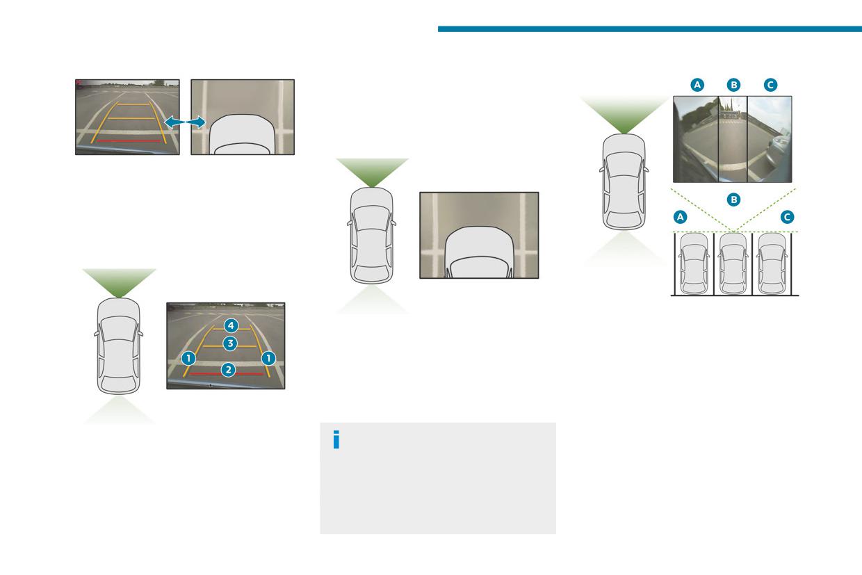
It features 3 areas: left A, centre B and right C.
image replaces the rear vision image for 7
vision, if the gearbox is in neutral or with a
This view is only available via the view selection
seconds).
gear engaged, or with rear vision, if reverse is
menu.
- By pressing the white arrow in the upper-left
engaged.
corner of the touch screen.
The system is deactivated:
Visiopark 2
- Automatically above about 19 mph (30 km/h)
If a trailer or a bicycle carrier is fitted to
The vehicle has a camera at the front, fitted in
(the image disappears temporarily from 12 mph
the towball, the area behind the vehicle
the grille, and a camera at the rear, located close
(20 km/h)).
on the view from above goes dark.
to the tailgate opening control.
- By pressing the white arrow in the upper-left
The surroundings are reconstructed by the
Using these cameras, the system displays the
corner of the touch screen.
front camera only.
vehicle's near surroundings on the touch screen,
169
Driving
AUTO mode
The red line 2 represents a distance of 30 cm
180° view
from the front bumper; the two orange lines 3
and 4 represent 1 m and 2 m, respectively.
This view is available with AUTO mode or by
selecting it in the view change menu.
Zoom view
This mode is activated by default.
Using sensors in the front bumper, the automatic
view changes from the front view (standard) to
the view from above (zoom) as an obstacle is
approached during a manoeuvre.
Standard view
The 180° view assists with exiting from a parking
The camera records the vehicle's surroundings
space in forward gear, making it possible to
during the manoeuvre in order to create a
see the approach of vehicles, pedestrians and
view from above the front of the vehicle in its
cyclists.
near surroundings, allowing the vehicle to be
This view is not recommended for carrying out a
manoeuvred around obstacles nearby.
complete manoeuvre.
This view is available with AUTO mode or in the
It consists of 3 areas: left A, centre B and right
view selection menu.
C.
This view is available only from the view
The area in front of your vehicle is displayed on
Obstacles may appear further away than
selection menu.
the screen.
they actually are.
The orange lines 1 represent the width of your
It is important to check the sides of the
vehicle, with the mirrors unfolded; their direction
vehicle during the manoeuvre, using the
changes according to the position of the steering
mirrors.
wheel.
The parking sensors also supplement the
information on the vehicle's surroundings.
170
Driving
The Parking sensors function is not
Park Assist
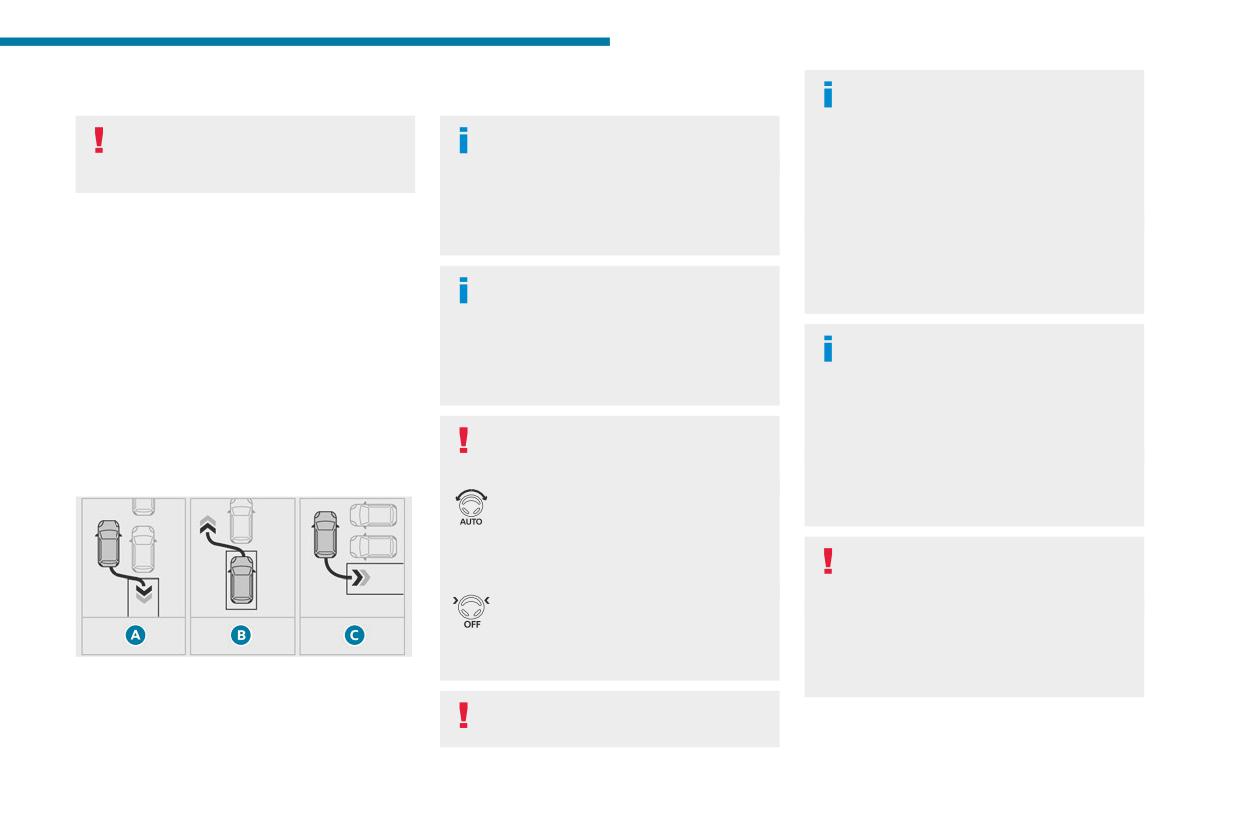
C. Entry into a "bay" parking space
6
available during parking space
For more information, refer to the
The Park Assist system cannot operate
measurement. It intervenes later when
General recommendations on the use
with the engine switched off.
manoeuvring to warn that the vehicle is
of driving and manoeuvring aids.
When Park Assist is activated, it prevents
approaching an obstacle: the audible signal
Stop & Start from going into STOP mode. In
becomes continuous when the obstacle is
This system provides active parking assistance:
less than 30 centimetres away.
STOP mode, activation of Park Assist restarts
it detects a parking space then operates the
If the Parking sensors function has
the engine.
steering system to park in this space.
been deactivated, it will be automatically
With a manual gearbox, the driver manages the
reactivated during the assisted manoeuvring
The Park Assist system takes control of
accelerator, brakes, gears and clutch.
phases.
the steering for a maximum of 4
With an automatic gearbox, the driver manages
manoeuvring cycles. It is deactivated after
the accelerator, brakes and gears.
these 4 cycles. If the vehicle is not positioned
During parking and exit from parking
During phases of entry into and exit from a
correctly, take back control to complete the
manoeuvres, the Visiopark 1 - Visiopark
parking space, the system provides visual and
manoeuvre.
2 functions may come into operation. They
audible information to the driver in order to make
allow better monitoring of the surroundings of
the manoeuvres safe. Several forward and
the vehicle, by displaying additional
The sequence of manoeuvres and the
reverse manoeuvres may be required.
information in the touch screen.
driving instructions are displayed in the
At any time, the driver can take back control by
For more information on the Visiopark
instrument panel.
holding the steering wheel.
1 - Visiopark 2 functions, refer to the
The assistance is activated: the display
corresponding section.
of this symbol and a speed limit
indicate that the steering manoeuvres are
controlled by the system: do not touch the
In some circumstances, the sensors may
steering wheel.
not detect small obstacles located in their
The assistance is deactivated: the
blind spots.
display of this symbol indicates that the
Any object exceeding the size of the vehicle
steering manoeuvres are no longer controlled
(e.g. roof ladder, towball) is not taken
by the system: take over the steering.
into account by the Park Assist during a
The Park Assist system provides assistance for
manoeuvre.
the following manoeuvres:
Activation of Park Assist deactivates the
A. Entry into a "parallel" parking space
Blind spot monitoring.
B. Exit from a "parallel" parking space
171
Driving
Always check the surroundings of the
► Drive at a speed below 12 mph (20
at a distance of between 0.5 m and 1.5 m from
20
vehicle before starting a manoeuvre.
km/h) following the instructions until the
the row of parked vehicles.
If the lateral distance between the vehicle and
system finds an available space.
► Drive at a speed below 12 mph (20
20
the space is too great, the system may not be
► Move forwards slowly until a message
km/h) following the instructions until the
able to measure the space.
is displayed, accompanied by an audible
system finds an available space.
signal, asking you to engage reverse gear.
When several successive spaces are
During manoeuvring phases, the steering
► Engage reverse gear, release the
found, the vehicle will be directed
wheel performs rapid turns: do not hold
steering wheel and move without
towards the last one.
the steering wheel or put your hands between
exceeding a speed of 4 mph (7 km/h).
the spokes of the steering wheel.
The assisted parking manoeuvre is in
► Move forwards slowly until a message
Beware of any object likely to block the
progress.
is displayed, accompanied by an audible
manoeuvre (e.g. loose clothing, scarves, ties)
► Without exceeding 5 mph (7 km/h),
signal, asking you to engage reverse gear.
7
- risk of injury!
move forwards and backwards, aided by
► Engage reverse gear, release the
the warnings from the "Parking sensors" system,
steering wheel and move without
until the end of the manoeuvre is indicated.
exceeding the speed of 5 mph (7 km/h).
Assistance with "parallel"
The end of the manoeuvre is confirmed
The assisted parking manoeuvre is in
parking manoeuvres
by a message and an audible signal.
progress.
Parking assistance is deactivated: you can take
► Without exceeding 5 mph (7 km/h),
► When parking, select "Park Assist" in
over the controls again.
7
the Driving/Vehicle touch screen menu
follow the instructions and the warnings
to activate the function.
from the "Parking sensors" system, until the end
Assistance with "bay"
► Limit the vehicle speed to a maximum
of the manoeuvre is indicated.
of 12 mph (20 km/h) and select "Enter
parking manoeuvres
The end of the manoeuvre is confirmed
parallel parking space" on the touch screen.
► When parking, select “Park Assist” in
by a message and an audible signal.
The system is deactivated: it is possible to retake
the Driving/Vehicle touch screen menu
To enter a "parallel" parking space, the
control.
to activate the function.
system does not identify spaces that are
► Limit the vehicle speed to a maximum
During a "bay" parking manoeuvre, the
clearly smaller or larger than the vehicle.
of 12 mph (20 km/h) and select “Enter
Park Assist system is automatically
► Operate the direction indicator on the
bay parking space” on the touch screen.
deactivated once the rear of the vehicle is
side you have chosen to park in order to
► Operate the direction indicator on the
within 50 cm of an obstacle.
activate the measurement function. The vehicle
parking side chosen to activate the
must drive at a distance of between 0.5 m and
measurement function. The vehicle should drive
1.5 m from the row of parked vehicles.
172
Driving
Assistance with "parallel"
- if the engine stalls.
In the event of a malfunction, have the system
6
- if the driver's seat belt is not fastened.
checked by a PEUGEOT dealer or a qualified
parking exit manoeuvres
- on opening the driver's door.
workshop.
► To leave a "parallel" parking space, switch
- if no manoeuvre is performed within 5 minutes
In the event of a power steering
the engine on.
of selecting the type of manoeuvre.
malfunction, this warning lamp is
► With the vehicle stationary, select
- after a prolonged stop of the vehicle during a
displayed on the instrument panel, accompanied
"Park Assist" in the Driving/Vehicle
manoeuvre.
by a warning message.
touch screen menu to activate the function.
- if the wheel anti-slip regulation (ASR) is
You must stop as soon as it is safe to do so.
► Press "Exit parking slot" on the touch
triggered.
Contact a PEUGEOT dealer or a qualified
screen.
- if the speed of the vehicle is above 43 mph
workshop.
► Operate the direction indicator for the
(70 km/h).
exit side chosen.
- when the driver interrupts the rotation of the
► Engage reverse or forward
steering wheel.
gear and release the steering
- after 4 manoeuvring cycles.
wheel.
- if one of the front wheels encounters an
The assisted parking manoeuvre is in
obstacle.
progress.
- when towing a trailer, connected electrically.
► Without exceeding 3 mph (5 km/h),
Deactivation is confirmed by a message and an
5
move forwards and backwards, aided by
audible signal.
the warnings from the "Parking sensors" system,
The driver should then take back control of the
until the end of the manoeuvre is indicated.
vehicle's steering.
The manoeuvre is complete when the vehicle's
If the system is deactivated during a
front wheels are clear of the parking space.
manoeuvre, the driver should reactivate
The end of the manoeuvre is confirmed
it to repeat the measurement.
by a message and an audible signal.
The system is deactivated: it is possible to retake
To switch the system off for a prolonged period,
control.
contact a PEUGEOT dealer or a qualified
workshop.
Deactivation
The system is deactivated via the Driving /
Malfunctions
Vehicle touch screen menu.
If the parking sensor malfunction occurs
The system is automatically deactivated:
during use, indicated by this warning lamp
– when the ignition is switched off.
coming on, it causes the function to deactivate.
173
PEUGEOT & TotalEnergies,
a partnership in performance !
For more than 25 years of partnership, TotalEnergies and PEUGEOT
have pushed the limits of performance in sports competition with historic
victories, in endurance racing. Today, the two brands continue their
common motorsport adventure by setting out to conquer the 24h of
Le Mans and the FIA World Endurance Championship in the Hypercar
category. PEUGEOT recommends high-tech Quartz lubricants exclusively
for the protection of its engines throughout their life. TotalEnergies
therefore equips PEUGEOT vehicles with Quartz lubricants from their first
filling in the factory to the approved maintenance networks to guarantee
them optimal day-to-day operation. PEUGEOT & TotalEnergies: official
partners in performance !
Keep your engine younger for longer !
Quartz Ineo Xtra First 0W-20 is a very high performance lubricant
resulting from the common work of the PEUGEOT and TotalEnergies R&D
teams. Its innovative technology extends your engine’s life while reaching
significant fuel savings and thus limiting CO2 emissions. The product is
now available in new packaging* made of 50% recycled material and
100% recyclable.
* 1L & 5L produced in Europe
Practical information
fuels could prevent the engine from operating
panel, accompanied by the display of a message
Compatibility of fuels
7
correctly. In these temperature conditions, use
and an audible signal. When it first comes on,
winter-type Diesel fuel and keep the fuel tank
about 6 litres of fuel remain.
more than 50 % full.
Until sufficient fuel is added, this warning lamp
Petrol fuels conforming to the EN228 standard
At temperatures below -15 °C (+5 °F) to avoid
appears every time the ignition is switched on,
containing up to 5% and 10% ethanol
problems starting, it is best to park the vehicle
accompanied by the message and the audible
respectively.
under shelter (heated garage).
signal. When driving, this message and audible
signal are repeated with increasing frequency as
Travelling abroad
the fuel level drops towards 0.
Diesel fuels conforming to the EN590, EN16734
Certain fuels could damage your vehicle’s
You must refuel as soon as possible to avoid
and EN16709 standards and containing up to
engine.
running out of fuel.
7%, 10%, 20% and 30% fatty acid methyl ester
In certain countries, the use of a particular
For more information on Running out of fuel
respectively. The use of B20 or B30 fuels, even
fuel may be required (specific octane rating,
(Diesel), refer to the corresponding section.
occasionally, imposes special maintenance
specific trade name, etc.) to ensure correct
A small arrow by the warning lamp
conditions referred to as "Arduous conditions".
operation of the engine.
indicates which side of the vehicle the
For all additional information, consult a dealer.
fuel filler flap is located on.
Paraffinic Diesel fuel conforming to the EN15940
Refuelling
Stop & Start / e-Auto mode
standard.
Never refuel with the engine in STOP
The use of any other type of (bio) fuel
mode or in stand-by; you must switch off the
Fuel tank capacity:
ignition.
(e.g. pure or diluted vegetable or animal
approximately 53 litres (Petrol,
oils, domestic fuel) is strictly prohibited - risk
Diesel or Hybrid) or 43 litres
of damaging the engine and fuel system!
(Rechargeable hybrid).
Refuelling
Any addition of fuel must be in quantities of at
The only fuel additives authorised for use
Fuel tank capacity:
least 10 litres, in order to be registered by the
are those that meet the B715001 (Petrol)
approximately 56 litres.
fuel gauge.
or B715000 (Diesel) standards.
Opening the filler flap may create a noise caused
Reserve level: approximately 6 litres.
by an inrush of air. This vacuum is entirely
Diesel at low temperature
Low fuel level
normal, resulting from the sealing of the fuel
system.
At temperatures below 0 °C (+32 °F), the
When the low fuel level is reached, this
formation of paraffins in summer-type Diesel
warning lamp lights up on the instrument
175
Practical information
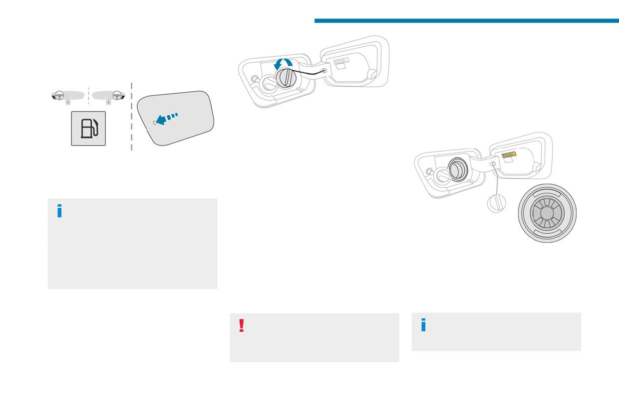
The filler cap is built into the filler flap or must be
Misfuel prevention (Diesel)
unscrewed (depending on version).
(Depending on country of sale.)
To refuel in complete safety:
This mechanical device prevents filling the tank
► Always switch off the engine.
of a Diesel vehicle with petrol.
Located in the filler neck, the misfuel prevention
device is visible when the filler cap is removed.
► Turn the filler cap to the left, remove it
Operation
and place it on its support on the filler flap
(depending on version).
► Insert the filler nozzle and push it in as far as
► To open the filler flap, press the flap opening
possible before starting to refuel (to minimise the
button for more than 2 seconds or, with the
risk of splashing).
vehicle unlocked, press the rear of the filler flap
► Fill the tank.
(depending on version).
Do not continue after the nozzle’s third cut-
out. Doing so may cause malfunctions.
Rechargeable hybrid vehicles
► Put the filler cap back in place and turn it to
After pressing the button on the
the right (depending on version).
dashboard, the filler flap may not open for
► Push the fuel filler flap to close it.
several minutes. A sound is emitted when the
The vehicle is fitted with a catalytic converter,
filler flap opens.
which helps to reduce the level of harmful
When a petrol filler nozzle is introduced into the
If the flap becomes stuck, press and hold
emissions in the exhaust gases.
fuel filler neck of a Diesel vehicle, it comes into
the button on the dashboard for more than
For petrol engines, you must use unleaded
contact with the flap. The system remains closed
3 seconds.
fuel.
and prevents filling.
► Select a pump that delivers the correct fuel
The filler neck is narrower, allowing only
Do not persist but introduce a Diesel type
type for the vehicle's engine (see a reminder
unleaded petrol nozzles to be inserted.
filler nozzle.
label on the inside of the filler flap).
If you have put in the wrong fuel for
The misfuel prevention device does not
the vehicle, you must have the fuel
prevent filling with a jerrycan, regardless
tank drained and filled with the correct fuel
of the fuel type.
before starting the engine.
176
Practical information
Travelling abroad
High voltage system voltage is
- Always inform the fire and emergency
7
As Diesel fuel pump nozzles may be
dangerous and can cause burns or other
services in the event of an incident, warning
different in other countries, the presence
injuries or even fatal electric shock.
that the vehicle is equipped with a traction
of the misfuel prevention device may make
Since damage to high voltage components is
battery.
refuelling impossible.
not visible, PEUGEOT recommends that you:
- Never touch the liquids leaking from the
Before travelling abroad, it is advisable to
- Never touch the components, damaged
traction battery.
check with a PEUGEOT dealer if the vehicle
or not, and never let your jewelry or other
- Do not inhale the gases emitted by the
is suitable for the distribution equipment of the
metallic objects come into contact with these
traction battery which are toxic.
countries visited.
components.
- Move away from the vehicle in the event of
- Never work on the purple high voltage
incident or accident, the gases emitted being
cables or on any other high voltage
flammable and could cause a fire.
Hybrid system
component marked with the Electric risk label.
Any intervention on the high voltage system
In the event of an accident with an
must be carried out by qualified persons in
airbag deployment
Electrical system
workshops qualified and approved to carry
The traction battery is automatically
The electrical circuit of the hybrid system is
out this type of work.
disconnected from the electrical circuit to
identified by purple cables and its components
- Never damage, modify or remove the
prevent the initiation of short circuits and/or
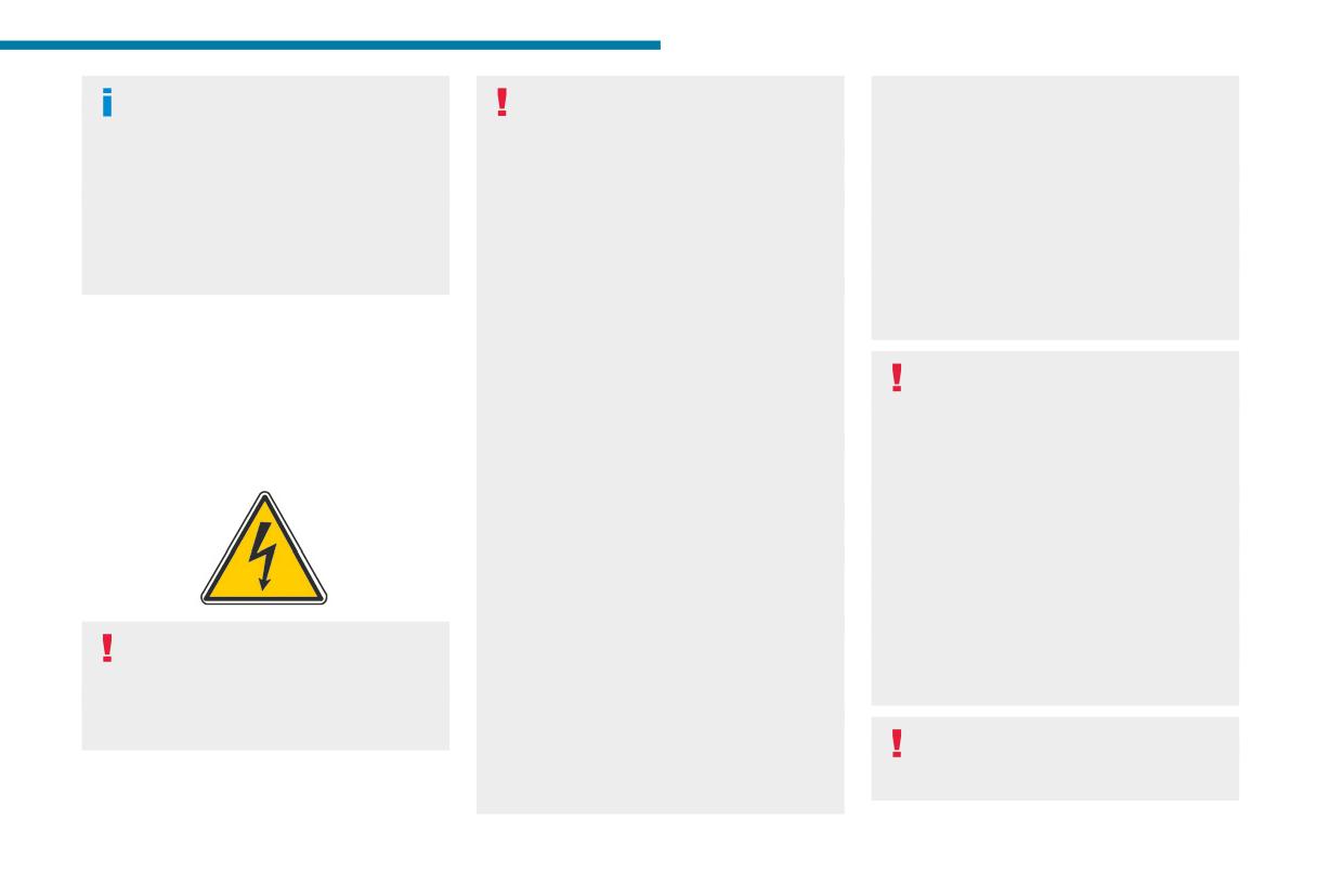
are marked with this symbol:
purple high voltage cables or disconnect them
fires.
from the high voltage network.
In the event of an impact to the vehicle’s
- Never open, modify or remove the cover of
underbody
the traction battery.
In these situations, the electrical circuit or the
- Never work with cutting and forming
traction battery can be seriously damaged.
tools or heat sources near high voltage
Stop as soon as it is safe to do so and switch
components and cables.
off the ignition.
The hybrid powertrain uses a voltage of
Any intervention on the high voltage system
Move away from the vehicle.
48 V. This system may be hot both when
must be carried out by qualified persons in
Contact a PEUGEOT dealer or a qualified
the ignition is on and after switching it off.
workshops qualified and approved to carry
workshop.
Comply with the warning messages shown on
out this type of work.
the labels.
Damage to the vehicle or the traction battery
High-pressure washing
could result in the leakage of toxic gases or
To avoid damaging the electrical
fluids either immediately or later. PEUGEOT
components, it is expressly prohibited to
recommends that you:
177
Practical information
use high-pressure washing in the engine
In the event of damage to the traction
Vehicle in storage for more than
compartment or under the body.
battery
1 month
Do not use a pressure greater than 80 bar
It is strictly prohibited to work on the vehicle
Always park the vehicle in a place with
when washing the bodywork.
yourself.
temperatures between -10°C and +30°C
Do not touch liquids coming from the battery,
(parking in a place with extreme temperatures
and in the event of skin contact with these
can damage the traction battery).
Traction battery
products, wash abundantly with water and
Carry out the charging procedure for the
The 48 V Li-ion (Lithium-ion) traction battery
contact a doctor as soon as possible.
traction battery (48V) via the accessory
stores the electrical energy needed to propel the
Contact a PEUGEOT dealer or a qualified
battery (12V) and the DC/DC converter.
vehicle.
workshop to have the system checked.
Refer to the 12 V battery/Accessory
The traction battery is automatically charged to
batteries section for the charging the
ensure that the charge level is always around
batteries using a battery charger procedure.
Traction battery overheating
50% of the maximum level, in order to fully
exploit the hybrid functionality and, at the same
If the following warning lamps
time, always have some capacity available for
appear, accompanied by the
Disposal of the traction battery
the energy recovery operation.
display of a message and an audible signal, it is
The traction battery is designed for the life of the
It is located under the front left seat.
required to:
vehicle if the recommendations of PEUGEOT
The traction battery's range varies depending on
► Stop the vehicle as soon as possible in the
are followed.
the type of driving, the route and the ageing of its
best conditions of safety.
If it becomes necessary to replace the battery,
components.
► Switch off the ignition.
contact the PEUGEOT dealer for instructions on
► Evacuate the vehicle as quickly as possible
its disposal. Improper disposal carries the risk of
The traction battery ageing depends on
and move to a safe distance.
severe burns, electric shock, and damage to the
several factors, such as climatic
► Call the fire department and/or the
environment.
conditions and the distance travelled.
emergency services and tell them that the
In accordance with regulations, PEUGEOT
vehicle is an electric one.
ensures a second life or recycling of this
To preserve the mileage of your vehicle
component in collaboration with qualified
Danger of death / Risk of serious
and the durability of your traction battery,
operators.
injury
PEUGEOT recommends that you:
A chain reaction can occur up to a traction
- Do not expose the vehicle to temperatures
battery fire.
below -30°C and above +60°C for more than
24 hours.
- Do not use a generator to recharge your
vehicle's traction battery.
178
Practical information
- Never work on the orange high voltage
- Do not inhale the gases emitted by the
Rechargeable hybrid
7
cables or on any other high voltage
traction battery which are toxic.
system
component marked with the Electric risk label.
- Move away from the vehicle in the event of
Any intervention on the high voltage system
incident or accident, the gases emitted being
Electrical system
must be carried out by qualified persons in
flammable and could cause a fire.
workshops qualified and approved to carry
The electrical circuit of the rechargeable hybrid
out this type of work.
system is identified by orange cables and its
- Never damage, modify or remove the
components are marked with this symbol:
orange high voltage cables or disconnect
them from the high voltage network.
- Never open, modify or remove the cover of
the traction battery.
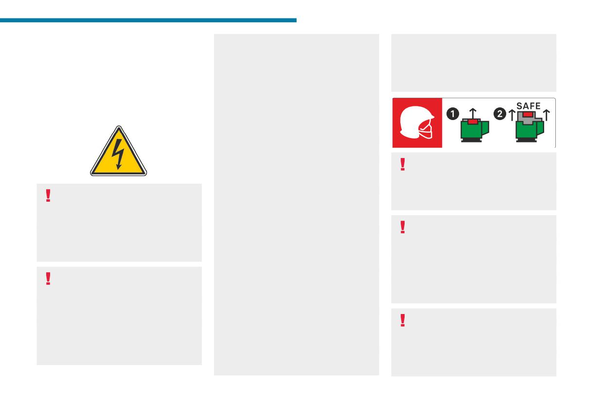
This label is intended solely for use by
- Never work with cutting and forming
firefighters and maintenance services in
tools or heat sources near high voltage
the event of any work on the vehicle.
components and cables.
The rechargeable hybrid powertrain uses
No other person must touch the device shown
In case of low level of fluid in the cooling
a voltage of between 240 V and 400 V.
on this label.
tank, the refilling shall only be performed in a
This system may be hot both when the
qualified and trained workshop to verify that
ignition is on and after switching it off.
the leakage is not in the traction battery.
In the event of an accident or impact
Comply with the warning messages shown
Any intervention on the high voltage system
to the vehicle’s underbody
on the labels, particularly inside the charging
must be carried out by qualified persons in
In these situations, the electrical circuit or the
flap.
workshops qualified and approved to carry
traction battery can be seriously damaged.
out this type of work.
Stop as soon as it is safe to do so and switch
High voltage system voltage is
Damage to the vehicle or the traction battery
off the ignition.
dangerous and can cause burns or other
could result in the leakage of toxic gases or
Contact a PEUGEOT dealer or a qualified
injuries or even fatal electric shock.
fluids either immediately or later. PEUGEOT
workshop.
Since damage to high voltage components is
recommends that you:
not visible, PEUGEOT recommends that you:
- Always inform the fire and emergency
When washing
- Never touch the components, damaged
services in the event of an incident, warning
Before washing the vehicle, always
or not, and never let your jewelry or other
that the vehicle is equipped with a traction
check that the charging flap is closed
metallic objects come into contact with these
battery.
correctly.
components.
- Never touch the liquids leaking from the
Never wash the vehicle while the battery is
traction battery.
on charge.
179
Practical information
High-pressure washing
To preserve the mileage of your vehicle
Traction battery overheating
To avoid damaging the electrical
and the durability of your traction battery,
If the following warning lamps
components, it is expressly prohibited to
PEUGEOT recommends that you:
appear, accompanied by the
use high-pressure washing in the engine
- Do not fully charge the battery of your
display of a message and an audible signal, it is
compartment or under the body.
electric vehicle daily (charge the traction
required to:
Do not use a pressure greater than 80 bar
battery below 80% as often as possible).
► Stop the vehicle as soon as possible in the
when washing the bodywork.
- Do not completely discharge the battery.
best conditions of safety.
- Do not store the vehicle for a long period
► Switch off the ignition.
Never allow water or dust to enter the
of non-use (more than 12 hours) when the
► Evacuate the vehicle as quickly as possible
connector or charging nozzle - risk of
traction battery has a low or high charge level.
and move to a safe distance.
electrocution or fire!
Prefer a charge level between 20 and 40%.
► Call the fire department and/or the
Never connect / disconnect the charging
- Limit the use of fast charging.
emergency services and tell them that the
nozzle or cable with wet hands - risk of
- Do not expose the vehicle to temperatures
vehicle is an electric one.
electrocution!
below -30°C and above +60°C for more than
Danger of death / Risk of serious
24 hours.
injury
- Avoid charging the vehicle at negative
Traction battery
A chain reaction can occur up to a traction
temperatures (except if the vehicle ran more
battery fire.
The Li-ion (Lithium-ion) traction battery stores
than 20 minutes) or above +30°C.
the electrical energy needed to propel the
- Do not use the vehicle's traction battery as
vehicle.
a generator of energy.
Disposal of the traction battery
It is located under the rear seats.
- Do not use a generator to recharge your
The traction battery is designed for the life of the
The traction battery's range varies depending
vehicle's traction battery.
vehicle if the recommendations of PEUGEOT
on the type of driving, the route, the use of
are followed.
thermal comfort equipment and the ageing of its
In the event of damage to the traction
If it becomes necessary to replace the battery,
components.
battery
contact the PEUGEOT dealer for instructions on
The traction battery ageing depends on
It is strictly prohibited to work on the vehicle
its disposal. Improper disposal carries the risk of
several factors, such as climatic
yourself.
severe burns, electric shock, and damage to the
conditions and the distance travelled.
Do not touch liquids coming from the battery,
environment.
and in the event of skin contact with these
In accordance with regulations, PEUGEOT
products, wash abundantly with water and
ensures a second life or recycling of this
contact a doctor as soon as possible.
component in collaboration with qualified
Contact a PEUGEOT dealer or a qualified
operators.
workshop to have the system checked.
180
Practical information
Charging flap
of local electrical installations with the charging
7
cable.
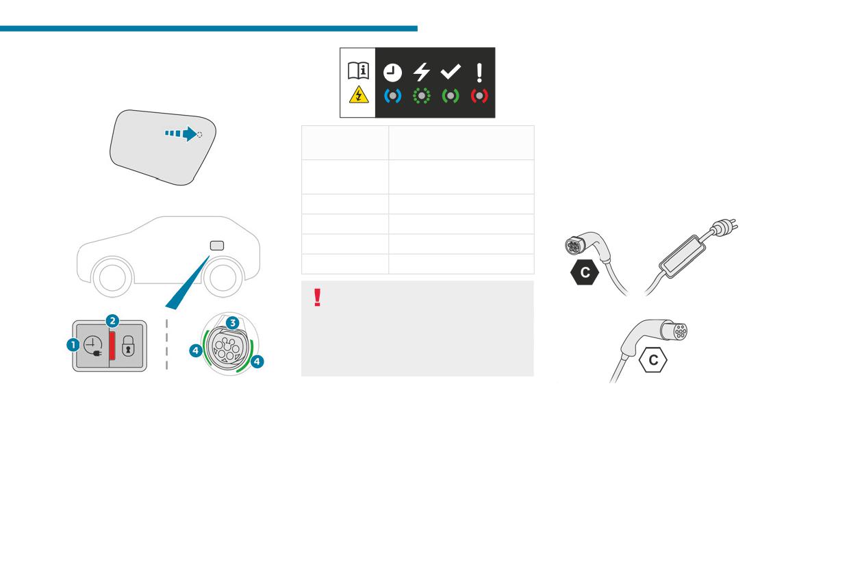
The charging flap is located on the rear left-hand
Contact a PEUGEOT dealer or a qualified
side of the vehicle.
workshop to obtain the appropriate charging
cable(s).
Status of light
Meaning
Identification labels on charging
guides
sockets/connectors
Fixed white
Welcome lighting when flap
Identification labels are affixed to the vehicle,
is opened
charging cable and charger to inform the user
► Press the top rear of the flap to open it.
Fixed blue
Deferred charging
about which device needs to be used.
Flashing green
Charging
Fixed green
Charging complete
Fixed red
Malfunction
In case of impact, even light, against the
charging flap, do not use it.
Do not dismantle or modify the charging
connector - risk of electrocution and/or fire!
Contact a PEUGEOT dealer or a qualified
workshop.
1. Deferred charging activation button
The meaning of each identification label is as
Charging cables, sockets
2. Indicator lamp confirming that the nozzle is
follows:
locked into the charging connector.
and chargers
Fixed red: nozzle correctly positioned and
The traction battery can be charged using
locked.
several different types of cables.
Flashing red: nozzle incorrectly positioned or
The charging cable supplied with the vehicle is
locking not possible.
compatible with the electrical installations of the
3. Charging connector
country of sale. If you are travelling abroad, refer
4. Light guides
to the following tables to check the compatibility
181
Practical information
Identification label
Location
Configuration
Power type/Voltage range
Charging connector (vehicle side)
TYPE 2
AC
C
< 480 Vrms
Charging socket (charger side)
TYPE 2
AC
C
< 480 Vrms
Types of charging
Cable type
Compatibility
Specifications
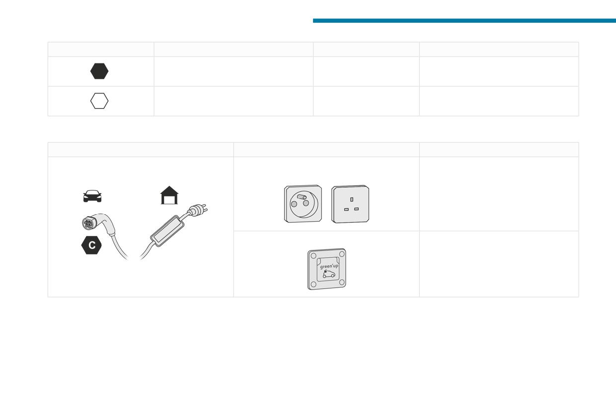
Mode 2 charging cable with integrated control
Conventional electrical socket (depending on
Charge limited to a maximum of 10 A.
unit
country).
"Green'Up" type socket.
Charge limited to a maximum of 16 A.
Identification label C on the charging connector
(vehicle side).
182
Practical information
Cable type
Compatibility
Specifications
7
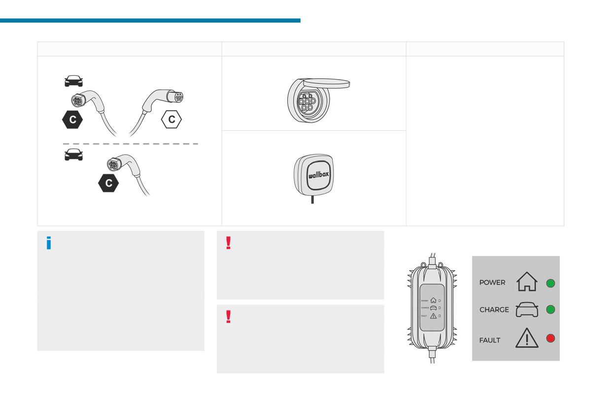
Mode 3 charging cable
Accelerated charging unit socket.
Charge limited to a maximum of 32 A.
Wallbox accelerated charging unit.
Identification labels C on the charging connector
(vehicle side) and on the socket (charger side).
The estimated charging time is indicated
Domestic charging cable (mode 2)
Control unit (mode 2)
on the instrument panel when the vehicle
It is essential to avoid damaging the
is connected. It may vary depending on
cable and to keep it intact.
various factors such as the outside
In the event of damage, do not use it and
temperature or the quality of the electricity
contact a PEUGEOT dealer or a qualified
supply.
workshop to replace it.
If the outside temperature is below -10°C, it
is recommended to connect the vehicle as
Accelerated charging unit (mode 3)
soon as possible as the charging time may
Do not dismantle or modify the
increase significantly. The traction battery
accelerated charging unit - risk of
may not charge fully.
electrocution and/or fire!
To find out how it is used, please refer to the
accelerated charging unit's user instructions.
Type 1
183
Practical information
- If the circuit-breaker has tripped, contact a
6.
Never use this charging cable if it is
professional to check that your electricity supply
defective or in any way damaged.
is compatible and carry out any necessary
7.
Never attempt to repair or open this
repairs.
charging cable. It contains no repairable
- If the circuit-breaker has not tripped, stop
parts - replace the charging cable if it is
using the charging cable and contact a
damaged.
PEUGEOT dealer or a qualified workshop.
8.
Never immerse this charging cable in water.
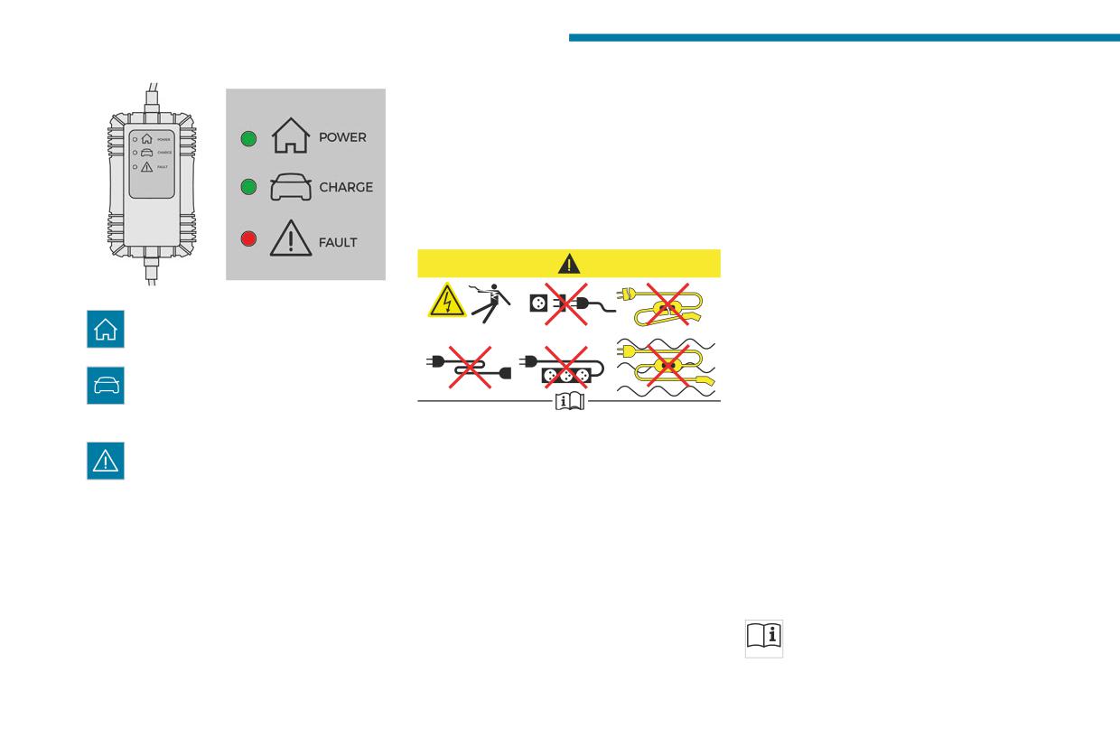
Type 1 control unit label
9.
Never use this charging cable with an
- Recommendations
extension cable, a multi-plug socket, a
conversion adaptor or on a damaged
electrical socket.
10.
Do not unplug the plug from the wall as a
Type 2
means of stopping charging.
POWER
11.
Do not force the connector if it is locked into
Green: electrical connection established;
the vehicle.
charging can begin.
12.
Immediately stop charging, by locking and
CHARGE
then unlocking the vehicle using the remote
Flashing green: charging in progress or
control key, if the charging cable or wall
temperature pre-conditioning activated.
1. Refer to the handbook before use.
socket feel burning hot to the touch.
Fixed green: charging complete.
2. Incorrect use of this charging cable may
13.
This charging cable includes components
FAULT
result in fire, property damage and serious
liable to cause electrical arcing or sparks.
Red: fault; charging not permitted or must
injury or death by electrocution!
Do not expose to flammable vapours.
be stopped immediately. Check that everything
3. Always use a correctly earthed power
14.
Only use this charging cable with PEUGEOT
is connected correctly and that the electrical
socket, protected by a 30 mA residual
vehicles.
system is not faulty.
current device.
15.
Never plug the cable into the wall socket (or
If the indicator lamp does not go off, contact a
4. Always use an electrical socket protected
unplug it) with wet hands.
PEUGEOT dealer or a qualified workshop.
by a circuit-breaker appropriate for the
Upon plugging the charging cable into a
Type 2 control unit label
electrical circuit’s current rating.
domestic socket, all of the indicator lamps come
- Recommendations
5. The weight of the control unit must not be
on briefly.
borne by the electrical socket, plug and
Refer to the handbook before use.
If no indicator lamps come on, check the
cables.
domestic socket's circuit-breaker.
184
Practical information
6.
Never attempt to repair or open this
13. Never plug the cable into the wall socket (or
7
charging cable. It contains no repairable
unplug it) with wet hands.
parts - replace the charging cable if it is
14. Do not force the connector if it is locked into
damaged.
the vehicle.
1.
Incorrect use of this charging cable may
7.
Never immerse this charging cable in water.
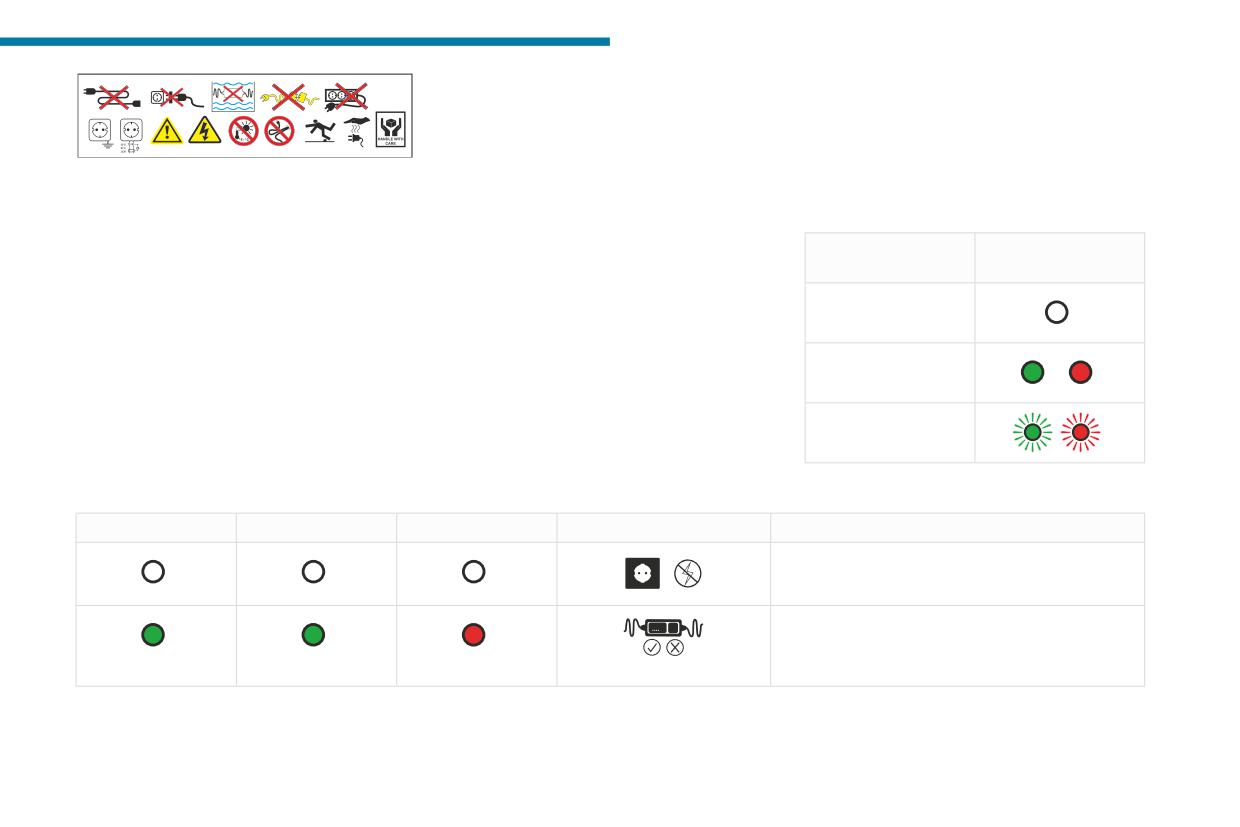
Type 2 control unit label - State of
result in fire, property damage and serious
8.
Never use this charging cable with an
indicator lamps
injury or death by electrocution!
extension cable, a multi-plug socket, a
2.
Always use a correctly earthed power
conversion adaptor or on a damaged
State of the
socket, protected by a 30 mA residual
electrical socket.
indicator lamp
current device.
9.
Do not unplug the plug from the wall as a
3.
Always use an electrical socket protected
means of stopping charging.
Off
by a circuit-breaker appropriate for the
10.
Immediately stop charging, by locking and
electrical circuit’s current rating.
then unlocking the vehicle using the remote
On
4.
The weight of the control unit must not be
control key, if the charging cable or wall
borne by the electrical socket, plug and
socket feel burning hot to the touch.
cables.
11.
This charging cable includes components
Flashing
5.
Never use this charging cable if it is
liable to cause electrical arcing or sparks.
defective or in any way damaged.
Do not expose to flammable vapours.
12.
Only use this charging cable with PEUGEOT
vehicles.
POWER
CHARGE
FAULT
Symbol
Description
Not connected to the power supply or power is not
available from the infrastructure.
The control unit is currently performing a self-test.
(green)
(green)
(red)
185
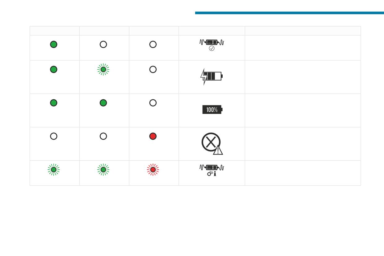
Practical information
POWER
CHARGE
FAULT
Symbol
Description
Connected only to the infrastructure or to the
infrastructure and to the Electric Vehicle (EV) but
no charging in progress.
(green)
Connected to the power supply and to the Electric
Vehicle (EV).
The EV is on charge or in a temperature pre-
(green)
(green)
conditioning sequence.
Connected to the power supply and to the Electric
Vehicle (EV).
The EV is waiting for charging or the charging of
(green)
(green)
the EV is completed.
Control unit malfunction. No charging allowed.
If an error indicator reappears after a manual reset,
the control unit must be checked by a PEUGEOT
(red)
dealer before the next charge.
The control unit is in diagnostic mode.
(green)
(green)
(red)
Manual reset procedure
The control unit can be reset by simultaneously disconnecting the charging connector and the wall socket.
Then, reconnect the wall socket first. For more information, refer to the handbook.
186
Practical information
Charging the traction
vehicle breaking down and can lead to
Precautions
7
accidents or serious injuries. ALWAYS make
Rechargeable hybrid vehicles have
battery (Rechargeable
sure the traction battery has a sufficient
been developed in accordance with the
charge level.
hybrid)
recommendations for maximum electromagnetic
field limits established by the ICNIRP
For a full charge, follow the charging procedure
Low charging / Parking
(International Commission on Non-Ionizing
without interrupting it, until it stops automatically.
If the outside temperature is negative,
Radiation Protection - 1998 Guidelines).
Charging may be performed either immediately
it is recommended not to park your vehicle
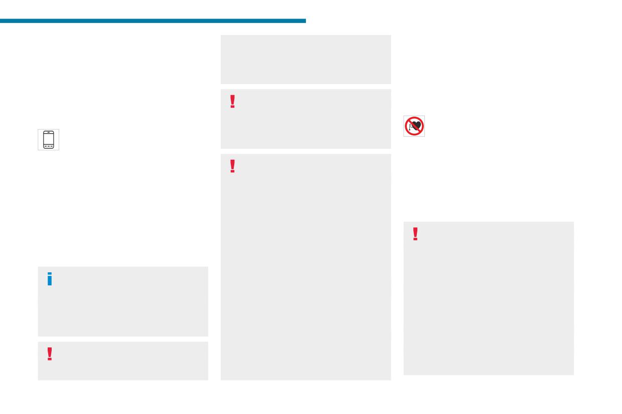
Wearers of pacemakers or equivalent
(by default) or deferred.
outside for several hours at a low charging
devices should consult a doctor to
Deferred charging is set via the touch
(less than 20%).
enquire about any applicable precautionary
screen or the MYPEUGEOT APP
measures, or contact the manufacturer of their
application.
Vehicle in storage for more than
implanted electronic medical device to check that
When the vehicle is connected, the following
1 month
it is guaranteed to operate in an environment
information is displayed on the instrument panel:
In the event of a long period of non-use of
compliant with the ICNIRP guidelines.
- Traction battery charge status (%).
the vehicle (beyond 4 weeks) without the
If in doubt, during charging, do not remain
- Remaining range (miles or km).
possibility of charging when restarting, the
inside or near the vehicle, near the charging
- Estimated charging time (calculation may take
self-discharge may make it impossible to
cable or the charging unit, even for a short time.
a few seconds).
restart if the traction battery charge level
- Charging speed (miles or km gained per hour).
Before charging
is a low or very low, especially at negative
After the instrument panel has been put into
Depending on the context:
ambient temperatures. ALWAYS make sure
standby mode, this information can be displayed
► Have a professional check that the
that the traction battery has a charge between
again by unlocking the vehicle or opening a door.
electrical system to be used complies with
20% and 40% if you do not plan to use your
applicable standards and is compatible with
It is also possible to monitor the charging
vehicle for several weeks.
the vehicle.
progress using the MYPEUGEOT APP
Do not connect the charging cable.
► Have a professional electrician install
application.
Always park the vehicle in a place with
a dedicated domestic power socket or
For more information on Remotely
temperatures between -10°C and 30°C
accelerated charging unit (Wallbox)
operable additional functions, refer to the
(parking in a place with extreme temperatures
compatible with the vehicle.
corresponding section.
can damage the traction battery).
Use the charging cable supplied with the
Refer to the 12 V battery/Accessory
vehicle.
Low charging / Driving
batteries - With rechargeable hybrid
For more information, contact a PEUGEOT
Driving when the charge level of the
engines section for the battery disconnection
dealer or a qualified workshop.
traction battery is too low can lead to the
procedure.
187
Practical information
During charging
► Press on the rear of the charging flap to open
If this is not the case, charging has not started;
As a safety measure, the engine will
it and check that there are no foreign bodies on
restart the procedure, ensuring that all of the
not start if the charging cable is plugged into
the vehicle's charging connector.
connections are properly established.
the connector on the vehicle. A warning is
The light guides in the flap come on white.
The red indicator lamp in the flap comes on to
displayed on the instrument panel.
indicate that the nozzle is locked.
Domestic charging (mode 2)
While charging is in progress, unlocking the
Accelerated charging (mode 3)
vehicle will cause the charging to stop.
If no action is taken on one of the openings
(door or boot) or on the charging nozzle, the
vehicle will lock again after 30 seconds and
charging will resume automatically.
Never work under the bonnet:
- Some areas remain very hot, even an hour
after charging ends - risk of burns!
► Follow the accelerated charging unit
- The fan may start at any time - risk of cuts
(Wallbox) user instructions.
or strangulation!
► Remove the protective cover from the
charging nozzle.
After charging
► Insert the nozzle into the vehicle's charging
Check that the charging flap is closed.
connector.
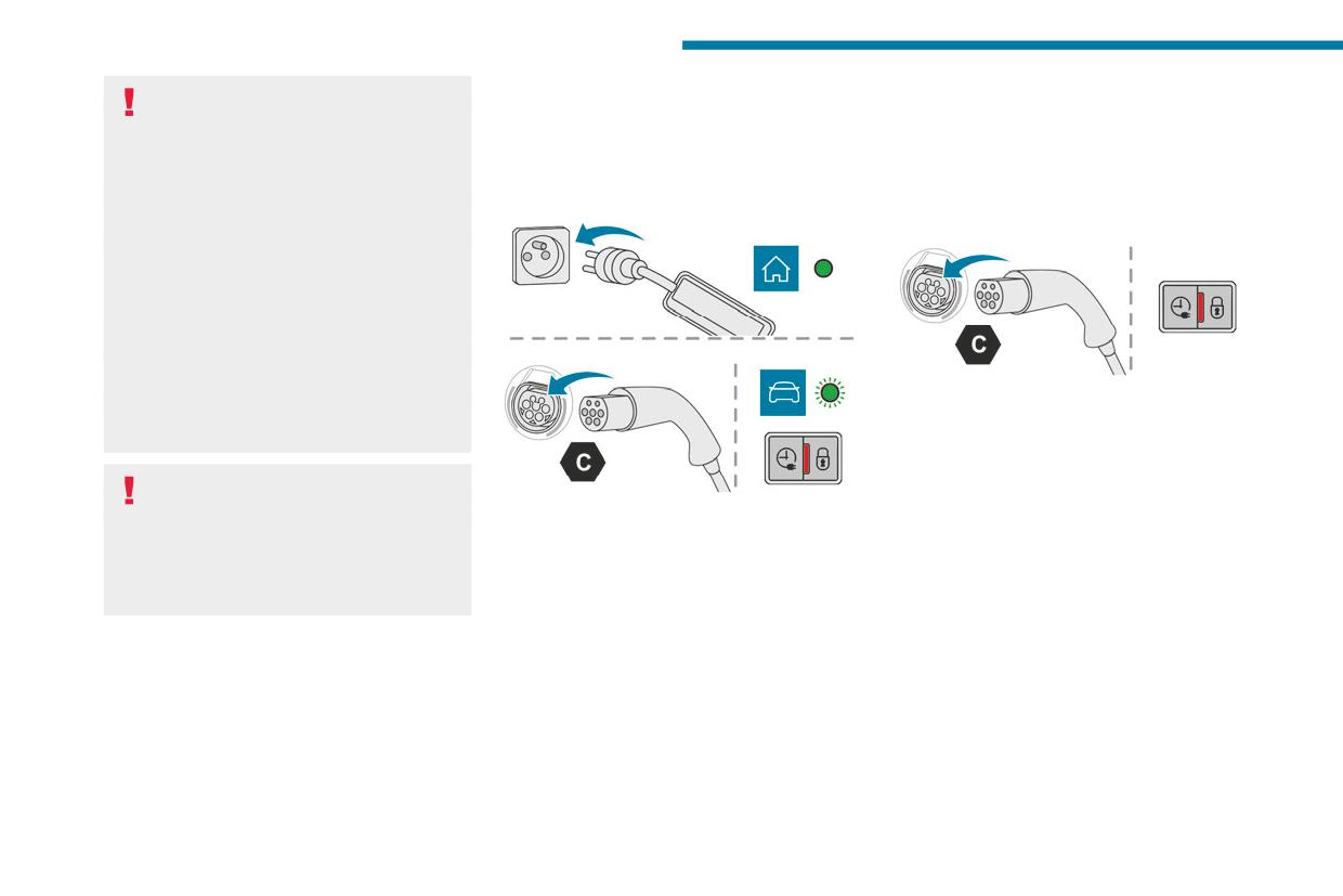
► First, connect the charging cable from the
Do not leave the cable connected to the
The start of charging is confirmed by the flashing
control unit to the domestic socket.
domestic power socket - risk of short-circuit
of the green light guides in the flap.
When the connection is made, all of the indicator
or electrocution in the event of contact with or
If this is not the case, charging has not
lamps on the control unit light up, then only the
immersion in water!
started; restart the procedure ensuring that all
POWER indicator lamp remains on in green.
► Remove the protective cover from the
connections are properly established.
charging nozzle.
The red indicator lamp in the flap comes on to
Charging procedure
► Insert the nozzle into the vehicle's charging
indicate that the nozzle is locked.
connector.
Connection
Deferred charging
The start of charging is confirmed by the flashing
► Before charging, check that the gear selector
of the green light guides in the flap and the
By default, the deferred charging start time is set
is in mode P and the ignition is off, otherwise
flashing of the CHARGE indicator lamp in green
to midnight.
charging is impossible.
on the control unit.
Depending on equipment, this time can be
changed.
188
Practical information
Settings
Before disconnecting the nozzle from the
Towing device
7
charging connector:
With PEUGEOT Connect Nav
Load distribution
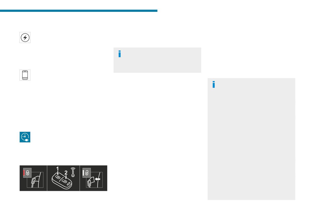
► If the vehicle is locked, unlock it.
► In the Energy touch screen menu,
► Distribute the load in the trailer so that the
► If the vehicle is unlocked, lock it and then
select the Charge page.
heaviest items are as close as possible to the
unlock it.
► Set the charging start time.
axle, and the nose weight approaches the
► Press OK.
If selective unlocking of the doors is
maximum permitted without exceeding it.
The setting is saved in the system.
activated, press the unlocking button on
Air density decreases with altitude, thus reducing
With PEUGEOT Connect Radio or PEUGEOT
the remote control twice to disconnect the
engine performance. The maximum towable load
Connect Nav
nozzle.
must be reduced by 10% per 1,000 metres of
You can also programme the deferred
altitude.
charging function at any time from a
The red indicator lamp in the flap goes out to
smartphone via the MYPEUGEOT APP
confirm that the nozzle is unlocked.
Use genuine towing devices and wiring
application.
► Within 30 seconds, remove the charging
harnesses approved by PEUGEOT. We
For more information on Remotely operable
nozzle.
recommend having them fitted by a
additional functions, refer to the corresponding
PEUGEOT dealer or a qualified workshop.
Domestic charging (mode 2)
section.
If not fitted by a PEUGEOT dealer, they must
The end of charging is confirmed when the
still be fitted in accordance with the vehicle
Activation
green CHARGE indicator lamp on the control
manufacturer's instructions.
► After programming the deferred charging,
unit comes on fixed and the green light guides in
Important: if the vehicle has a motorised
connect the vehicle to the desired charging
the flap come on fixed.
tailgate and Hands-Free Tailgate Access
equipment.
► After disconnection, replace the protective
function, and a towing device has been fitted
► Press this button in the flap within one
cover over the nozzle and close the charging
outside the PEUGEOT dealer network, it
minute to activate the deferred charging
flap.
is essential to visit a PEUGEOT dealer or
(confirmed by the light guides coming on in
► Disconnect the control unit's charging cable
a qualified workshop to have the detection
blue).
from the domestic socket.
system recalibrated - risk of malfunction of the
Accelerated charging (mode 3)
Hands-Free Tailgate Access function.
Disconnection
The end of charging is confirmed by the
Certain driving or manoeuvring aid functions
accelerated charging unit (Wallbox) and when
are automatically deactivated while an
the green light guides in the flap come on fixed.
approved towing system is in use.
► After disconnection, replace the nozzle on to
For more information about driving with a
the charging unit and close the charging flap.
towing device fitted to a trailer and associated
with the Trailer stability assist, refer to the
corresponding section.
189
Practical information
Comply with the maximum authorised
Towing device with quickly
towable weight, as indicated on your
vehicle's registration certificate, on the
detachable towball
manufacturer's label and in the Technical
data section of this guide.
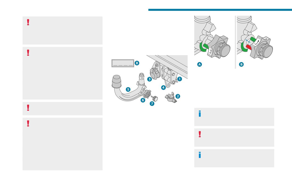
Presentation
No tools are required to install or remove this
If using accessories attached to the
genuine towing device.
towing device (e.g. bicycle carriers, tow
boxes):
- Comply with the maximum authorised nose
weight.
A. Locked position (the green marks are
- Do not transport more than 4 conventional
opposite each other); the wheel is in contact
bicycles or 2 electric bicycles.
with the towball (no gap).
When loading bicycles onto a bicycle carrier
B. Unlocked position (red mark opposite
on a towball, be sure to place the heaviest
the green mark); the wheel is no longer
bicycles as close as possible to the vehicle.
in contact with the towball (gap of around
5 mm).
Observe the legislation in force in the
country where you are driving.
1. Carrier
Affix the enclosed label in a clearly visible
2. Protective plug
location, close to the carrier or in the
Vehicle equipped with motorised
3. Connection socket
boot.
tailgate with hands-free function
4. Safety eye
(Hands-Free Tailgate Access)
5. Detachable towball
Trailers with LED lamps are not
To avoid unintentionally opening the
6. Locking/unlocking wheel
compatible with the wiring harness of this
motorised tailgate when operating the towing
7. Security key lock
device.
device:
8. Label to note the key references
- Deactivate this function in advance in the
To ensure complete safety while driving
vehicle's configuration menu.
with a Towing device, refer to the
- Or remove the electronic key from the
corresponding section.
recognition zone, with the tailgate closed.
190
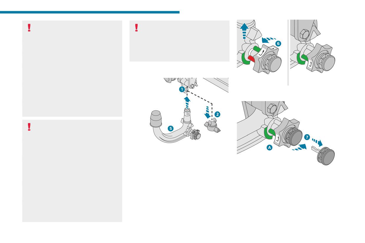
Practical information
Before each use
After use
7
Verify that the towball is correctly fitted,
When travelling without a trailer or
checking the follow points:
load carrier, remove the towball and fit the
- The green mark on the wheel is in line with
protective plug into the carrier, to provide
the green mark on the towball.
clear visibility of the number plate and/or its
- The wheel is in contact with the towball
lighting.
(position A).
- The security key lock is closed and the
Fitting the towball
key removed; the wheel can no longer be
operated.
- The towball must not be able to move in
► The wheel 6 rotates a quarter turn anti-
its carrier; test by attempting to shake it with
clockwise; take care to keep your hands clear!
your hand.
If the towball is not locked, the trailer can
become detached - risk of an accident!
During use
Never release the locking system with a
trailer or load carrier on the towball.
Never exceed the maximum authorised
weight for the vehicle - the Gross Train
► Below the rear bumper, remove the protective
Weight or GTW.
plug 2 from the carrier 1.
Always comply with the maximum authorised
► Insert the end of the towball 5 into the carrier
load on the towing device: if it is exceeded,
1 and push it upwards; it will lock into position
► Check that the mechanism has correctly
this device may become detached from the
automatically.
locked into place (position A).
vehicle - risk of an accident!
► Close the lock 7 using the key.
Before driving, check the headlamp height
► Remove the key. The key cannot be removed
adjustment and check that the lamps on the
while the lock is open.
trailer operate correctly.
► Clip the cap onto the lock.
For more information on Headlamp height
adjustment, refer to the corresponding
section.
191
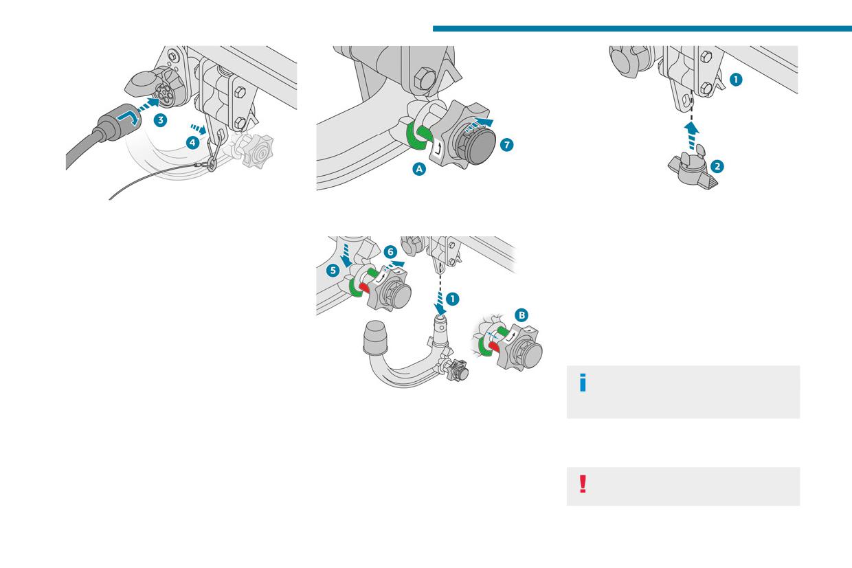
Practical information
► Remove the protective cover from the
► Insert the key into the lock 7.
► Replace the protective plug 2 into the
towball.
► Open the lock using the key.
carrier 1.
► Attach the trailer to the towball.
► Stow the towball in its bag to protect it from
► Attach the cable on the trailer to the safety
knocks and dirt.
eye 4 on the carrier.
► Insert the trailer plug and rotate it by a
Maintenance
quarter turn to connect it to the connection
Correct operation is only possible if the towball
socket 3 on the carrier.
and its carrier are kept clean.
Before cleaning the vehicle with a high-pressure
Removing the towball
jet wash, the towball must be removed and the
► Grasp the trailer's plug, perform a quarter
protective plug fitted to the carrier.
turn and pull to disconnect it from the connection
Work on the towing device
socket 3 on the carrier.
Contact a PEUGEOT dealer or a
► Detach the trailer's safety cable from the
► Hold the towball 5 firmly in one hand; using
qualified workshop.
safety eye 4 on the carrier.
the other hand, pull and turn the wheel 6 fully in
► Unhitch the trailer from the towball.
a clockwise direction until it stops; do not release
► Replace the protective cover over the towball.
the wheel.
Roof bars
► Remove the cap from the lock and press it
► Extract the towball from the base of its
onto the head of the key.
carrier 1.
As a safety measure and to avoid
► Release the wheel; it automatically locks in
damaging the roof, it is essential to use
the unlocked position (position B).
192
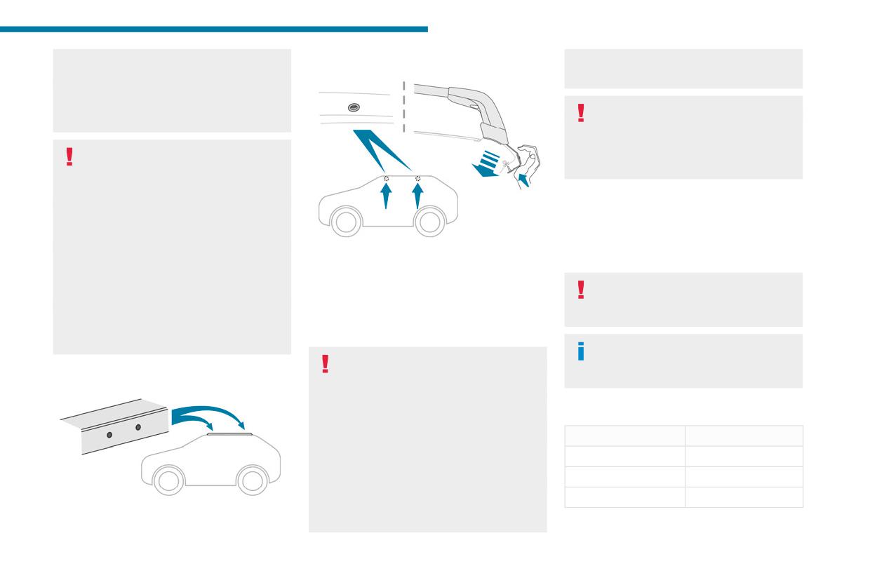
Practical information
transverse roof bars approved for your
Direct fitting on roof
Remove the roof bars once they are no longer
7
vehicle.
needed.
Observe the instructions on fitting and use
contained in the guide supplied with the roof
Sunroof
bars.
Check that the load does not protrude
below the roof bars, so that it does not
Maximum load distributed over the
impede movement of the sunroof - risk of
transverse roof bars, for a loading height
major damage!
not exceeding 40 cm (except bicycle carrier):
80 kg.
As this value may change, please verify the
Snow chains
maximum load quoted in the guide supplied
In wintry conditions, snow chains improve
with the roof bars.
The transverse bars must only be fixed at the
traction as well as the behaviour of the vehicle
If the height exceeds 40 cm, adapt the speed
four anchorage points located on the roof frame.
when braking.
of the vehicle to the profile of the road to
These points are concealed by the vehicle doors
avoid damaging the roof bars and the fixings
Snow chains must be fitted only to the
when the doors are closed.
on the vehicle.
front wheels. They must never be fitted to
The roof bar fixings have a stud which must be
Be sure to refer to national legislation in order
"space-saver" type spare wheels.
inserted into the opening of each anchorage
to comply with the regulations for transporting
point.
objects that are longer than the vehicle.
Observe the legislation in force in your
Recommendations
country relating to the use of snow
Distribute the load uniformly, taking care
chains and maximum authorised speeds.
Fitting on longitudinal bars
to avoid overloading one of the sides.
Arrange the heaviest part of the load as close
Use only chains designed to be fitted to the type
as possible to the roof.
of wheel fitted to the vehicle:
Secure the load firmly.
Original tyre size
Maximum link size
Drive gently: the vehicle will be more
215/65 R17
9 mm
susceptible to the effects of side winds and its
stability may be affected.
225/55 R18
9 mm
Regularly check the security and tight
205/55 R19
9 mm
fastening of the roof bars, at least before each
The transverse bars must be fixed at the
trip.
markings located on the longitudinal bars.
193
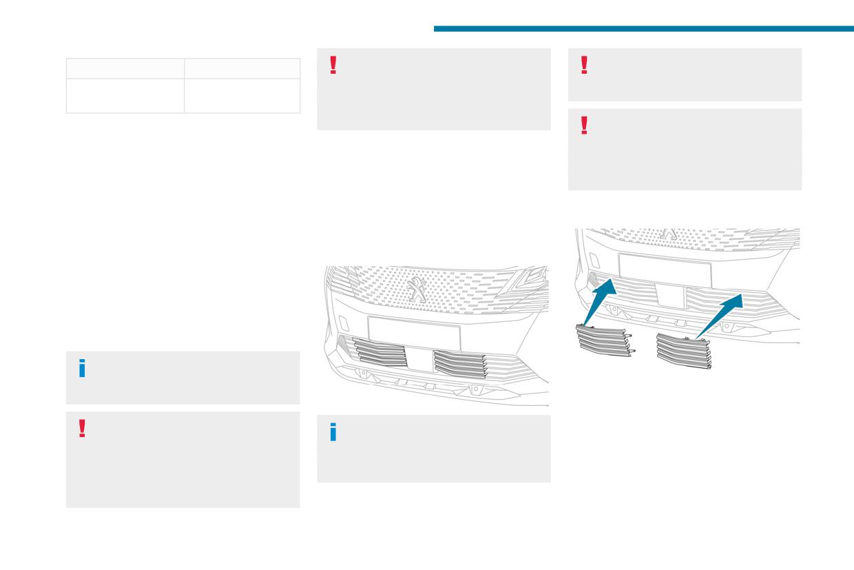
Practical information
Rechargeable hybrid vehicles
Before any operation, ensure that the
Original tyre size
Maximum link size
The use of snow chains is only
engine is off and the cooling fan has
235/50 R19
Not suitable for
authorised on the front wheels.
stopped.
chains
The driving mode selector must be on the
4WD position (depending on version).
It is essential to remove them when:
For more information on snow chains, contact a
- the outside temperature exceeds
PEUGEOT dealer or a qualified workshop.
10°C.
Very cold climate screen
- recovery is in progress.
Installation tips
- the speed is above 75 mph (120 km/h).
► To fit the snow chains during a journey, stop
(Depending on country of sale)
the vehicle on a flat surface at the side of the
This removable device prevents the
road.
accumulation of snow around the radiator
Fitting
► Apply the parking brake and position any
cooling fan.
wheel chocks under the wheels to prevent
It consists of two elements to be attached to the
movement of the vehicle.
front bumper.
► Fit the snow chains following the instructions
provided by the manufacturer.
► Move off gently and drive for a few moments,
without exceeding 31 mph (50 km/h).
► Stop the vehicle and check that the snow
chains are correctly tightened.
It is strongly recommended that you
practise fitting the snow chains on a level
► Hold the corresponding screen in front of the
and dry surface before setting off.
lower grille of the bumper.
► First insert the upper and side fixing brackets
Avoid driving with snow chains on roads
In case of difficulty with installation/
into the bumper.
that have been cleared of snow to avoid
removal
► Tilt the screen downwards to engage the
damaging the vehicle's tyres and the road
Contact a PEUGEOT dealer or a qualified
lower part of the screen into the bumper.
surface. If the vehicle is fitted with alloy
workshop.
► Check that the unit is firmly held by pressing
wheels, check that no part of the chain or its
around the edges.
fixings is in contact with the wheel rim.
Repeat these operations for the other screen.
194
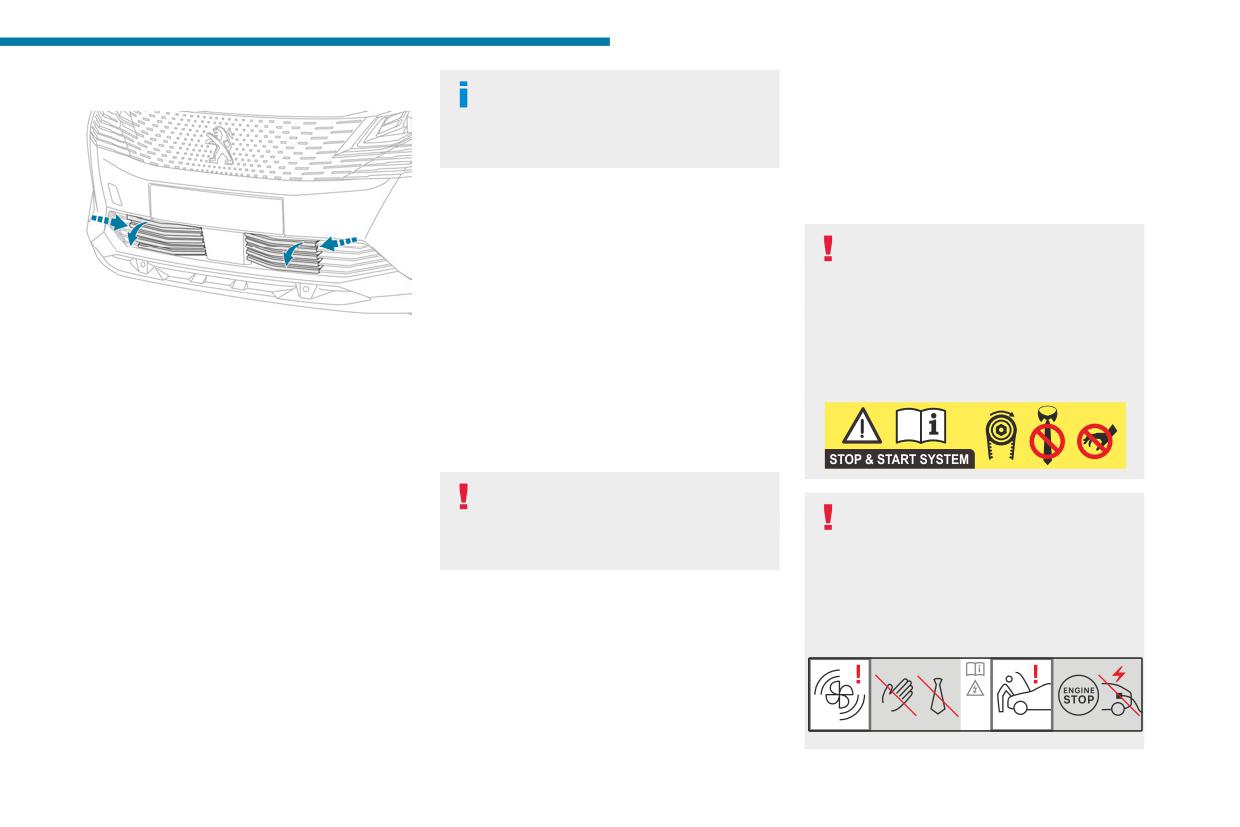
Practical information
Removing
If a telephone call is in progress at the
functions, such as the air conditioning and the
7
time, it will be maintained for around 10
heated rear screen.
minutes via the audio system’s hands-free
The deactivated functions are reactivated
system.
automatically as soon as conditions permit.
Exiting the mode
Bonnet
These functions are automatically reactivated the
Stop & Start / e-Auto mode
next time the vehicle is used.
Before doing anything under the bonnet,
To restore the use of these functions
you must switch off the ignition to avoid any
immediately, start the engine and let it run:
risk of the engine restarting automatically.
- For less than 10 minutes, to use the
Take care with objects or clothing that could
► Insert a finger into the notch in the upper part
equipment for approximately 5 minutes.
be caught in the blades of the cooling fan
of the screen.
- For more than 10 minutes, to use the
or in certain moving components - risk of
► Pull towards you to unclip the unit.
equipment for approximately 30 minutes.
strangulation and serious injury!
Repeat these operations for the other screen.
Let the engine run for the specified duration to
ensure that the battery charge is sufficient.
To recharge the battery, avoid repeatedly or
Energy economy mode
continuously restarting the engine.
This system manages the duration of use of
A flat battery prevents the engine from
certain functions, in order to conserve a sufficient
starting.
Rechargeable hybrid vehicles
level of charge in the battery with the ignition off.
For more information on the 12 V battery,
Before any work is carried out under the
After switching off the engine and for a maximum
refer to the corresponding section.
bonnet, it is essential to switch off the ignition
cumulative period of around 30 minutes, you can
and disconnect the charging connector nozzle
continue to use functions such as the audio and
if it is connected, check that the READY
telematics system, dipped beam headlamps or
Load reduction mode
indicator lamp is off on the instrument panel
courtesy lamps.
and wait 4 minutes - risk of serious injury!
This system manages the use of certain
Selecting the mode
functions according to the level of charge
A confirmation message is displayed when
remaining in the battery.
energy economy mode is entered, and the active
When the vehicle is being driven, the load
functions are placed on standby.
reduction function temporarily deactivates certain
195
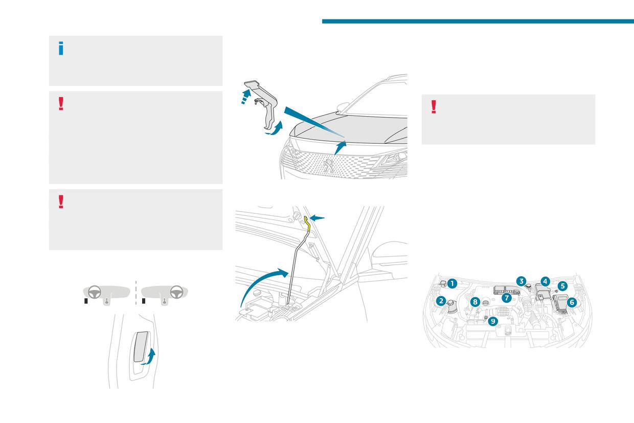
Practical information
The location of the interior bonnet
► Open the left-hand front door.
► Clip the stay in its housing.
release lever prevents the bonnet being
► Pull the interior release lever, located at the
► Lower the bonnet and release it near the end
opened when the left-hand front door is
bottom of the door frame, towards you.
of its travel.
closed.
► Pull on the bonnet to check that it is locked
correctly.
When the engine is hot, handle the
Because of the presence of electrical
exterior safety catch and the bonnet stay
equipment under the bonnet, it is strongly
with care (risk of burns), using the protected
recommended that exposure to water (rain,
area.
washing, etc.) be limited.
When the bonnet is open, take care not to
damage the safety catch.
Do not open the bonnet under very windy
Engine compartment
conditions.
The engine shown here is an example for
► Lift the exterior safety catch and raise the
illustrative purposes only.
Cooling of the engine when stopped
bonnet.
The locations of the following components may
The engine cooling fan may start after
vary:
the engine has been switched off.
- Air filter.
Take care with objects or clothing that
- Engine oil dipstick.
could be caught in the blades of the fan!
- Engine oil filler cap.
Petrol engine
Opening
► Unclip the stay from its housing and place it
in the support slot to hold the bonnet open.
Closing
► Hold the bonnet and pull out the stay from the
support slot.
196
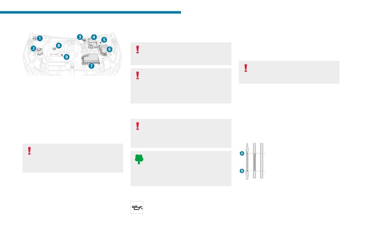
Practical information
Diesel engine
If a level drops significantly, have the
ignition is switched on (for vehicles equipped
7
corresponding system checked by a PEUGEOT
with an electric gauge), or using the dipstick.
dealer or a qualified workshop.
It is normal to top up the oil level between two
services (or oil changes). It is recommended
The fluids must comply with the
that you check the level, and top up if necessary,
Manufacturer's requirements and with
every 3,000 miles (5,000 km).
the vehicle's engine.
In order to maintain the reliability of the
Take care when working under the
engine and emissions control system,
bonnet, as certain areas of the engine
never use additives in the engine oil.
may be extremely hot (risk of burns) and the
1. Screenwash fluid reservoir
cooling fan could start at any time (even with
2. Engine coolant reservoir
Checking using the dipstick
the ignition off).
3. Brake fluid reservoir
For the location of the dipstick, please refer
4. Battery/Fuses
to the illustration of the corresponding engine
5. Remote earth point (-)
Used products
compartment.
6. Fusebox
► Grasp the dipstick by its coloured grip and
7. Air filter
Avoid prolonged contact of used oil or
pull it out completely.
8. Engine oil filler cap
fluids with the skin.
► Wipe the end of the dipstick using a clean,
9. Engine oil dipstick
Most of these fluids are harmful to health and
lint-free cloth.
very corrosive.
Diesel fuel system
This system is under very high pressure.
Do not discard used oil or fluids into
All work must be carried out only by a
sewers or onto the ground.
PEUGEOT dealer or a qualified workshop
Empty used oil into the containers reserved
for this purpose at a PEUGEOT dealer or a
qualified workshop.
► Reinsert the dipstick and push fully down,
Checking levels
then pull it out again to visually check the oil
Check all of the following levels regularly in
Engine oil
level: the correct level is between marks A (max)
accordance with the Manufacturer's service
The level is checked, with the engine
and B (min).
schedule. Top them up if required, unless
having been switched off for at least 30
Do not start the engine if the level is:
otherwise indicated.
minutes and on level ground, either using the oil
- above mark A: contact a PEUGEOT dealer or
level indicator in the instrument panel when the
a qualified workshop.
197
Practical information
- below mark B: top up the engine oil
engine. Risk of fire inside the engine
When the engine is hot, the temperature of the
immediately.
compartment.
coolant is regulated by the fan.
As the cooling system is pressurised, wait at
Oil grade
The oil level indication displayed on the
least one hour after switching off the engine
Before topping up or changing the
instrument panel when the ignition is
before carrying out any work.
engine oil, check that the oil is suitable
switched on is not valid for 30 minutes
In order to avoid the risk of scalding if you need
for your engine and complies with the
following an addition of oil.
to top up in an emergency, wrap a cloth around
recommendations in the service schedule
the cap and unscrew the cap by two turns to
supplied with the vehicle (or available
allow the pressure to drop.
from your PEUGEOT dealer or qualified
Brake fluid
Once the pressure has dropped, remove the cap
workshop).
The level of this fluid should be close to
and top up to the required level.
Use of non-recommended oil may invalidate
the "MAX" mark. If not, check the brake
your warranty in the event of engine failure.
pads for wear.
Screenwash fluid
To know how often the brake fluid should be
Top up to the required level when
Topping up the engine oil level
replaced, refer to the manufacturer's servicing
necessary.
For the location of the engine oil filler cap, please
schedule.
Capacity of the tank:
refer to the corresponding engine compartment
- 5.3 litres for "very cold climate" versions.
Clean the cap before removing it to refill.
illustration.
- 2.2 litres for other versions.
Use only DOT4 brake fluid from a sealed
Never remove the oil filler cap with the
container.
Fluid specification
engine running. Risk of burns and
The fluid must be topped up with a pre-mixed
splashes inside the engine compartment.
Engine coolant
product.
► Add oil in small quantities, avoiding any spills
It is normal to top up this fluid between
In winter (temperatures below zero), a fluid
on engine components (risk of fire).
two services.
containing an anti-freeze agent which is
► Wait a few minutes before checking the level
The check and top-up must only be done with
appropriate for the temperature conditions
again using the dipstick.
the engine cold.
must be used in order to protect the system's
► Top up the level if necessary.
A level of coolant that is too low risks causing
components (pump, tank, ducts, jets).
► After checking the level, carefully screw the
major damage to the engine; the coolant level
Filling with pure water is prohibited in all
oil filler cap back on and push the dipstick back
must be close to the "MAX" mark without ever
circumstances (risk of freezing,
into its tube up to the stop.
going above it.
limescale, etc.).
If the level is close to or below the "MIN" mark, it
The dipstick must be pushed completely
is essential to top it up.
in to prevent oil from spilling onto the
198
Practical information
Diesel fuel additive (Diesel
Otherwise, have them checked by a PEUGEOT
city driving), change it twice as often, if
7
dealer or a qualified workshop.
necessary.
with particle filter)
Only use products recommended by
A clogged passenger compartment filter
On reaching the minimum level in the
PEUGEOT or products of equivalent
can adversely affect air conditioning
particle filter additive tank, this warning
quality and specification.
system performance and generate
lamp comes on fixed, accompanied by an
In order to optimise the operation of
undesirable odours.
audible signal and a warning message.
components as important as those in the
Topping up
braking system, PEUGEOT selects and offers
Air filter
very specific products.
The topping up of this additive must be carried
Depending on the environment and the
out quickly.
use of the vehicle (e.g. dusty atmosphere,
Go to a PEUGEOT dealer or a qualified
12 V battery
city driving), change it twice as often, if
workshop.
The battery does not require any
necessary.
maintenance.
AdBlue® (BlueHDi)
Check regularly that the terminals are correctly
Oil filter
An alert is triggered when the reserve level is
tightened (versions without quick-release
Change the oil filter each time the engine
reached.
terminals) and that the connections are clean.
oil is changed.
For more information on the Indicators and in
particular the AdBlue range indicators, refer to
For more information on the precautions
Particle filter (Diesel)
the corresponding section.
to take before any work on the 12 V
The start of clogging of the particle filter is
To avoid the vehicle being immobilised in
battery, refer to the corresponding section.
indicated by the temporary lighting of this
accordance with regulations, you must top up the
warning lamp, accompanied by an alert
AdBlue tank.
Versions equipped with Stop & Start are
message.
For more information on AdBlue® (BlueHDi),
fitted with a 12 V lead-acid battery of
As soon as traffic conditions allow, regenerate
and in particular the supply of AdBlue, refer to
specific technology and specification.
the filter by driving at a speed of at least
the corresponding section.
Its replacement should be carried out only by
37 mph (60 km/h), with an engine speed above
a PEUGEOT dealer or a qualified workshop.
2,500 rpm, for about 15 minutes (until the
Checks
warning lamp goes out).
Passenger compartment
If it is not possible to reach 37 mph (60 km/h),
Unless otherwise indicated, check these
leave the engine running at idle for about 15
components in accordance with the
filter
minutes, then drive with an engine speed above
Manufacturer's service schedule and according
Depending on the environment and the
2,500 rpm for 15 minutes.
to your engine.
use of the vehicle (e.g. dusty atmosphere,
199
Practical information
Do not switch off the engine until the filter
problem, do not hesitate to have the system
Wheels and tyres
is fully regenerated; repeated intervals
checked by a PEUGEOT dealer or a qualified
The inflation pressure of all tyres,
can degrade the engine oil prematurely.
workshop.
including the spare wheel, must be
Regenerating the filter while the vehicle is
For more information on the Electric
checked on "cold” tyres.
stationary is not recommended.
parking brake, refer to the
The pressures indicated on the tyre pressure
corresponding section.
label are valid for "cold" tyres. If you have driven
Following prolonged operation of the
for more than 10 minutes or more than 6 miles
vehicle at very low speed or at idle, you
(10 kilometres) at over 31 mph (50 km/h), add
may, in exceptional circumstances, notice
Brake pads
0.3 bar (30 kPa) to the values indicated on the
water vapour coming from the exhaust while
Brake wear depends on the style of
label.
accelerating. These emissions have no
driving, particularly in the case of vehicles
Under-inflation increases energy
impact on the vehicle’s behaviour and the
used in town, over short distances. It may be
consumption. Non-compliant tyre
environment.
necessary to have the condition of the brakes
pressures cause tyres to wear prematurely
checked, even between vehicle services.
and have an adverse effect on the vehicle's
New vehicle
Unless there is a leak in the circuit, a drop in the
road holding - risk of accident!
During the first few particle filter
brake fluid level indicates that the brake pads
regeneration operations, you may notice a
are worn.
Driving with worn or damaged tyres reduces the
"burning" smell. This is perfectly normal.
braking and road holding performance of the
After washing the vehicle, moisture, or in
wintry conditions, ice can form on the
vehicle. Regularly check the condition of the
brake discs and pads: braking efficiency may
tyres (tread and sidewalls) and rims as well as
Manual gearbox
the presence of the valve caps.
be reduced. Gently dab the brakes to dry and
The gearbox does not require any
defrost them.
When the wear indicators no longer appear set
maintenance (no oil change).
back from the tread, the depth of the grooves is
less than 1.6 mm; replace the tyres as soon as
Automatic gearbox
Brake disc wear
possible.
/
The gearbox does not require
For information on checking brake disc
Using different size wheels and tyres from those
any maintenance (no oil
wear, contact a PEUGEOT dealer or a
specified can affect the lifetime of tyres, wheel
change).
qualified workshop.
rotation, ground clearance, the speedometer
reading and have an adverse effect on road
Electric parking brake
holding.
This system does not require any routine
Fitting different tyres on the front and rear axles
servicing. However, in the event of a
can cause the ESC to mistime.
200
Practical information
Always mark the direction of rotation on the tyres
consumption of its Diesel engines, PEUGEOT
the Euro 6 standard and the vehicle starts
7
that will be stored when fitting winter or summer
has taken the decision to equip its vehicles with
polluting the environment.
tyres. Store them in a cool, dry place and away
a system that combines SCR (Selective Catalytic
In the event of a confirmed SCR system
from direct exposure to the sun's rays.
Reduction) with a Diesel Particle Filter (DPF) for
malfunction, it is essential to visit a
Winter or 4-seasons tyres can be
the treatment of exhaust gases.
PEUGEOT dealer or a qualified workshop.
identified by this symbol on their
After 685 miles (1,100 km), a device is
sidewalls.
SCR system
automatically activated to prevent the engine
Using a liquid called AdBlue® that contains
from starting.
Shock absorbers
urea, a catalytic converter turns up to 85% of
In both cases, a range indicator indicates
It is not easy for drivers to detect when
the nitrogen oxides (NOx) into nitrogen and
the distance that can be travelled before the
shock absorbers are worn. Nevertheless,
water, which are harmless to health and the
vehicle is stopped.
the shock absorbers have a major impact on
environment.
road holding and braking performance.
The AdBlue® is contained in a special
Freezing of the AdBlue®
For your safety and driving comfort, it is
tank holding about 17 litres.
AdBlue® freezes at temperatures below
important to have them regularly checked by a
Its capacity allows a driving range of
around -11°C.
PEUGEOT dealer or a qualified workshop.
approximately 4,000 miles (6,500 km), which
The SCR system includes a heater for the
may vary considerably depending on your
AdBlue® tank, allowing you to continue driving
Timing and accessory kits
driving style.
in very cold conditions.
The timing and accessory kits are used
An alert system is triggered once the reserve
from the time the engine is started until it
level is reached: it is then possible to drive for a
Supply of AdBlue®
is switched off. It is normal for them to wear over
further 1,500 miles (2,400 km) before the tank is
time.
empty and the vehicle is immobilised.
It is recommended that the AdBlue® be topped
A faulty timing or accessory kit can damage
up as soon as the first alert is issued indicating
For more information on the Warning
the engine, rendering it unusable. Observe the
that the reserve level has been reached.
and indicator lamps and the associated
recommended replacement frequency, stated in
alerts, or the Indicators, please refer to the
For the correct operation of the SCR
distance travelled or time elapsed, whichever is
corresponding sections.
system:
reached first.
- Use only AdBlue® fluid that meets the ISO
22241 standard.
Once the AdBlue® tank is empty, a device
AdBlue® (BlueHDi)
required by law prevents the engine from
- Never transfer AdBlue® to another container
as it would lose its purity.
being restarted.
To respect the environment and ensure
- Never dilute AdBlue® with water.
If the SCR system is faulty, the level of
compliance with the Euro 6 standard, without
emissions from the vehicle will no longer meet
adversely affecting the performance or fuel
201
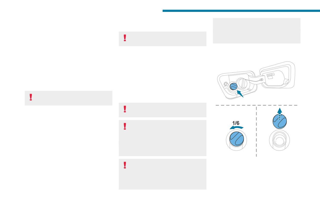
Practical information
You can obtain AdBlue® from a PEUGEOT
vapours have an irritant effect on mucous
electronic key into the passenger
dealer or a qualified workshop, as well as service
membranes (eyes, nose and throat).
compartment.
stations equipped with AdBlue® pumps specially
Switch on the ignition, then wait for 10
Store AdBlue® out of the reach of
designed for passenger vehicles.
seconds before starting the engine.
children, in its original container.
Recommendations on storage
► Press the "START/STOP" button to switch off
the engine.
AdBlue® freezes at about -11°C and deteriorates
Procedure
above +25°C. Containers should be stored in a
Before starting the top-up procedure, ensure that
cool area and protected from direct sunlight.
the vehicle is parked on a flat and level surface.
Under these conditions, the fluid can be kept for
In wintry conditions, ensure that the temperature
at least a year.
of the vehicle is above -11°C. Otherwise the
If the fluid has frozen, it can be used once it has
AdBlue® may be frozen and so cannot be poured
completely thawed out at room temperature.
into the tank. Park the vehicle in a warmer area
for a few hours to allow the top-up to be carried
Never store AdBlue® containers in your
out.
vehicle.
Never pour the AdBlue® into the Diesel
fuel tank.
Precautions for use
AdBlue® is a urea-based solution. This fluid is
If any AdBlue® is splashed, or if there are
non-flammable, colourless and odourless (when
any spillages on the bodywork, rinse
kept in a cool place).
immediately with cold water or wipe with a
In the event of contact with the skin, wash the
damp cloth.
affected area with soap and running water. In the
If the fluid has crystallised, clean it off using a
event of contact with the eyes, immediately rinse
sponge and hot water.
the eyes with large amounts of water or with an
eye wash solution for at least 15 minutes. Seek
► Turn the blue cap of the AdBlue® tank anti-
medical attention if you feel a persistent burning
Important: in the event of a top-up after
clockwise and remove it.
sensation or irritation.
an AdBlue breakdown, you must wait
► With a container of AdBlue®: after checking
If swallowed, immediately wash out the mouth
about 5 minutes before switching on the
the expiry date, read the instructions on the
with clean water and then drink plenty of water.
ignition, without opening the driver's door,
label carefully before pouring the contents of the
In certain conditions (high temperature, for
unlocking the vehicle or bringing the
container into the vehicle's AdBlue® tank.
example), the risk of release of ammonia cannot
be excluded: do not inhale the fluid. Ammonia
202
Practical information
► With an AdBlue® pump: insert the nozzle and
With a manual gearbox and
Within 5 seconds:
7
fill the tank until the nozzle automatically cuts
► Depress and hold the brake pedal, then
electric parking brake
out.
observe this order: switch off the engine and
move the push selector forwards or backwards.
In order not to overfill the AdBlue® tank:
► Release the brake pedal, then switch on the
- Add between 10 and 13 litres using
ignition.
AdBlue® containers.
To release them
► Place your foot on the brake and press the
- Stop after the nozzle’s first automatic cut-
► With the engine running and while depressing
electric parking brake control to release it.
out, if you are refilling at a service station.
the brake pedal, move the gear selector to the
► Release the brake pedal, then switch off the
The system only registers AdBlue®
neutral position.
ignition.
intermediate top-ups of 5 litres or more.
► While depressing the brake pedal, switch off
the engine.
A message is displayed on the
If the AdBlue® tank is completely empty
► Release the brake pedal, then switch on the
instrument panel to confirm the unlocking
- which is confirmed by the message
ignition.
of the wheels for 15 minutes.
“Top up AdBlue: Starting impossible” - it is
► While depressing the brake pedal, press the
When the vehicle is free-wheeling, the
essential to add at least 10 litres.
control to release the parking brake.
audio system cannot be updated (message
Top-up detection may not be instantaneous
► Release the brake pedal, then switch off the
displayed on the instrument panel).
after addition. It may take a few minutes of
ignition.
driving before the top-up detection is effective.
After 15 minutes or reverting to normal
Reverting to normal operation
operation
► While depressing the brake pedal, restart the
► While depressing the brake pedal, restart the
engine and apply the parking brake.
Free-wheeling
engine and select mode P.
In certain situations, it is necessary to put the
With an automatic gearbox
With an automatic gearbox
vehicle into free-wheeling mode (e.g. towing, on
(type 1 or 3) and electric
a rolling road, automatic car wash (Wash mode),
(type 2) and electric parking
parking brake
rail or sea transport).
brake
The procedure varies according to the type of
gearbox and parking brake.
Release procedure
Never leave the vehicle unattended with
the vehicle into free-wheeling mode.
► With the vehicle stationary and the engine
running, depress the brake pedal and select
mode N.
203
Practical information
Release procedure
and mud/salts (in wet or cold areas). These
Advice on care and
substances can be highly corrosive.
► With the vehicle stationary and the engine
maintenance
Contact a PEUGEOT dealer or a qualified
running, select mode N and switch off the
workshop for advice on removing stubborn
engine.
General recommendations
stains requiring special products (such as tar
Within 5 seconds:
or insect removers).
► Switch on the ignition.
Observe the following recommendations to avoid
Preferably, have paint touch-ups performed
► While depressing the brake pedal, move the
damaging the vehicle.
by a PEUGEOT dealer or a qualified
push selector forwards or backwards to confirm
Exterior
workshop.
mode N.
► While depressing the brake pedal, press the
Never use a high-pressure jet wash in
Interior
control to release the parking brake.
the engine compartment - risk of
► Release the brake pedal, switch off the
damaging the electrical components!
When washing the vehicle, never use a
ignition.
Do not wash the vehicle in bright sunshine or
water hose or high-pressure jet to clean
extremely cold conditions.
If the 5-second time limit is exceeded,
the interior.
the gearbox engages mode P; it is then
Liquids carried in cups or other open
necessary to restart the procedure.
When washing the vehicle in an
containers can spill, presenting a risk of
automatic roller-brush car wash, be sure
damage to the instruments and controls and
Reverting to normal operation
to lock the doors and, depending on version,
the controls located on the centre console. Be
move the electronic key away and deactivate
vigilant!
► While depressing the brake pedal, restart the
the "hands-free" function (Hands-Free
To clean instrument panels, touch screens
engine and select mode P.
Tailgate Access).
or other displays, wipe gently with a soft,
Keyless Entry and Start
When using a pressure washer, keep the jet
dry cloth. Do not use products (e.g. alcohol,
You must not depress the brake pedal
nozzle at a minimum distance of 30 cm from
disinfectant) or soapy water directly on these
while switching the ignition on again, then
the vehicle (particularly when cleaning areas
surfaces - risk of damage!
switching it off. If you do, the engine will start,
containing chipped paint, sensors or seals).
requiring you to restart the procedure.
Promptly clean up any stains containing
chemicals liable to damage the vehicle's
paintwork (including tree resin, bird
droppings, insect secretions, pollen and tar).
Depending on the environment, clean the
vehicle frequently to remove salty deposits
(in coastal areas), soot (in industrial areas)
204
Practical information
Bodywork
Never select the programme with hot wax
Textile
7
finish.
The dashboard, door panels and seats may
High-gloss paint
Never use high-pressure lances equipped
contain parts made of textile material.
with brushes - risk of scratching paint!
Do not use abrasive products, solvents,
Maintenance
Never apply glossy polish or preservatives to
petrol or oil to clean the bodywork.
the bodywork or alloy wheels; these products
Never use an abrasive sponge to clean
Do not use aggressive cleaning products
irreversibly reveal glossy or spotted areas.
stubborn stains - risk of scratching the
(e.g. alcohol, solvent or ammonia).
paintwork!
Do not use steam-cleaning systems - risk of
Choose high-pressure wash, or at least
Do not apply polish in strong sunshine, or to
affecting the adhesion of the fabrics!
high-flow water jet.
plastic or rubber parts.
Rinse the vehicle with demineralised water.
Remove dust from the textile parts
Only a clean microfibre cloth is recommended
Use a soft cloth and soapy water or a pH
regularly with a dry cloth, soft brush or
for wiping the vehicle; pass it over the vehicle
neutral product.
vacuum cleaner.
without rubbing.
Gently wipe the bodywork with a clean
Rub down the textile parts once per year with
Carefully wipe off any fuel spilt on the
microfibre cloth.
a clean, damp cloth. After leaving overnight to
bodywork using a soft cloth, then allow to dry.
Apply polish with the vehicle clean and dry.
dry, brush with a soft-bristled brush.
Clean off minor marks (for example, finger
Comply with the instructions for use stated on
marks), using a maintenance product
the product.
Stain removal
recommended by PEUGEOT.
Textured paint
Do not rub the stain or it may spread or
Decals
you may cause the substance to
This type of paint reacts under the effect of
(Depending on version)
penetrate the surface.
light, through variations in appearance and
finish that highlight the lines and contours of the
Do not use a high-pressure washer to
Act quickly by reducing the stain from its
vehicle. Its varnish is enriched with particles that
clean the vehicle - risk of damaging or
edges inwards.
remain visible and create a unique satin effect
detaching the decals!
Remove as much substance or solids as
with relief. Its slightly granular texture gives it a
possible using a spoon or spatula, and
surprising touch.
Use a high-flow hose (temperature
remove as much liquid as possible using
Never attempt to clean without water.
between 25°C and 40°C).
absorbent paper.
Never clean your vehicle in an automatic
Place the jet of water perpendicular to the
roller-brush car wash.
surface to be cleaned.
Rinse the vehicle with demineralised water.
205
Practical information
Product/Procedure to use depending
Do not use maintenance products which
on the type of stain:
are not suitable for cleaning leather
- Grease, oil and ink: clean with a pH-neutral
(e.g. solvent, detergent, petrol, pure alcohol).
detergent.
Do not use bleaching or colour-removal
- Vomit: clean with sparkling mineral water.
products (e.g. perchloroethylene).
- Blood: spread flour over the stain and allow
When cleaning items partly made from
to dry; remove with a slightly damp cloth.
leather, take care not to damage the other
- Mud: allow to dry and then remove with a
materials with the specific leather product.
slightly damp cloth.
- Cake, chocolate, ice cream: clean with
Before cleaning greasy stains or liquids,
lukewarm water.
quickly mop up any surplus.
- Sugary and/or alcoholic drinks: clean with
Before cleaning, wipe off any residues liable
lukewarm water, or lemon juice if the stain is
to scuff the leather, using a cloth that has
persistent.
been dampened with demineralised water
- Hair gel, coffee, tomato sauce, vinegar:
and thoroughly wrung out.
clean with lukewarm water and lemon juice.
Clean the leather, without rubbing too
For solid substances, then use a soft brush or
vigorously, using a soft cloth moistened with
vacuum cleaner.
soapy water or a pH-neutral product.
For liquid substances, then use a damp
Dry with a soft, dry cloth.
microfibre cloth and then dry with another
cloth.
Leather
Leather is a natural product. Appropriate regular
care is essential for its durability.
It must be protected and nourished using a
specific leather product, to keep it supple and
preserve its original appearance.
206
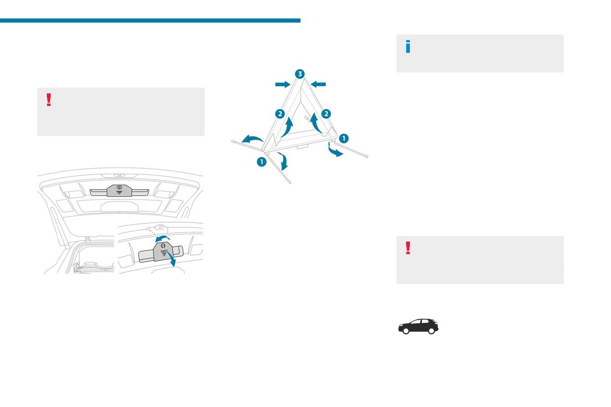
In the event of a breakdown
Warning triangle
Assembling and placing the
For more information on Refuelling and
8
on Misfuel prevention (Diesel), refer to
This reflective and dismantlable device is to be
triangle
the corresponding section.
installed on the side of the road when a vehicle
is broken down or damaged.
1.5 BlueHDi engines
Before getting out of the vehicle
► Switch on the ignition (without starting the
Turn on the hazard warning lamps, then
engine).
put on the safety vest to assemble and install
► Wait around 1 minute and switch off the
the triangle.
ignition.
► Operate the starter motor to start the engine.
If the engine does not start at the first attempt,
Storage compartment
do not keep trying, but restart the procedure.
Tool kit
For versions supplied with a triangle as original
Set of tools supplied with the vehicle.
equipment, refer to the illustration above.
Its content depends on your vehicle's equipment:
For other versions, refer to the assembly
- Temporary puncture repair kit.
instructions provided with the triangle.
- Spare wheel.
► Put the triangle in place behind the vehicle,
as required by local legislation.
These tools are specific to the vehicle
and may vary according to the level of
equipment.
Running out of fuel
Do not use them for any other purpose.
There is a compartment in the interior trim of the
(Diesel)
tailgate to store a warning triangle.
With Diesel engines, the fuel system must be
► After opening the tailgate, release the cover
Accessing the tools
primed if you run out of fuel.
by turning the screw a quarter turn to the left.
Before starting to prime the system, it is
essential to put at least 5 litres of Diesel into the
fuel tank.
207
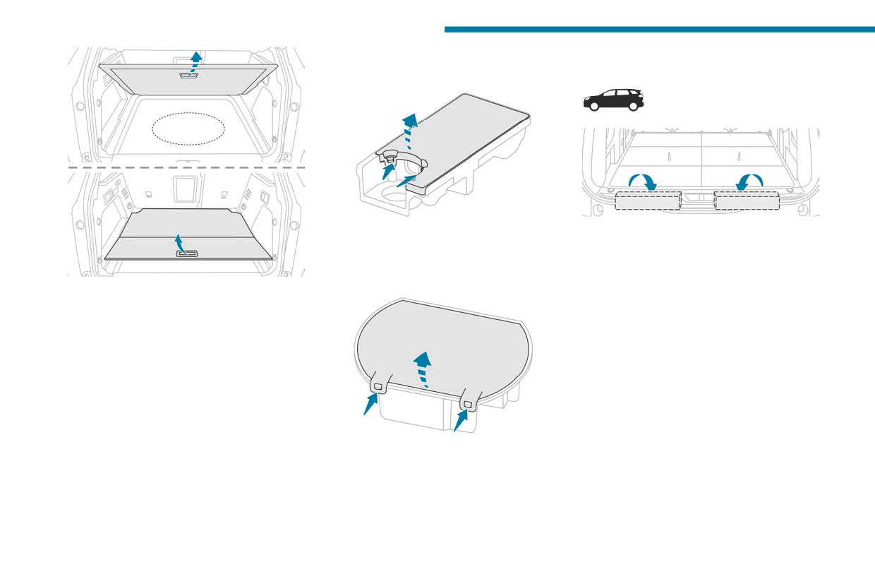
In the event of a breakdown
With temporary puncture repair kit
Accessing the tools
Some of the tools are stored beneath the floor
► Unclip the two fixings to open its cover.
against the boot sill.
The left-hand box contains the wheelbrace and
With spare wheel
its extension piece.
The tool kit is stored in the boot, under the floor.
The right-hand box contains the wheel chocks
To access it:
and the towing eye.
Versions with 2-position boot floor:
To access it:
► Open the boot.
► Open the boot.
► Place the adjustable boot floor in the high
► Fold the concertina panels.
position.
► Install the third row seats.
► Lift the boot floor past the two retractable
► Unclip the required tools from the boot sill
stops.
trim.
► Place the boot floor onto these two stops to
hold it up.
Versions with articulated boot mat
(Rechargeable hybrid):
► Unclip the storage box by pulling it upwards.
► Open the boot.
► Unclip the two fixings to open its cover.
► Unfold the articulated boot mat by pulling its
handle until it is fully opened.
208
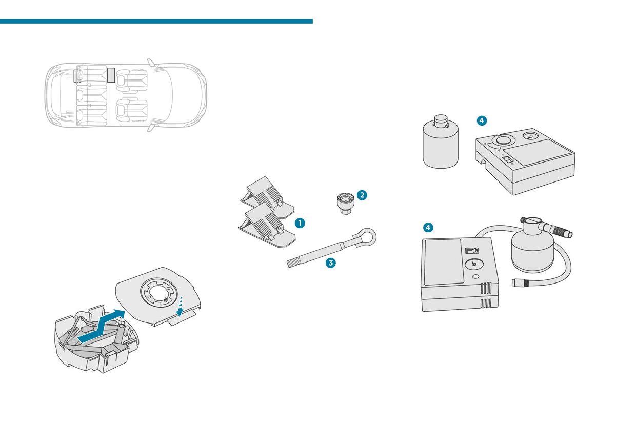
In the event of a breakdown
With temporary puncture repair kit
The tool box is installed at the centre of the
For more information on Towing the vehicle
8
spare wheel beneath the vehicle.
and using the removable towing eye, refer to the
It contains the jack and the wheel bolt cover
corresponding section.
removal tool.
► First, access the spare wheel.
With temporary puncture repair kit
For further information on the Spare wheel,
Kit 1
please refer to the corresponding section.
► Press the tab to unlock the cover.
► While keeping the tab pressed in, slide the
cover to the middle and remove it.
Model without storage box
This kit, stored in a bag, is installed behind the
List of tools
second row left-hand seat.
► Fold the seat backrest onto the cushion to
access the bag.
Model with storage box
Kit 2
This kit is installed in the storage box, located in
front of the second row left-hand seat.
► Open the storage box cover to access the kit.
With spare wheel
1. Chocks to immobilise the vehicle (depending
on equipment)
2. Socket for the wheel security bolts (located in
4.
12 V compressor with cartridge of sealant
the glove box) (depending on equipment)
and speed limit sticker
To adapt the wheelbrace to the special
For temporary repair of a tyre and to adjust
‘security’ bolts.
the tyre pressure.
3. Removable towing eye
209
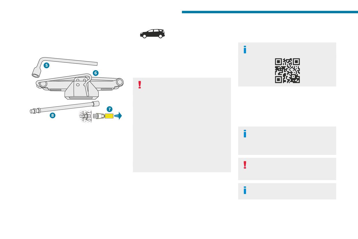
In the event of a breakdown
For more information on the Temporary
8.
Temporary puncture
puncture repair kit, refer to the corresponding
section.
repair kit
With spare wheel
Wheelbrace extension
Visit this link to view explanatory videos:
For loosening/tightening the spare wheel
carrier winch cable nut.
For more information on the Spare wheel, refer
to the corresponding section.
The jack must only be used to change a
wheel with a damaged or punctured tyre.
Made up of a compressor and a sealant
Do not use any jack other than the one
cartridge, it allows you to carry out a temporary
supplied with the vehicle.
repair of the tyre so that you can drive to the
If the vehicle does not have its original jack,
nearest garage.
contact a PEUGEOT dealer or a qualified
It is designed to repair most punctures located
workshop to obtain the one that was intended
on the tyre tread.
by the manufacturer.
5. Wheelbrace
The jack meets European standards,
The vehicle's electric system allows the
For removing the wheel trim and the wheel
as defined in the Machinery Directive
connection of the compressor to the 12 V
bolts.
2006/42/CE, and also complies with UKCA
power supply for long enough to repair a tyre
6. Jack with integrated handle
requirement, as defined by the Supply
after a puncture.
To raise the vehicle.
of Machinery (Safety) Regulations 2008
7. Wheel bolt cap removal tool (depending on
No.1597.
Only the 12 V socket located at the front
equipment)
The jack does not require any maintenance.
of the vehicle can be used to power the
For removing the wheel bolt head finishers on
compressor.
alloy wheels.
For more information on the Tool kit,
refer to the corresponding section.
210
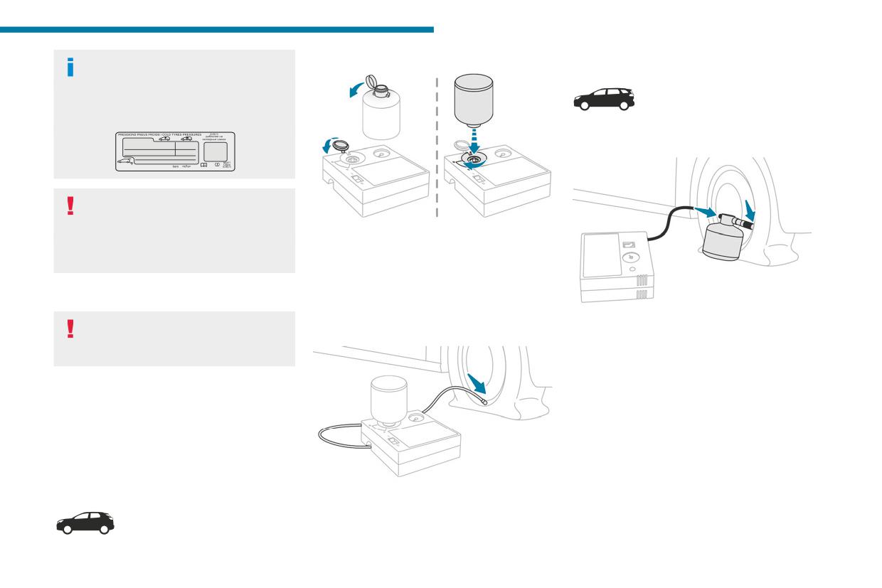
In the event of a breakdown
Tyre inflation pressures are indicated on
Connecting kit 2
8
this label.
For more information on Identification
markings, particularly this label, refer to the
corresponding section.
► Remove the valve cap from the tyre to be
repaired, and place it in a clean place.
Should the pressure of one or more tyres
be adjusted, it is necessary to reinitialise
the under-inflation detection system.
► Remove the transparent cap from the bottle
For more information on Tyre under-inflation
of sealant.
detection, refer to the corresponding section.
► Lift the protective cover before installing the
bottle of sealant on the compressor.
► Turn the bottle of sealant over and screw it a
Repair procedure
quarter turn into the compressor.
► Remove the valve cap from the tyre to be
► Connect the pipe from the bottle of sealant to
Do not remove any foreign body
repaired, and place it in a clean place.
the valve of the tyre to be repaired and tighten
(e.g. nail, screw) which has penetrated
firmly.
the tyre.
► Uncoil the pipe stowed under the compressor.
► Park the vehicle without obstructing traffic
► Connect the pipe from the compressor to the
and apply the parking brake.
bottle of sealant.
► Follow the safety instructions (hazard
Repairing the tyre
warning lamps, warning triangle, high visibility
► Check that the compressor switch is in
jacket, etc.) according to the legislation in force
position "O".
in the country in which you are driving.
► Fully uncoil the electric cable stowed under
► Switch the ignition off.
the compressor.
Connecting kit 1
► Connect the compressor's electric plug to the
► Uncoil the pipe stowed under the compressor.
vehicle's 12 V socket.
► Connect the pipe from the compressor to the
valve of the tyre to be repaired and tighten firmly.
211
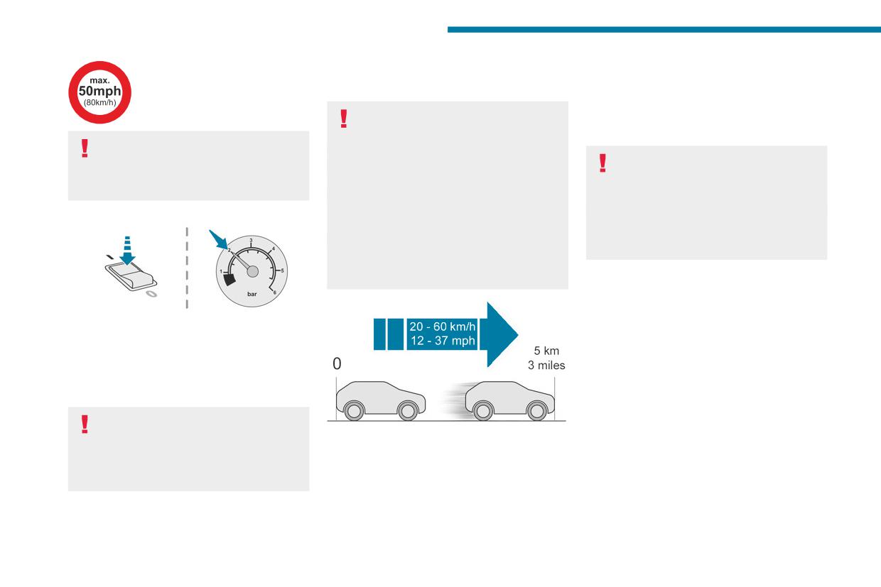
In the event of a breakdown
► Remove the kit.
• If the tyre pressure is correct, drive a second
► Affix the speed limit sticker.
► Refit the cap on the valve.
time for approximately 3 miles (5 kilometres)
► Remove and store the bottle of sealant.
at reduced speed (between 12 and 37 mph
(20 and 60 km/h)), stop then check again
The sealant product is harmful if
the tyre pressure using the kit to confirm the
swallowed and causes irritation to the
effective repair of the tyre.
The speed limit sticker must be affixed
eyes.
inside the vehicle in the area close to the
Keep this product out of the reach of children.
With a tyre repaired using this type of kit,
driver, to remind them that a wheel is in
The use-by date of the fluid is marked on the
do not exceed a speed of 50 mph
temporary use.
bottle.
(80 km/h) and do not drive more than
After use, do not discard the bottle into the
125 miles (200 km).
► Switch the ignition on.
environment; take it to a PEUGEOT dealer or
You must contact a PEUGEOT dealer or a
an authorised waste disposal site.
qualified workshop to have the repair checked
Do not forget to obtain a new bottle of
and the tyre changed.
sealant, available from a PEUGEOT dealer or
a qualified workshop.
Checking/adjusting tyre
pressures
► Switch on the compressor by moving the
The compressor can be used, without injecting
switch to position "I" until the tyre pressure
sealant, to check and, if necessary, adjust the
reaches 2 bar. The sealant product is injected
tyre pressures.
under pressure into the tyre; do not disconnect
► Remove the valve cap from the tyre and keep
the pipe from the valve during this operation (risk
it in a clean place.
of blowback).
► Uncoil the pipe stowed under the compressor.
► Screw the pipe onto the valve and tighten
If after approximately 7 minutes, the
firmly.
pressure of 2 bar is not reached, this
► Drive immediately for approximately 3 miles
► Check that the compressor switch is in
indicates that the tyre is not repairable;
(5 kilometres) at reduced speed (between
position "O".
contact a PEUGEOT dealer or a qualified
12 and 37 mph (20 and 60 km/h)) to plug the
► Fully uncoil the electric cable stowed under
workshop for assistance.
puncture.
the compressor.
► Stop to check the repair and the tyre
► Move the switch to position "O".
► Connect the compressor's electric plug to the
pressure using the kit:
► Disconnect the compressor's electric plug
vehicle's 12 V socket.
• If the tyre pressure is incorrect, contact a
from the vehicle's 12 V socket.
► Switch the ignition on.
PEUGEOT dealer to have the tyre changed.
212
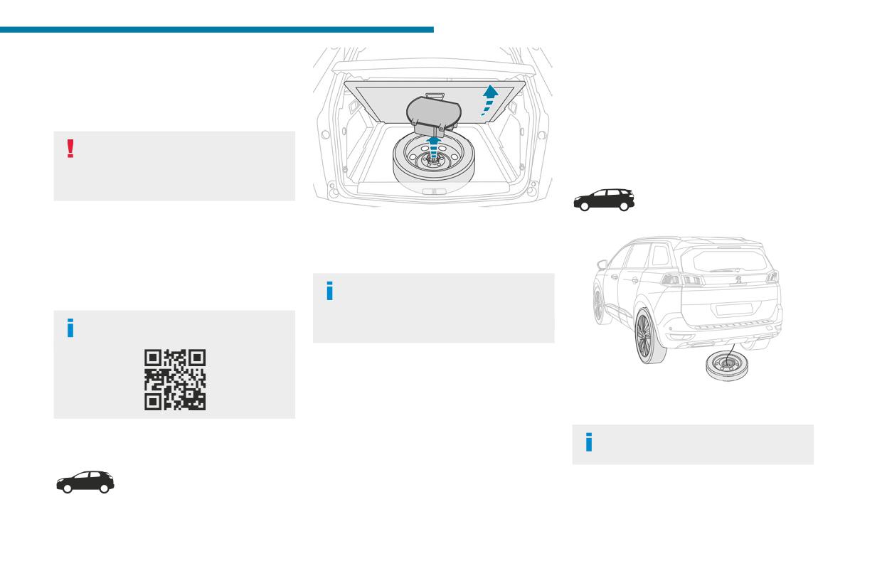
In the event of a breakdown
► Start the compressor by placing the switch at
► Position the fastening device (nut and bolt) in
8
position "I" and adjust the pressure to the value
the middle of the wheel.
shown on the vehicle's tyre pressure label. To
► Tighten the central nut sufficiently to retain
deflate: press the black button located on the
the wheel correctly.
compressor pipe, near the valve connection.
► Put the tool box back in place in the middle of
the wheel and clip it in place.
If after 7 minutes the pressure of 2 bar is
not reached, the tyre is damaged;
Accessing the spare wheel
contact a PEUGEOT dealer or a qualified
workshop for assistance.
► Once the correct pressure is reached, put the
The spare wheel is stored in the boot, under the
switch in position "O".
floor.
► Remove the kit and stow it.
To access the spare wheel, first refer to the Tool
► Refit the cap on the valve.
kit section.
Depending on version, the spare wheel
Spare wheel
may be a standard size steel or alloy
wheel.
Visit this link to view explanatory videos:
In some countries, it is a ‘space saver’ wheel.
Removing the spare wheel
► Slacken the central nut.
► Remove the fastening device (nut and bolt).
The spare wheel is held by a winch system
► Lift the spare wheel towards you from the
underneath the rear of the vehicle.
rear.
Only a "space-saver" type spare wheel
Accessing the spare wheel
► Take the wheel out of the boot.
may be fixed underneath the vehicle.
Putting the spare wheel back in place
► Put the spare wheel back in place in its
housing.
► Slacken the nut on the bolt by a few turns.
213
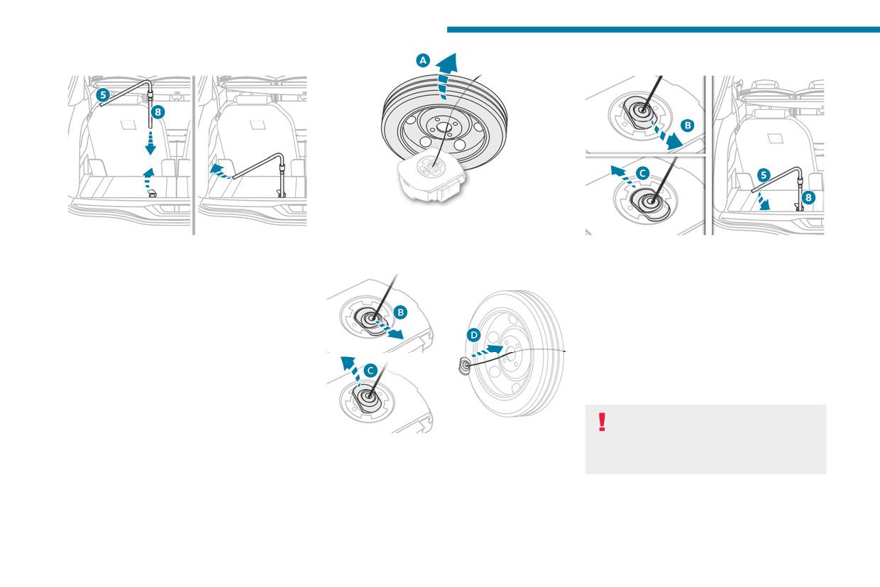
In the event of a breakdown
Removing the spare wheel
Storing the tools
► Remove the wheel/box unit through the rear
of the vehicle.
► Fold up the concertina panel and install
► Straighten the spare wheel to access the tool
► Replace the appropriate tools in the box and
the third row seat, on the left-hand side (if the
box (A).
close the cover.
vehicle is equipped with it).
► Place the tool box on the ground.
► Lift the pre-cut section of carpet to release
► Insert the connecting piece into the tool box
the spare wheel fixing winch nut.
hole (B - C).
► With extension piece 8 placed on the end
► Reel in the winch by loosening the winch
of wheelbrace 5, "tighten" the nut to unreel the
control nut with wheelbrace 5 and extension
winch cable until the spare wheel is flat on the
piece 8: the nut should rotate freely once the
ground. Unwind the length required to access
cable is completely reeled in.
the wheel easily.
► Store the rest of the tools in the storage
areas in the boot sill trim.
The punctured wheel cannot be secured
beneath the vehicle; it must be stored in
► Detach the connecting piece from the cover
the boot (use a cover to protect the inside of
of the tool box (B - C).
the boot).
► Pass the connecting piece through the wheel
hub to release it (D).
214
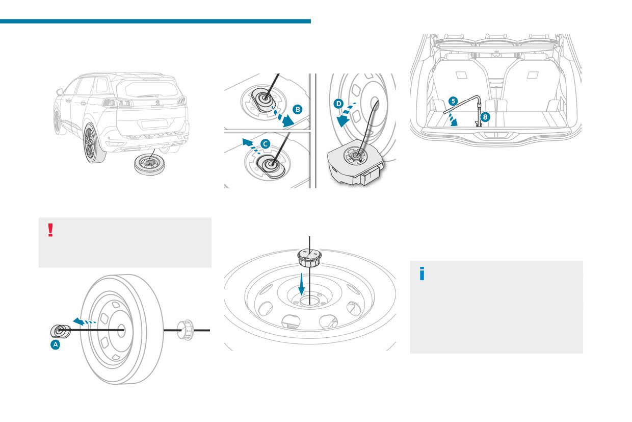
In the event of a breakdown
Putting the winch and spare wheel
► Straighten the wheel.
8
back in place
► Pass the connecting piece through the wheel
hub (A).
► Raise the wheel/box unit underneath the
vehicle, by "loosening" the winch control nut with
wheelbrace 5 and extension piece 8.
► Place the appropriate tools in the box and
► Tighten fully. When the cable is completely
close the cover.
► Insert the connecting piece into the tool box
reeled in, turning the nut no longer encounters
► Place the tool box on the ground.
hole (B - C).
resistance.
► Centre and position the spare wheel on the
► Check that the wheel is properly flattened
When the spare wheel is fitted in place of
tool box (D).
against the floor.
a wheel with a punctured tyre, the winch
and tool box must be placed beneath the
Removing a wheel
vehicle again before restarting.
Wheel with wheel trim
When removing the wheel, first remove
the wheel trim by pulling with both hands on
one of the upper arms.
When refitting the wheel, refit the wheel
trim, starting by placing its aperture in line
with the valve and then pushing it into place
all round its edge with the palm of your hand.
► Insert the centring guide into the wheel hub.
► Place the wheel/box unit beneath the rear of
the vehicle.
215
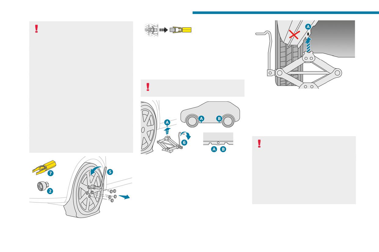
In the event of a breakdown
Parking the vehicle
Immobilise the vehicle where it does
not obstruct traffic: the ground must be level,
► To remove the wheel bolt cover on each of
stable and non-slippery.
the bolts, use tool 7 (alloy wheels).
With a manual gearbox, engage first gear
► Fit security socket 2 on wheelbrace 5 to
to lock the wheels, apply the parking brake,
slacken the security bolt.
unless it is set to automatic mode, and switch
► Slacken the other bolts using the
off the ignition.
wheelbrace 5 only.
With an automatic gearbox, select mode P
to lock the wheels, apply the parking brake,
Never use an impact wrench on the
unless it is set to automatic mode, and switch
security bolt socket.
► Extend jack 6 until its head comes into
off the ignition.
contact with jacking point A or B; contact area A
Check that the parking brake indicator lamps
or B on the vehicle must be properly inserted
on the instrument panel are on fixed.
into the central part of the head of the jack.
The occupants must get out of the vehicle
► Raise the vehicle until there is sufficient
and wait where they are safe.
space between the wheel and the ground to
If necessary, place a chock under the wheel
easily admit the spare (not punctured) wheel.
diagonally opposite the wheel to be changed.
Never go underneath a vehicle raised using a
Ensure that the jack is stable. If the
jack; use an axle stand.
ground is slippery or loose, the jack may
slip or collapse - risk of injury!
► Place the foot of jack 6 on the ground and
Take care to position the jack strictly at
ensure that it is directly below the front A or
one of the jacking points A or B under the
rear B jacking point on the underbody, whichever
vehicle, ensuring that the head of the jack is
is closest to the wheel to be changed.
centred under the contact area on the vehicle.
Otherwise, there is a risk of damage to the
vehicle and/or of the jack collapsing - risk of
injury!
216
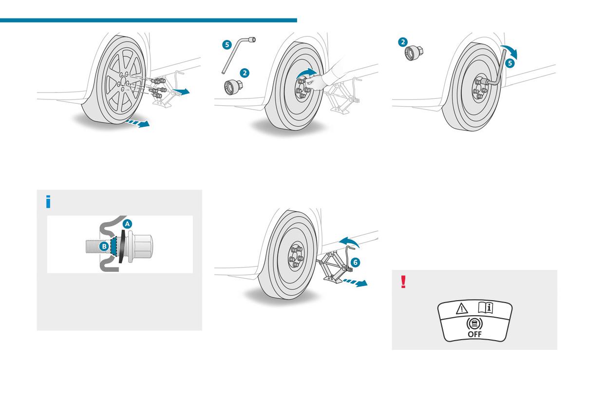
In the event of a breakdown
8
► Remove the bolts and store them in a clean
► Tighten the security bolt using the
place.
► Fit the wheel on the hub.
wheelbrace 5 equipped with a security socket 2.
► Remove the wheel.
► Screw in the bolts by hand as far as possible.
► Tighten the other bolts using the
► Pre-tighten the security bolt using the
wheelbrace 5 only.
Fitting a wheel
wheelbrace 5 equipped with a security socket 2.
► Refit the bolt covers to each of the bolts
► Pre-tighten the other bolts using the
(depending on equipment).
Fitting a steel or "space-saver" type
wheelbrace 5 only.
► Store the tools.
spare wheel
After changing a wheel
Store the punctured wheel in the boot or,
depending on version, remove the central cover
first to store it beneath the floor in place of the
spare wheel.
If the vehicle is fitted with alloy wheels, the
With a non-standard or 'space-saver'
washers A do not make contact with the steel
spare wheel
or "space-saver" type spare wheel. The wheel
is held in place by the conical contact surface
► Lower the vehicle again fully.
B of each bolt.
► Fold jack 6 and remove it.
217
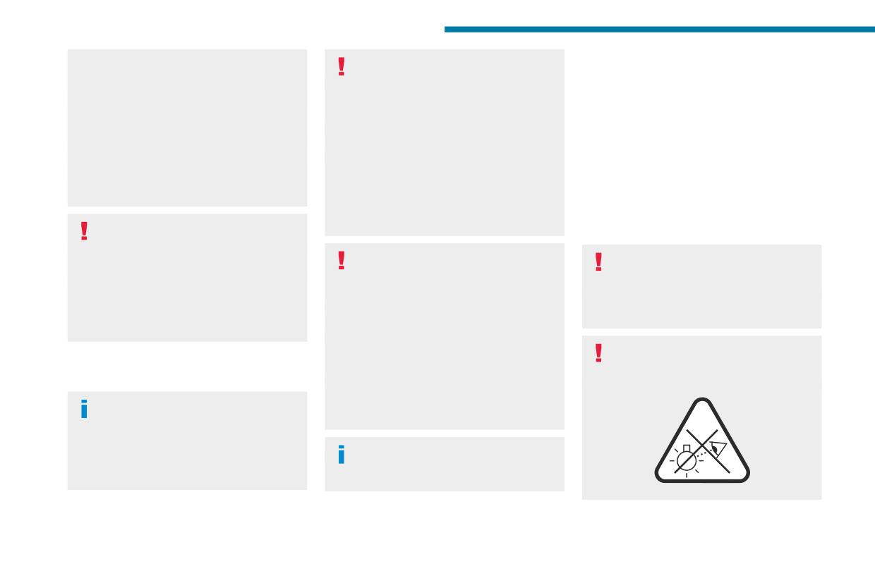
In the event of a breakdown
Deactivate certain driving aid functions
The headlamps have polycarbonate
Light-emitting diode (LED)
(Active Safety Brake, Adaptive cruise control,
lenses with a protective coating:
headlamps and lamps
etc.).
- Do not clean them with a dry or abrasive
Do not exceed the maximum authorised
cloth, nor with detergent or solvent
Depending on version, the affected types of
speed of 50 mph (80 km/h) or the maximum
products.
headlamps/lamps are:
distance of 50 miles (80 km).
- Use a sponge and soapy water or a pH
- LED technology headlamps.
Driving with more than one spare wheel of
neutral product.
- Full LED technology headlamps.
this type is prohibited.
- When using a high-pressure washer on
- Direction indicator side repeaters.
The wheel trim from the replaced wheel must
persistent marks, do not keep the lance
- Side spotlamps.
not be refitted.
directed towards the headlamps, lamps or
- Brake lamps.
their edges for too long, so as not to damage
- LED technology rear lamps.
their protective coating and seals.
- Third brake lamp.
Go to a PEUGEOT dealer or a qualified
- Number plate lamps.
workshop.
Have the tightening of the spare wheel's bolts
Changing a bulb must only be done with
If you need to replace this type of bulb,
and its tyre pressure checked.
the ignition off and after the headlamp /
you must contact a PEUGEOT dealer or
Have the punctured tyre examined. After
lamp has been switched off for several
a qualified workshop.
inspection, the technician will advise you on
minutes - risk of serious burns!
Do not touch the LED or Full LED technology
whether the tyre can be repaired or if it must
Do not touch the bulb directly with your
headlamps - risk of electrocution!
be replaced.
fingers; use a lint-free cloth.
It is essential only to use anti-ultraviolet
Never look too closely at the light beam
(UV) type bulbs, so as not to damage the
of LED technology lamps - risk of serious
Changing a bulb
headlamp.
eye injury!
Always replace a failed bulb with a new bulb
In some weather conditions (e.g. low
of the same type and specification. To avoid
temperature or humidity), misting on the
lighting imbalance, replace the bulbs in pairs.
internal surface of the glass of the headlamps
and rear lamps is normal, and will disappear
Refitting the lamp units
after the lamps have been on for a few
Perform the operations in the reverse
minutes.
order to dismantling.
218
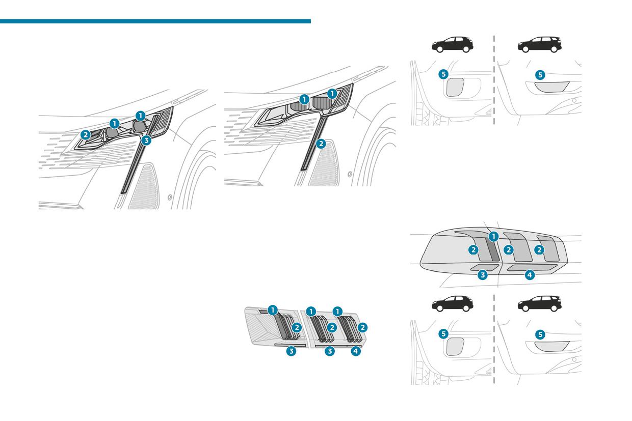
In the event of a breakdown
Front lamps
Model with
8
LED technology headlamps
Model with Full
LED technology headlamps
1. Daytime running lamps/Sidelamps/Brake
lamps (LED)
2. Daytime running lamps/Sidelamps (LED)
3. Direction indicators (LED)
4. Reversing lamps (LED)
5. Foglamps (P21W)
1. Dipped beam headlamps/Main beam
headlamps
Model with LED technology lamps
1. Dipped beam headlamps/Main beam
2. Daytime running lamps/Sidelamps /Direction
headlamps
indicators
2. Static cornering lamps
3. Daytime running lamps/Sidelamps /Direction
Rear lamps
indicators
Model with Full LED technology
lamps
219
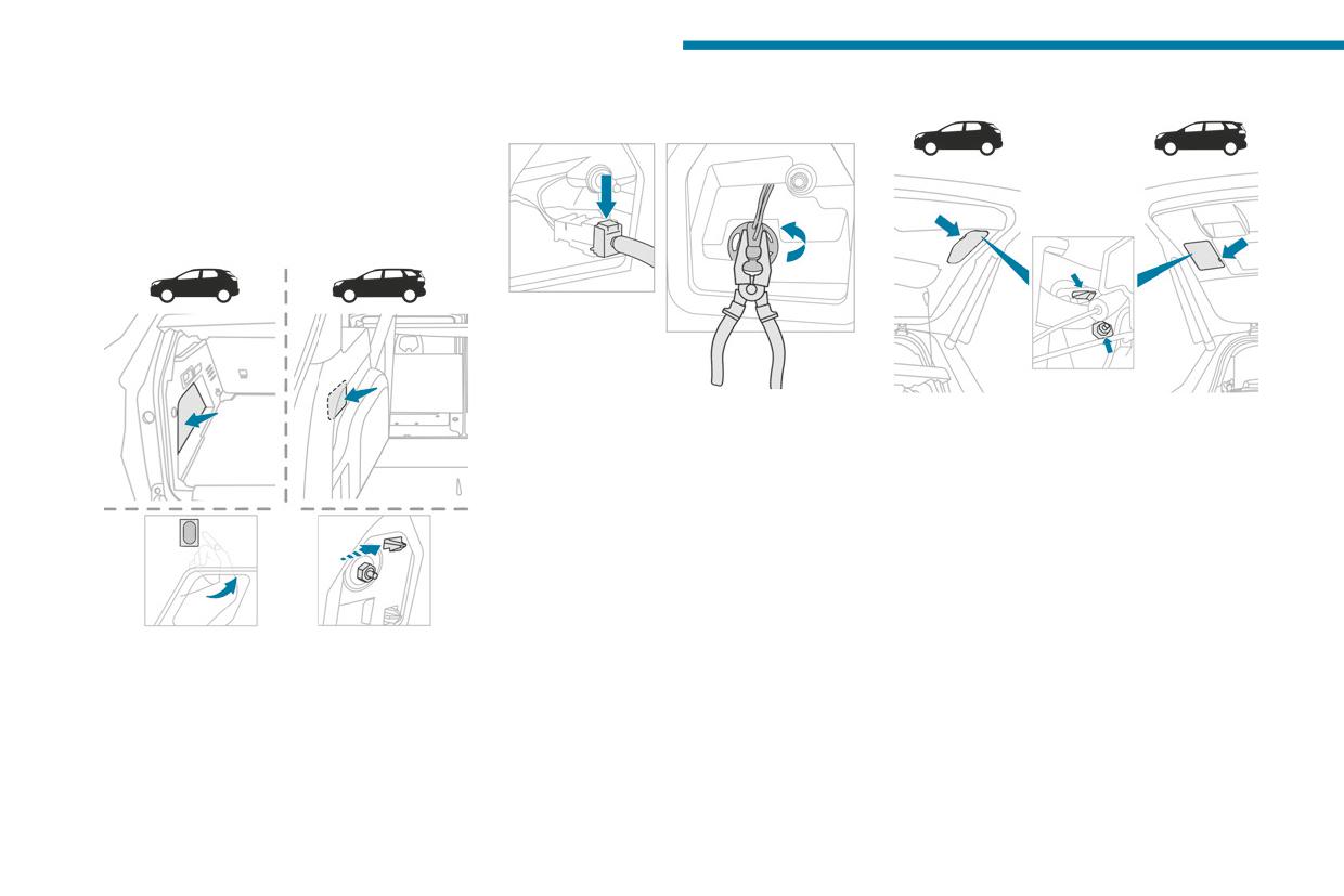
In the event of a breakdown
► Disengage the retaining clip, while slightly
Reversing lamps (on the tailgate)
1. Brake lamps (LED)
pushing the lamp back.
2. Sidelamps/daytime running lamps (LED)
3. Direction indicators (WY16W amber)
4. Reversing lamps (W16W)
5. Foglamps (P21W)
Direction indicators (on the wings)
► From the outside, carefully remove the lamp
► Open the tailgate, then insert a flat
by pulling it to the rear, then up.
screwdriver into the cut-out to unclip the access
► Disconnect the lamp connector.
cover on the side in question.
► Turn the bulb holder a quarter turn using a
► Unblock the lamp fixing nut with a 10 mm box
universal pair of pliers, if necessary, and pull it
spanner.
out.
► Manually unscrew and remove the lamp
► Remove the bulb and replace it.
fixing nut.
► Disengage the retaining clip, while slightly
pushing the lamp back.
► Open the tailgate, then unclip the access
cover on the side in question.
► Unblock the lamp fixing nut with a 10 mm box
spanner.
► To avoid losing the nut in the wing trim if it
drops, first place a cloth below it.
► Manually unscrew and remove the lamp
fixing nut.
220
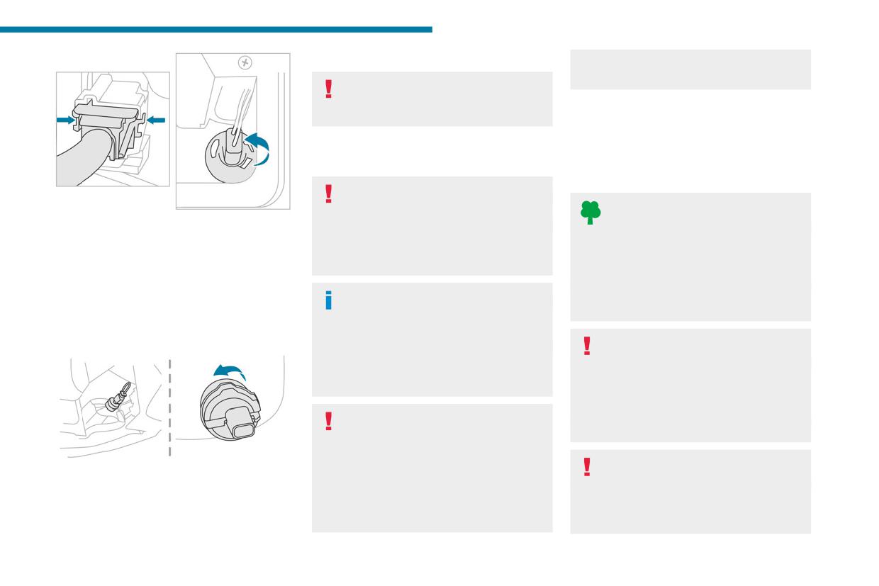
In the event of a breakdown
► Turn the bulb a quarter turn and replace it.
additional equipment connected exceeds 10
8
milliamperes.
When changing the bulb within a few
minutes of switching off the ignition, take
care not to touch the exhaust - risk of burns!
12 V battery/Accessory
batteries
Fuses
Lead-acid starter batteries
Changing a fuse
All work must be carried out only by a
These batteries contain harmful
PEUGEOT dealer or a qualified workshop
substances (sulphuric acid and lead).
► From the outside, carefully remove the lamp
The replacement of a fuse by a third party
They must be disposed of in accordance
by pulling it to the rear.
could cause a serious malfunction of the
with regulations and must never under any
► Disconnect the lamp connector by pressing
vehicle.
circumstances be discarded with household
on each side.
waste.
► Turn the bulb holder a quarter turn and
Installing electrical accessories
Dispose of used batteries at a designated
remove it.
The vehicle's electrical system is
collection point.
► Remove the bulb and replace it.
designed to operate with standard or optional
Foglamps (P21W)
equipment.
Protect your eyes and face before
Before fitting other electrical equipment
handling the battery.
or accessories to your vehicle, contact a
All operations on the battery must be carried
PEUGEOT dealer or a qualified workshop.
out in a well ventilated area and away from
naked flames and sources of sparks, to avoid
PEUGEOT accepts no responsibility for
any risk of explosion or fire.
the cost incurred in repairing the vehicle
Wash your hands afterwards.
or for rectifying malfunctions resulting from
the installation of accessories not supplied or
Electronic control units/LED
These bulbs are replaced from outside the rear
not recommended by PEUGEOT and not
technology headlamps
bumper.
installed in accordance with its
Never connect the negative jump lead to the
► Pass your hand under the bumper.
recommendations, in particular when the
metal part of the electronic control units or at
► Turn the bulb holder a quarter turn and
combined power consumption of all of the
the back of the headlamps.
remove it.
221
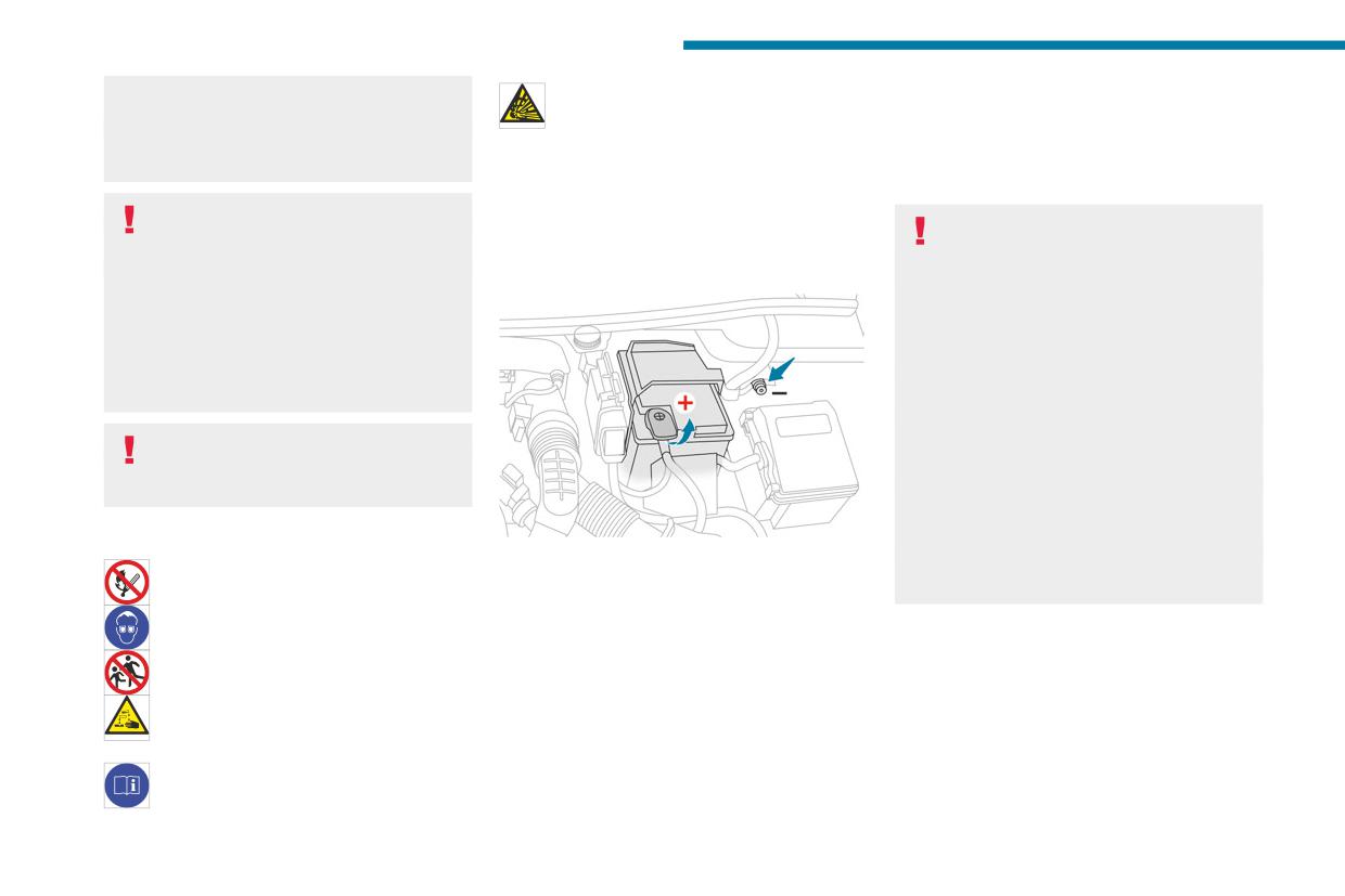
In the event of a breakdown
Risk of destroying the electronic control
Explosive gases can be present close to
Starting using another battery
units and/or headlamps!
the battery.
If the vehicle's battery is flat, the engine can be
Connect to the remote earth point provided
started using a backup battery (either external or
for this purpose.
With petrol/Diesel engines
from another vehicle) and jump leads or using a
Procedure for starting the engine using another
battery booster.
Frozen battery
battery or for charging a discharged battery.
Never start the engine by connecting a
Never try to charge a frozen battery - risk
Accessing the battery
battery charger.
of explosion!
Never use a 24 V or higher battery booster.
If the battery has frozen, have it checked by a
The battery is located under the bonnet.
Check beforehand that the backup battery
PEUGEOT dealer or by a qualified workshop,
has a nominal voltage of 12 V and a capacity
who will verify that the internal components
at least equal to that of the discharged
have not been damaged and that the case
battery.
has not cracked, which could lead to a risk of
The two vehicles must not be in contact with
leakage of toxic and corrosive acid.
each other.
Switch off all electricity-consuming equipment
Automatic gearbox
on both vehicles (audio system, wipers,
Never try to start the engine by pushing
lighting, etc.).
the vehicle.
Make sure that the jump leads are well away
from the engine’s moving parts (fan, belt,
Symbols
etc.).
For access to the (+) terminal:
Do not disconnect the (+) terminal while the
No sparks or naked flames, no smoking.
► Release the bonnet by pulling the internal
engine is running.
release lever, then the external safety catch.
Always protect your eyes. Explosive
► Raise the bonnet.
gases can cause blindness and injury.
(+) Positive terminal with a quick-release
Keep the vehicle's battery out of the reach
terminal.
of children.
(-) Negative terminal.
The vehicle's battery contains sulphuric
As the battery's negative terminal is not
acid which can make you go blind or
accessible, a remote earth point is located near
cause severe burns.
the battery.
For more information, refer to the
handbook.
222
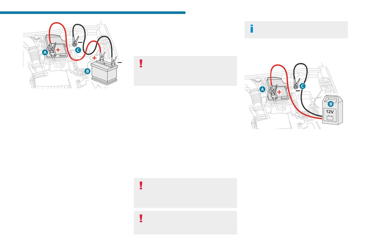
In the event of a breakdown
► Refit the plastic cover to the (+) terminal, if
It is not necessary to disconnect the
8
the vehicle has one.
battery.
► Allow the engine to run for at least
► Switch the ignition off.
30 minutes, with the vehicle stationary, so that
► Switch off all electrical consumers (audio
the battery reaches an adequate state of charge.
system, lighting, wipers, etc.).
Driving immediately without having
reached a sufficient level of charge may
affect some of the vehicle's functions (e.g.
Stop & Start).
► Lift the plastic cover on the (+) terminal, if the
Charging the battery using a battery
vehicle has one.
charger
► Connect the red cable to the (+) terminal of
For optimum service life of the battery, it is
flat battery A (at the metal elbow), then to the
essential to maintain an adequate state of
(+) terminal of the backup battery B or of the
charge.
booster.
In some circumstances, it may be necessary to
► Connect one end of the green or black cable
charge the battery:
► Switch off charger B before connecting
to the (-) terminal of the backup battery B or of
- When using the vehicle mainly for short
the cables to the battery, so as to avoid any
the booster (or to an earth point on the assisting
journeys.
dangerous sparks.
vehicle).
- If the vehicle is to be taken off the road for
► Ensure that the charger cables are in good
► Connect the other end of the green or black
several weeks.
condition.
cable to the earth point C.
Consult a PEUGEOT dealer or a qualified
► Lift the plastic cover on the (+) terminal, if the
► Start the engine on the assisting vehicle and
workshop.
vehicle has one.
leave it running for a few minutes.
► Connect the cables of charger B as follows:
► Operate the starter on the broken down
To charge the vehicle's battery yourself,
• the positive (+) red cable to the (+) terminal
vehicle and let the engine run.
use only a charger compatible with
of battery A,
If the engine does not start immediately, switch
lead-acid batteries with a nominal voltage of
• the negative (-) black cable to earth point C
off the ignition and wait a few moments before
12 V.
on the vehicle.
trying again.
► At the end of the charging operation, switch
► Wait for it to return to idle.
Follow the instructions provided by the
off charger B before disconnecting the cables
► Disconnect the jump leads in reverse order.
manufacturer of the charger.
from battery A.
Never reverse polarities.
223
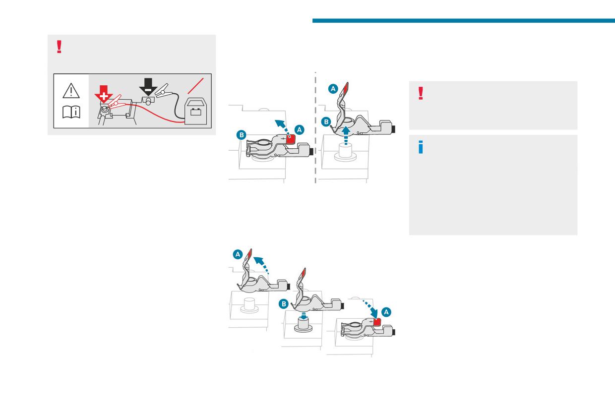
In the event of a breakdown
If this label is present, use only a 12 V
Quick-release terminal clamp
► Push clamp B fully down.
charger to avoid causing irreversible
► Lower lever A to lock clamp B.
damage to the electrical components.
Disconnecting the (+) terminal
► Depending on equipment, lower the plastic
cover on the (+) terminal.
24V
Do not force the lever when pressing on
it, as if the clamp is not positioned
correctly, locking will then not be possible.
12V
Start the procedure again.
The Stop & Start system may not be
Disconnecting/Reconnecting the 12 V
operational during the trip following the
battery
first engine start.
In this case, the system will only be available
In order to maintain an adequate state of
again after a continuous period with the
charge for starting the engine, we recommend
► Depending on equipment, lift the plastic cover
vehicle immobilised, the duration of which
disconnecting the battery if the vehicle is to be
on the (+) terminal.
depends on the exterior temperature and the
unused for an extended period.
► Raise lever A fully to release clamp B.
state of charge of the battery (up to about 8
Before disconnecting the 12 V battery:
► Remove clamp B by lifting it off.
hours).
► Close all openings (doors, boot, windows,
Reconnecting the (+) terminal
roof).
► Switch off all electricity-consuming devices
With hybrid engines
(audio system, wipers, lamps, etc.).
Procedure for starting the engine using another
► Switch off the ignition and wait for 4 minutes.
battery or for charging a discharged battery
After accessing the 12 V battery, it is only
(12 V or 48 V).
necessary to disconnect the (+) terminal.
► Access to the 12 V battery.
For more information on Accessing the battery,
refer to the corresponding section.
► If necessary, perform the 12 V battery
disconnection/reconnection procedure.
For more information on Disconnecting/
Reconnecting the battery, refer to the
► Raise lever A fully.
corresponding section.
► Refit open clamp B on the (+) terminal.
224
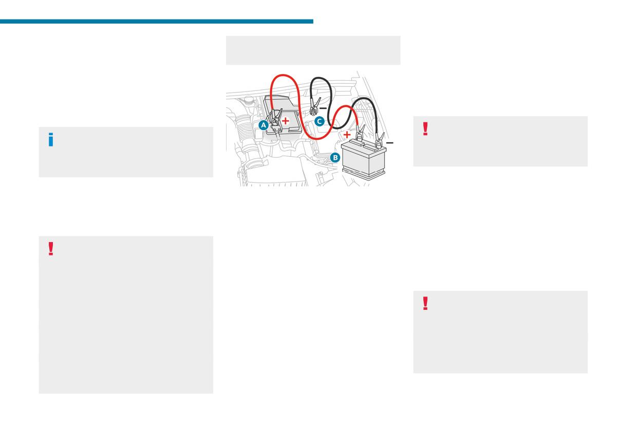
In the event of a breakdown
► After reconnecting the 12 V battery, perform
Do not disconnect the (+) terminal while the
► Wait for it to return to idle.
8
the automatic reset procedures of the electronic
engine is running.
► Disconnect the jump leads in reverse order.
systems and manual reset of some equipment.
► Refit the plastic cover to the (+) terminal, if
For more information on Following
the vehicle has one.
reconnection, refer to the corresponding
► Allow the engine to run for at least
section.
30 minutes, with the vehicle stationary, so that
the battery reaches an adequate state of charge.
Starting using another battery
Driving immediately without having
The hybrid system starts the vehicle, but
reached a sufficient level of charge may
a 12 V supply is required. There are
affect some of the vehicle's functions (e.g.
several reasons why the vehicle cannot be
e-Auto mode).
started.
If the 12 V battery is flat, the 12 V power supply
Charging the 12 V battery using a
can be ensured using a backup battery (either
► Lift the plastic cover on the (+) terminal, if the
battery charger
external or from another vehicle) and jump leads
vehicle has one.
For optimum service life of the battery, it is
or using a battery booster or using a battery
► Connect the red cable to the (+) terminal of
essential to maintain an adequate state of
charger.
flat battery A (at the metal elbow), then to the
charge.
(+) terminal of the backup battery B or of the
In some circumstances, it may be necessary to
Never use a 24 V or higher battery
booster.
charge the battery (e.g. if the vehicle is to be
booster.
► Connect one end of the green or black cable
taken off the road for several weeks)
Check beforehand that the backup battery
to the (-) terminal of the backup battery B or of
Consult a PEUGEOT dealer or a qualified
has a nominal voltage of 12 V and a capacity
the booster (or to an earth point on the assisting
workshop.
at least equal to that of the discharged
vehicle).
battery.
The hybrid system is connected to the
► Connect the other end of the green or black
The two vehicles must not be in contact with
12 V network through the DC/DC
cable to the earth point C.
each other.
converter. Any operation may affect the
► Start the engine on the assisting vehicle and
Switch off all electricity-consuming equipment
overall behaviour of the system.
leave it running for a few minutes.
on both vehicles (audio system, wipers,
To charge the vehicle's battery yourself, use
► Operate the starter on the broken down
lighting, etc.).
only a charger compatible with lead-acid
vehicle and let the engine run.
Make sure that the jump leads are well away
batteries with a nominal voltage of 12 V.
If the engine does not start immediately, switch
from the engine’s moving parts (fan, belt,
off the ignition and wait a few moments before
etc.).
trying again.
225
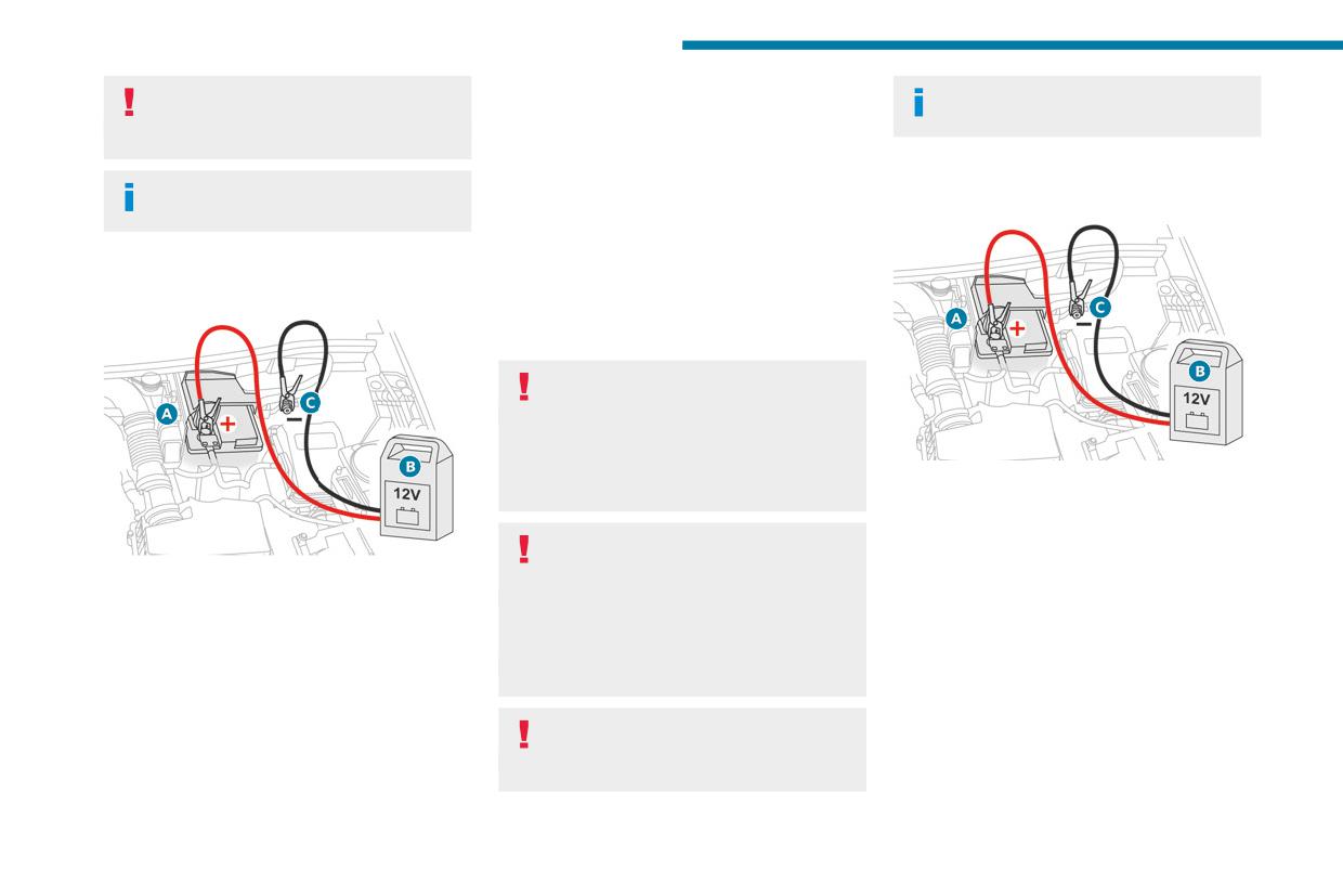
In the event of a breakdown
Follow the instructions provided by the
► At the end of the charging operation, switch
It is not necessary to disconnect the
manufacturer of the charger.
off charger B before disconnecting the cables
battery.
Never reverse polarities.
from battery A.
► Switch the ignition off.
Charging the 48 V battery using a
► Switch off all electrical consumers (audio
It is not necessary to disconnect the
12 V battery charger
system, lighting, wipers, etc.).
battery.
If the start fails, refer to the paragraph "Starting
► Switch the ignition off.
using another battery" and follow the
► Switch off all electrical consumers (audio
recommended procedure.
system, lighting, wipers, etc.).
In case of failure, especially after long storage,
the 48 V battery may be discharged and require
a charging process.
Do not try to charge the hybrid system
directly.
The hybrid system is connected to the 12 V
network through the DC/DC converter. Any
operation may affect the overall behaviour of
► Switch off charger B before connecting the
the system.
cables to the 12 V battery, so as to avoid any
dangerous sparks.
Only use a specific 12 V battery charger
► Ensure that the charger cables are in good
capable of maintaining 13.5 V with a high
► Switch off charger B before connecting
condition.
level of current 40-50 A (approx. 600 W).
the cables to the battery, so as to avoid any
► Lift the plastic cover on the (+) terminal, if the
To charge the vehicle's battery yourself, use
dangerous sparks.
vehicle has one.
only a charger compatible with lead-acid
► Ensure that the charger cables are in good
► Connect the cables of charger B as follows:
batteries with a nominal voltage of 12 V.
condition.
• the positive (+) red cable to the (+) terminal
Never use a 24 V or higher battery booster.
► Lift the plastic cover on the (+) terminal, if the
of battery A,
vehicle has one.
• the negative (-) black cable to earth point C
Follow the instructions provided by the
on the vehicle.
► Connect the cables of charger B as follows:
manufacturer of the charger.
► Open the driver's door and turn the ignition
• the positive (+) red cable to the (+) terminal
Never reverse polarities.
on without pressing the brake pedal (to wake
of battery A.
• the negative (-) black cable to earth point C
up the vehicle).
on the vehicle.
226
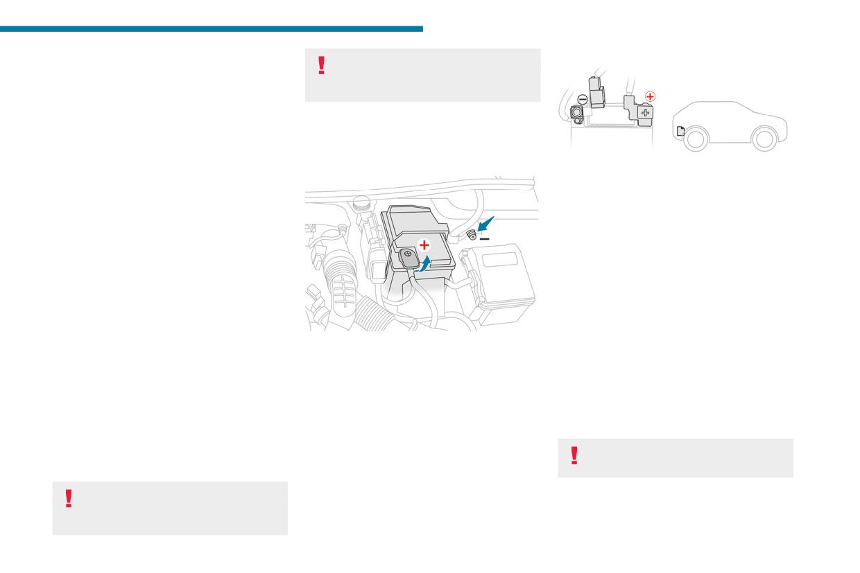
In the event of a breakdown
The hybrid system will automatically start
Jump-starting another vehicle
8
charging the 48 V battery after 1 minute with
Do not start or jump-start another vehicle
a 12 V power supply higher than 13.5 V. The
using the vehicle’s accessory batteries.
current supplied by the battery charger should be
about 30-50A.
Accessing the accessory batteries
When the appropriate energy level is reached
in the 48 V battery (between 30 to 40 minutes
Front
depending on 12 V battery state of charge), the
The front battery is located under the bonnet.
► Lift the boot floor.
hybrid system automatically stops the charging
(+) Positive terminal, protected by a red plastic
process of the 48 V battery.
cover (not accessible).
► At the end of the charging operation, switch
(-) Negative terminal with a black quick-release
off charger B before disconnecting the cables
connector.
from 12 V battery A.
► Refit the plastic cover to the (+) terminal, if
Charging the front battery using a
the vehicle has one.
battery charger
► Operate the starter on the vehicle and let the
For optimum service life of the front battery, it
engine run.
is essential to maintain an adequate state of
► Wait for it to return to idle.
charge.
► Allow the engine to run for at least
In some circumstances, it may be necessary to
20 minutes, with the vehicle stationary (in a
For access to the (+) terminal:
charge the front battery:
ventilated area to avoid accumulation of exhaust
► Release the bonnet by pulling the internal
- When using the vehicle mainly for short
gases), so that the 48 V battery reaches an
release lever, then the external safety catch.
journeys.
adequate state of charge.
► Raise the bonnet.
- If the vehicle is to be taken off the road for
(+) Positive terminal with a quick-release
several weeks.
With rechargeable hybrid
terminal.
Consult a PEUGEOT dealer or a qualified
engines
(-) Negative terminal.
workshop.
The rechargeable hybrid system has two
As the battery's negative terminal is not
To charge the vehicle's front battery
accessory batteries: one at the front and one at
accessible, a remote earth point is located near
yourself, use only a charger compatible
the rear of the vehicle.
the battery.
Replacing the accessory batteries
Rear
Contact a PEUGEOT dealer or a
The rear battery is located in the boot.
qualified workshop.
To reach the battery:
227
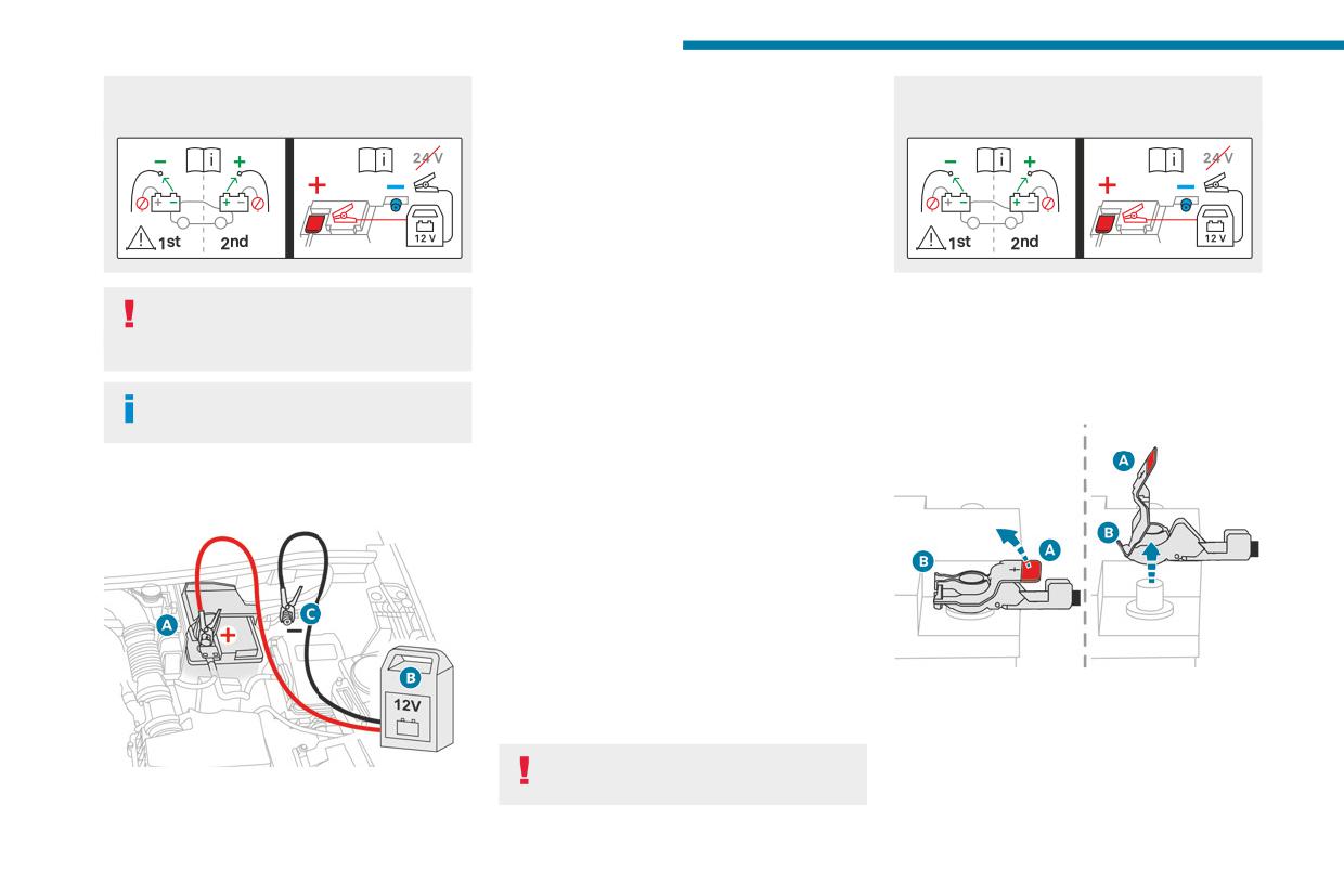
In the event of a breakdown
with lead-acid batteries with a nominal voltage
► Switch off charger B before connecting
accessory batteries - risk of irreversible
of 12 V.
the cables to the battery, so as to avoid any
damage!
dangerous sparks.
► Ensure that the charger cables are in good
condition.
► Lift the plastic cover on the (+) terminal, if the
vehicle has one.
► Connect the cables of charger B as follows:
• Positive (+) red cable to the (+) terminal on
battery A.
Follow the instructions provided by the
Disconnection
• Negative (-) black cable to earth point C on
manufacturer of the charger.
the vehicle.
Rear battery:
Never reverse polarities.
► At the end of the charging operation, switch
► Disconnect the (-) terminal using the black
off charger B before disconnecting the cables
quick-release connector.
It is not necessary to disconnect the
from battery A.
Front battery:
battery.
Disconnecting/reconnecting the
► Switch the ignition off.
accessory batteries
► Switch off all electrical consumers (audio
system, lighting, wipers, etc.).
Procedure for disconnecting/reconnecting the
accessory batteries in the event of long-term
immobilisation of the vehicle.
Before disconnecting the accessory batteries:
► Open the driver's door and boot.
► Close all other doors.
► Switch off all electrical consumers (audio
system, wipers, lamps, etc.).
► Switch off the ignition and wait for the
► Disconnect the (+) terminal by disconnecting
READY indicator lamp to go out.
the red quick-release clamp:
► Observe a waiting time of 4 minutes.
• Raise lever A fully to release clamp B.
• Remove clamp B by lifting it off.
Never reverse the order of the steps for
disconnecting and reconnecting the
Reconnection
Front battery:
228
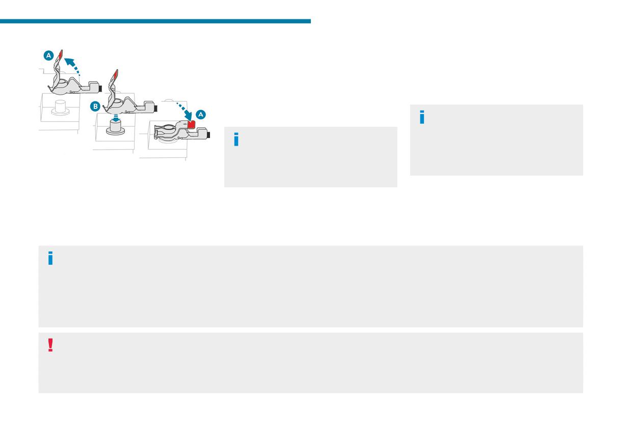
In the event of a breakdown
► Connect the (-) terminal using the black
– Remote control key or electronic key
8
quick-release connector.
(depending on version).
- Sunroof and electric blind.
Following reconnection
- Electric windows.
After reconnecting the battery, turn on the
- Date and time.
ignition and wait 1 minute before starting the
- Preset radio stations.
engine, to enable the electronic systems to
After reconnecting the battery, the
initialise.
message "Collision risk detection
For right-hand drive versions, when the
system fault" is displayed on the instrument
total distance recorder has reached
panel when the ignition is switched on. This
62 miles (100 km), you must wait
operation is perfectly normal. The message
approximately 15 minutes before starting the
will disappear while driving.
► Connect the (+) terminal by connecting the
red quick-release clamp:
engine.
• Raise lever A fully.
If minor problems nevertheless persist following
• Refit open clamp B on the (+) terminal.
Towing the vehicle
this operation, contact a PEUGEOT dealer or a
• Push clamp B fully down.
qualified workshop.
Procedure for having your vehicle towed or
• Lower lever A to lock clamp B.
Referring to the relevant section, reinitialise
for towing another vehicle using a removable
Rear battery:
certain equipment:
mechanical device.
General recommendations
Observe the legislation in force in the country where you are driving.
Check that the towing vehicle is heavier than the towed vehicle.
The driver must remain at the wheel of the towed vehicle and must have a valid driving licence.
When towing a vehicle with all four wheels on the ground, always use an approved towbar; ropes and straps are prohibited.
The towing vehicle must move off gently.
When the vehicle is towed with its engine off, there is no longer braking and steering assistance.
A professional recovery service must be called in the following cases:
- broken down on a motorway or main road;
- not possible to put the gearbox into neutral, unlock the steering, or release the parking brake;
- not possible to tow a vehicle with an automatic gearbox, with the engine running;
- towing with only two wheels on the ground;
229
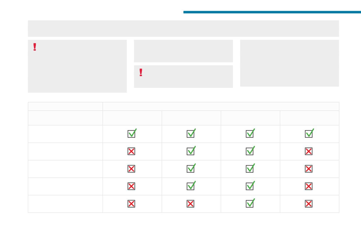
In the event of a breakdown
- four-wheel drive vehicle;
- no approved towbar available.
Special feature of towing for hybrid
(100 metres) at a maximum speed of 6 mph
N, then switch off the hybrid system (READY
vehicles
(10 km/h) (automatic gearbox in mode N and
indicator lamp off).
With both rear wheels on the ground: it
N displayed in the instrument panel).
Always call on professionals for recovery of
is only authorized for short distances (about
the vehicle on a flatbed lorry or trailer.
9 miles (15 km)) and at reduced speed
Rechargeable hybrid vehicles
Use the towing eye only to free the vehicle
(maximum 15 mph (25 km/h)).
Before any intervention, with the ignition
if it is stuck, or to secure it for recovery on a
With all four wheels on the ground: the
on, depress the brake pedal and select mode
flatbed lorry or trailer.
vehicle can be towed a maximum of 0.06 mile
Towing constraints
Type of vehicle
Front wheels on the
Rear wheels on the
Flatbed
4 wheels on the ground
(engine/gearbox)
ground
ground
with towbar
Internal combustion/Manual
Internal combustion/Automatic
Hybrid/Automatic
Rechargeable hybrid 2WD
Rechargeable hybrid 4WD
2WD: 2-wheel drive.
230
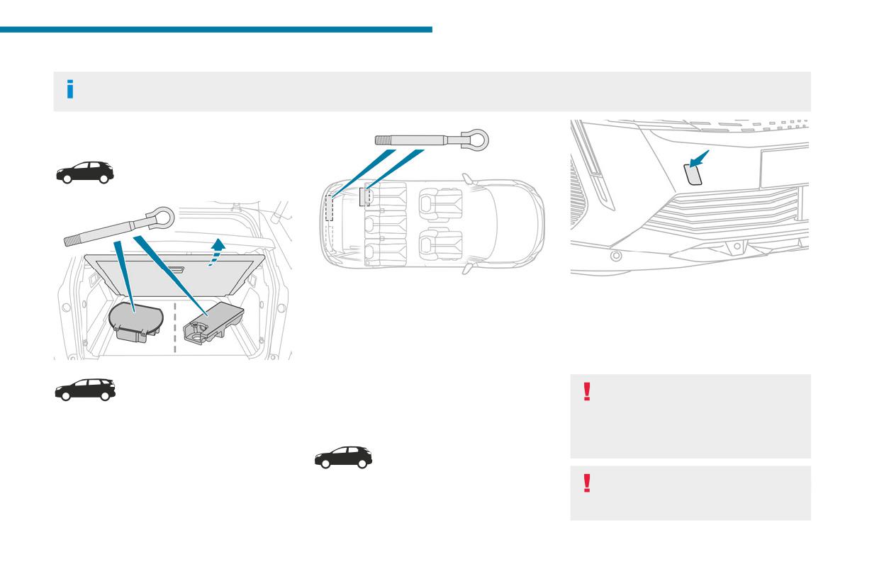
In the event of a breakdown
4WD: 4-wheel drive.
8
In case of battery or electric parking brake failure, it is essential to call a professional using flatbed recovery vehicles (excluding manual gearbox).
Accessing the tools
Depending on version, the towing eye is stored
► Unclip the cover by pressing at its top left-
either in the interior trim of the boot sill, left-hand
hand corner.
side, or in a bag behind the left-hand rear seat.
To be towed:
The towing eye is stored in a tool box, under the
► Screw the towing eye in fully.
boot floor.
► Install the towbar.
For more information on accessing the Tool kit,
► Put the gearbox into neutral.
refer to the corresponding section.
Failure to observe this instruction could
result in damage to certain components
Towing your vehicle
(e.g. braking, transmission) and to the
To access the front screw thread:
absence of braking assistance the next time
the engine is started.
Automatic gearbox
Never tow the vehicle with the driving
wheels on the ground and the engine off.
231
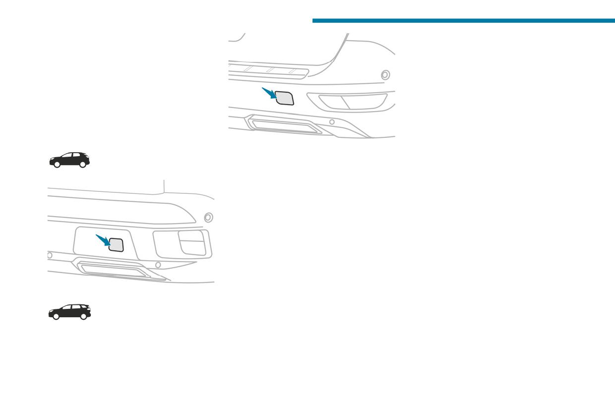
In the event of a breakdown
► Unlock the steering and release the parking
brake.
► Switch on the hazard warning lamps on both
vehicles in accordance with the legislation in
force in the country in which you are driving.
► Move off gently, drive slowly and only for a
short distance.
Towing another vehicle
To access the rear screw thread:
► Unclip the cover by pressing at its left-hand
section.
► Pull the cover downwards.
To tow:
► Screw the towing eye in fully.
► Install the towbar.
► Switch on the hazard warning lamps on both
vehicles.
► Move off gently, drive slowly and only for a
short distance.
232
Technical data
The maximum authorised nose weight
Engine technical data and
9
corresponds to the weight permitted on the
towed loads
towball.
When exterior temperatures are high, the
Engines
vehicle performance may be limited in
The engine characteristics are given in the
order to protect the engine. When the exterior
vehicle's registration document, as well as in
temperature is higher than 37°C, reduce the
sales brochures.
towed weight.
Only the values available at the time of
publication are presented in the tables.
Towing even with a lightly loaded vehicle
Contact a PEUGEOT dealer or a qualified
can adversely affect its road holding.
workshop to obtain missing values.
Braking distances are increased when towing
The maximum power corresponds to the
a trailer.
value type-approved on a test bed, as
When using a vehicle to tow, never exceed
defined by the Regulation EU 715/2007.
a speed of 62 mph (100 km/h) (observe the
local legislation in force).
For more information, contact a PEUGEOT
dealer or a qualified workshop.
Weights and towed loads
The weights and towed loads relating to
the vehicle are indicated on the registration
document, as well as in sales brochures.
These values are also indicated on the
manufacturer's plate or label.
For more information, contact a PEUGEOT
dealer or a qualified workshop.
The GTW (Gross Train Weight) and towed load
values indicated are valid up to a maximum
altitude of 1,000 metres. The towed load value
must be reduced by 10% for each additional
1,000 metres of altitude.
233

Technical data
Engines and towed loads - Petrol
Engines
PureTech 130 S&S BVM6
PureTech 130 S&S EAT8
Gearboxes
BVM6
EAT8
(Manual 6-speed)
(Auto. 8-speed)
Codes
EB2ADTS MB6 STT
EB2ADTS ATN8 STT
Model codes
HNSM/C
HNSM/S
HNSU/C
HNSU/S
HNSC/C
HNSC/S
Body styles
3008
5008
3008
5008
Cubic capacity (cc)
1,199
1,199
Max. power: EC standard (kW)
96
96
Fuel
Unleaded
Unleaded
Braked trailer (within the GTW limit) (kg)
1,400
1,280
1,150
950
on a 10% or 12% gradient
Unbraked trailer (kg)
690
690
690
750
Maximum authorised nose weight (kg)
80
72
80
72
234
Technical data
Engines
THP 150 EAT6
THP 165 EAT6
PureTech 180 S&S EAT8
9
Gearboxes
EAT6
EAT6
EAT8
(Auto. 6-speed)
(Auto. 6-speed)
(Auto. 8-speed)
Codes
EP6FDTMD AT6III
EP6FDTM AT6III
EP6FADTXD ATN8 STT
Model codes
5GXV/C
5GXV/S
5GYV/C
5GYV/S
5GFU/C
5GFU/S
5GYW/C
5GYW/S
5GYZ/C
5GYZ/S
5GSD/C
Body styles
3008
5008
3008
5008
3008
5008
Cubic capacity (cc)
1,598
1,598
1,598
Max. power: EC standard (kW)
110
121.4
133
Fuel
Unleaded
Unleaded
Unleaded
Braked trailer (within the GTW limit) (kg)
600
600
600
600
1,500
1,400
on a 10% or 12% gradient
1,550*
1,350*
Unbraked trailer (kg)
600
600
600
600
750
750
Maximum authorised nose weight (kg)
80
72
80
72
80
72
* For Australia only.
235

Technical data
Engines and towed loads - BlueHDi Diesel
Engines
BlueHDi 130 S&S EAT8
Gearboxes
EAT8
(Auto. 8-speed)
Codes
DV5RC ATN8 STT
Model codes
YHZU/C
YHZU/S
Body styles
3008
5008
Cubic capacity (cc)
1,499
Max. power: EC standard (kW)
96
Fuel
Diesel
Braked trailer (within the GTW limit) (kg)
1,300
1,200
on a 10% or 12% gradient
Unbraked trailer (kg)
750
750
Maximum authorised nose weight (kg)
80
72
236

Technical data
Engines and towed loads - Hybrid
9
HYBRID 136 e-DCS6
Codes
EB2LTDH2 EDCT6
Model codes
HPYE/C
HPYE/S
MR...
Body styles
3008
5008
Braked trailer (within the GTW limit) (kg)
1,250
1,050
on a 10% or 12% gradient
Unbraked trailer (kg)
750
600
Maximum authorised nose weight (kg)
70
70
Petrol engines
PureTech 136
Gearboxes
Electric dual-clutch automatic 6-speed
Cubic capacity (cc)
1,199
Max. power: EC standard (kW)
100
Fuel
Unleaded
Electric motor
Technology
Synchronous with permanent magnets
Max. power: EC standard (kW)
21
Traction battery
Technology
Lithium-Ion
Voltage (Volts DC)
48
Installed capacity (kWh)
0.9
237

Technical data
Engines and towed loads - Rechargeable hybrid
HYBRID 180 e-EAT8
HYBRID 225 e-EAT8
HYBRID4 300 e-EAT8
Codes
EP6FADTXDHPE EATN8
EP6FADTXDHPD EATN8
EP6FADTXHPP EATN8 AWD
FWD
FWD
Model codes
DGLU/C
DGZU/C
5GBU/C
M4...
Braked trailer (within the GTW limit) (kg)
1,250
1,250
1,250
on a 10% or 12% gradient
Unbraked trailer (kg)
600
750
750
Maximum authorised nose weight (kg)
70
70
70
Petrol engines
PureTech 150
PureTech 180
PureTech 200
Gearboxes
Electric automatic 8-speed
Electric automatic 8-speed
Electric automatic 8-speed
Cubic capacity (cc)
1,598
1,598
1,598
Max. power: EC standard (kW)
110
132
147
Fuel
Unleaded
Unleaded
Unleaded
Electric motor(s)
Technology
Synchronous with permanent magnets
Max. power: EC standard (kW)
81
81
Front: 81
Rear: 83
Traction battery
Technology
Lithium-Ion
Voltage (Volts AC)
240-400
240-400
240-400
Installed capacity (kWh)
12.4
14.2
14.2
Combined power (kW)
133
165
220
238
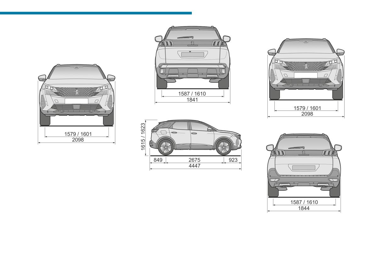
Technical data
5008
Dimensions (mm)
9
These dimensions have been measured on an
unladen vehicle.
3008
239
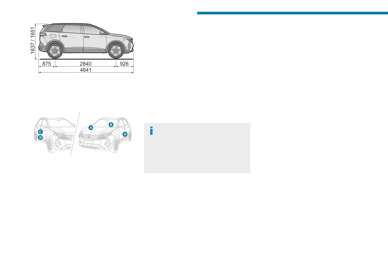
Technical data
- European whole vehicle type approval
number.
- Vehicle Identification number (VIN).
- Gross vehicle weight (GVW).
- Gross train weight (GTW).
- Maximum weight on the front axle.
- Maximum weight on the rear axle.
D. Tyres/paint code label.
Affixed to the driver's door.
Bears the following information about the tyres:
Identification markings
- Tyre pressures, unladen and laden.
- Tyre specification, made up of the dimensions
Various visible markings for vehicle identification
and type as well as the load and speed indices.
and vehicle search.
- Spare tyre inflation pressure.
Also indicates the paint colour code.
The vehicle may be originally equipped
with tyres with higher load and speed
indices than those indicated on the label,
without affecting tyre pressure (on cold tyres).
In the event of a change in the type of tyres,
A. Vehicle Identification Number (VIN), under
contact a PEUGEOT dealer for the tyre fits
the bonnet.
approved for the vehicle.
Stamped on the chassis.
B. Vehicle Identification Number (VIN), on the
dashboard.
Printed on an adhesive label visible through the
windscreen.
C. Manufacturer's label.
Affixed to the right-hand door.
Bears the following information:
– Manufacturer’s name.
240