Peugeot 1007 Dag (2008.5). Instruction - part 8
 

  Index      Peugeot     Peugeot 1007 Dag 2008.5 - instruction in english


Search            


Content   ..  6  7  8  9   ..


Peugeot 1007 Dag (2008.5). Instruction - part 8


7

106

  Operating fault 

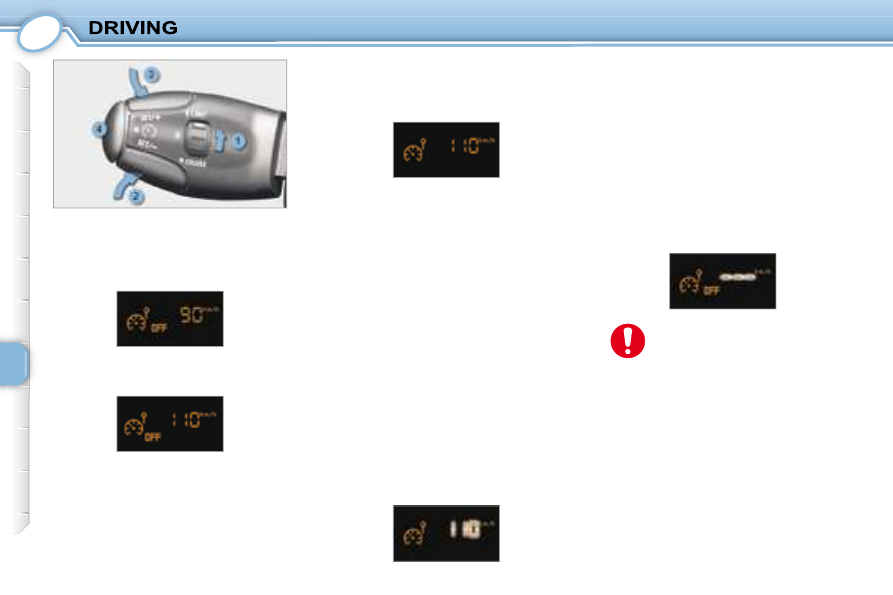
 If a speed limiter malfunction occurs, 

the  speed  is  replaced  by  fl ashing 

dashes. Contact a  PEUGEOT  dealer 
to have the system checked. 

  Activating/deactivating the limiter 
      Switch  the  speed  limiter  on  by 

pressing button  4 . 

  Programming 

      Place the dial  1  in the  LIMIT  posi-

tion. The limiter is not yet active. 
By  default,  the  display  indicates 
the last speed programmed: 

  Return to normal driving 

      Turn  dial   1   to  position   "0" :  the 

speed limiter mode is  deselected. 
The  display  returns  to  the  dis-
tance recorder.   

  In  the  event  of  a  steep  de-
scent  or  sharp  acceleration, 
the  speed  limiter  will  not  be 
able  to  prevent  the  vehicle 
from  exceeding  the  pro-
grammed speed. 

 In any event, the speed limiter cannot 
replace  the  need  to  observe  speed 
limits, nor can it replace the need for 
vigilance  and  responsibility  on  the 
part of the driver. 
 The driver must remain alert and stay 
in complete control of his vehicle. 
 To  prevent  the  mat  from  becoming 
caught under the pedals: 
   -  

ensure that the mat is positioned 
correctly. 

  -  

never fi t one mat on top of another.   

     Set  the  speed  value  by  press-

ing  button   2   or   3

   (e.g.:  70  mph 

(110 km/h)).  

 You can then change the programmed 
speed using buttons  2  and  3 : 
   -  

by + or - 1 mph (1 km/h) = short 

press, 

  -  

by + or - 5 mph (5 km/h) = long press, 

  -  

in steps of + or - 5 mph (5 km/h) = 

maintained press.  

  Exceeding the programmed 
speed 

 Pressing  the  accelerator  pedal  to 
exceed  the  programmed  speed  will 
not have any effect, unless you press 
the pedal  

fi rmly  passing the  point of 

resistance . 
 The speed limiter is deactivated tem-
porarily and the programmed speed, 

which is still displayed, fl ashes. 
 Returning to the programmed speed, 
by  means  of  intentional  or  uninten-
tional  deceleration  of  the  vehicle, 

cancels  the  fl ashing  automatically 

and reactivates the speed limiter.  

     Switch  the  speed  limiter  off  by 

pressing  button   4 :  the  display 

confi rms that it is off (OFF). 

     Switch the speed limiter back on 

by pressing button  4  again.    

7

107

     CRUISE CONTROL 

 This cruise control, of the new genera-
tion,  is  linked  with  the  speed  limiter.  It 
has a display on the instrument panel 
to  indicate  the  memorised  reference 
speed. 
 It  enables  the  vehicle  to  maintain  a 
steady  speed  programmed  by  the 
driver. 
 The  cruise  control  is   switched  on  
manually:  it  requires  a  minimum  ve-

hicle speed of 25 mph (40 km/h) and 

fourth gear must be engaged on the 
manual gearbox. 
 The  cruise  control  is   switched  off  
by  means  of  a  manual  action  or  by 
pressing the brake or clutch pedal or 
in the event of activation of the ESP. 
 By pressing the accelerator pedal, it is 
possible  to  exceed  the  programmed 
speed temporarily. 
 To  return  to  the  programmed  speed, 
simply release the accelerator pedal. 
 Switching  off  the  ignition  or  turning 
the  dial  cancels  any  programmed 
speed value. 

  Instrument panel display 

 The 

programmed 

information 

is 

grouped  together  on  the  instrument 
panel display. 
  5.    Cruise control on/off indication 
  6.    Cruise control mode selection in-

dication 

  7.    Programmed speed value  

  Steering wheel controls 

 This  system's  controls  are  grouped 
together on lever  A . 
   1.   Cruise control mode selection dial 
  2.   Value decrease button 
  3.   Value increase button 
  4.   Cruise control on/off button   

7

108

  Exceeding the programmed speed 

 Intentional or unintentional  exceeding 
of  the  programmed  speed  results  in 

fl ashing  of  the  programmed  speed 

on the display. 
 Returning to the programmed speed, 
by  means  of  intentional  or  uninten-
tional  deceleration  of  the  vehicle, 

cancels the fl ashing automatically.  

 Using the accelerator: 
      exceed the memorised speed until 

the required speed is reached, 

     press button  2  or  3 .  

  Programming 

      Place  switch   1   in  the   CRUISE  

position.  The  cruise  control  is 
not yet active and no speed has 
been  memorised.  The  display 
 indicates: 

  Cancelling the cruise control 
      Switch  the  cruise  control  off  by 

pressing  button   4 :  the  display 

confi rms that it is off (OFF).   

 When  changing  the  memo-
rised  reference  speed  by 
means  of  a  maintained 
press,  pay  attention  as 
the  speed  can  increase  or 
 decrease rapidly. 

 Do not use the cruise control on slip-

pery roads or in heavy traffi c. 
 In  the  event  of  a  steep  slope,  the 
cruise  control  cannot  prevent  the 
vehicle  from  exceeding  the  pro-
grammed speed. 
 In any event, the cruise control can-
not  replace  the  need  to  comply  with 
speed  limits,  nor  can  it  replace  the 
need  for  vigilance  and  responsibility 
on the part of the driver. 
 To  prevent  the  mat  from  becoming 
caught under the pedals: 
   -  

ensure that the mat is positioned 
correctly. 

  -  

never fi t one mat on top of another.  

 It is advisable to keep your feet near 
the pedals.  

     Set  the  programmed  speed  by 

accelerating  to  the  required 
speed,  then  press  button   2   or   3  

(e.g.: 70 mph (110 km/h)).  

  Return to normal driving 

      Turn  dial   1   to  position   "0" :  the 

cruise  control  mode  is  dese-
lected. The display returns to the 
distance recorder.   

  Operating fault 

 If a cruise control malfunction occurs, 

the  speed  is  replaced  by  fl ashing 

dashes. Contact a  PEUGEOT  dealer 
to have the system checked. 

 You can then change the programmed 
speed using buttons  2  and  3 : 
   -  

by + or - 1 mph (1 km/h) = short 

press, 

  -  

by + or - 5 mph (5 km/h) = long press, 

  -  

in steps of + or - 5 mph (5 km/h) 

= maintained press.  

  Reactivating the cruise control 
      Switch the cruise control back on 

by pressing button  4  again.    

7

109

     VISUAL AND AUDIBLE REAR 
PARKING ASSISTANCE 

 This system consists of four proximity 
sensors, located in the rear bumper, 
and a special speaker. 
 This  detects  any  obstacle  (person, 

vehicle,  tree,  gate,  etc.)  behind  the 
vehicle. 

Nevertheless, 

it 

cannot 

 detect  obstacles  located  just  below 
the bumper. 
 An  object,  such  as  a  stake,  a  road-
works  cone  or  any  other  similar 
 object may be detected at the begin-
ning  of  the  manoeuvre,  but  may  no 
longer be detected when the vehicle 
comes close to it.  

  Detection zone   

  Activation 

 The  system  is  activated  as  soon  as 
reverse  gear  is  engaged,  accompa-
nied  by  an  audible  signal. The  proxi-
mity information is given by: 
   -  

an  audible  signal,  which  beco-
mes  more  rapid  as  the  vehicle 
approaches the obstacle. 

  -  

a  graphic  on  the  multifunction 
display,  with  blocks  which  be-
come  increasingly  close  to  the 
vehicle.  

 When the distance between the rear 
of the vehicle and the obstacle is less 
than  thirty  centimetres,  the   audible 
signal  becomes  continuous  and  the 
"Danger"  symbol  appears  on  the 
multifunction display. 
 On  completion  of  the  manoeuvre, 
when you exit reverse gear, the sys-
tem becomes inactive. 
 The  rear  parking  assistance  sys-
tem  cannot,  in  any  circumstances, 
take  the  place  of  the  vigilance  and 
 responsibility of the driver.  

7

110

 If there is an operating fault, 
when  reverse  gear  is  enga-
ged,  the  service  warning 
light  comes  on,  accompa-
nied  by  an  audible  signal 

(short bleep) and a message 

on the multifunction display. 

 In bad or wintry weather, ensure that 
the  sensors  are  not  covered  with 
mud, frost or snow.  

  Deactivation 

 With the engine running, press button  A  
to  deactivate  the  system  permanently. 
The indicator light on the button comes 
on. 
 The  system  will  be  deactivated 
 automatically when towing a trailer or 

when a bicycle carrier is fi tted (vehicle 

fi tted with a towbar or bicycle carrier 

recommended by  PEUGEOT ).  

  Reactivation 

 Press  button   A   again  to  reactivate 
the system. The indicator light on the 
button is switched off. 

8

112

  From  outside:   lift  the  catch   A   and 
raise the bonnet. 

  Bonnet strut 

 Secure  the  strut  to  hold  the  bonnet 
open. 
 Before  closing  the  bonnet,  replace 
the strut in its housing. 

  To close 
 Lower  the  bonnet  and  release  it  at 
the  end  of  its  travel.  Check  that  the 
bonnet is properly locked. 

       OPENING THE BONNET 

  From inside:  pull the handle on the 
left-hand side under the fascia. 

 RUNNING OUT OF FUEL 
(DIESEL) 

 If  your  vehicle  is  fi tted  with  an  HDI 

engine,  the  fuel  circuit  must  be  rep-
rimed  if  you  run  out  of  fuel  (refer  to 
the corresponding graphic). 
 This  system  consists  of  a  repriming 
pump and a transparent pipe. 

  1.4 litre Turbo HDI engine 

      Open the bonnet. 
  

   Fill the fuel tank with at least fi ve 

litres of diesel. 

     Squeeze  and  release  the  rep-

riming pump until fuel appears in 
the transparent pipe. 

     Operate  the  starter  until  the  en-

gine starts. 

     Close the bonnet.   

  1.6 litre Turbo HDI 16V engine 

      Open the bonnet. 
     Fill  the  fuel  tank  with  at  least 

fi ve litres of diesel. 

     Unclip  the  style  cover  to  gain

access to the repriming pump. 

     Squeeze  and  release  the  rep-

riming  pump  until  fuel  appears 
in  the  transparent  pipe  with  the 
green connector. 

     Operate  the  starter  until  the 

engine starts. 

     Put the style cover back in posi-

tion and clip it in place. 

     Close the bonnet.   

 Opening  the  bonnet  may 
cause 

serious 

injuries, 

please observe the following 
recommendations: 

   -  

protect your hands and clothing, 

  -  

always  allow  the  engine  to  cool 
before opening the bonnet, 

  -  

place  the  strut  in  its  housing  on 
the wing correctly, 

  -  

check  that  the  bonnet  is  fi rmly 

secured in the open position, 

  -  

be  aware  of  gusts  of  wind  as 
they  could  cause  the  bonnet  to 
close suddenly.    

8

113

         1.4 LITRE AND 1.6 LITRE
16V PETROL ENGINES 

   1.   Coolant reservoir. 

  2.   Windscreen/headlamp wash 

reservoir. 

  3.

   Passenger compartment fi lter. 

  4.

   Brake fl uid reservoir. 

  5.   Fuse box. 

  6.   Battery. 

  7.

   Air fi lter. 

  8.   Dipstick. 

  9.

   Engine oil fi ller cap.  

8

114

         1.4 LITRE HDI AND 
1.6 LITRE HDI PEF TURBO 
DIESEL ENGINES 

   1.   Coolant reservoir. 

  2.   Windscreen/headlamp wash 

reservoir. 

  3.

   Passenger compartment fi lter. 

  4.   Priming pump. 

  5.

   Air fi lter. 

  6.

   Brake fl uid reservoir. 

  7.   Fuse box. 

  8.   Battery. 

  9.   Dipstick. 

  10.

   Engine oil fi ller cap.  

8

115

                                                                       CHECKING THE LEVELS 

 There  are  two  marks  on 
the dipstick: 
  A  = maximum 
 Never fi ll past this mark. 
  B  = minimum 

  Dipstick 

  Oil change 
 According to the information given in 
the servicing booklet.  

  Changing the brake fluid 

 The  brake  fl uid  must  be 

changed  at  the  intervals 
stated,  according  to  the 
manufacturer's 

servicing 

schedule. 

 Use fl uids recommended by the man-

ufacturer, which fulfi l DOT4 standards.  

  Windscreen and headlamp 
wash level 

 For  best  quality  cleaning  and 
for  your  safety,  we  would  ad-
vise  that  you  use  products 
recommended by  PEUGEOT . 

 When the level is low, this is indicated 
by an audible signal and a message 
on the multifunction display.  

  Viscosity selection 
 In  all  cases,  the  oil  selected  must 
meet  the  manufacturer's  require-
ments.   

  Cooling system 

 Use  the  fl uid  recommended  by  the 

manufacturer. 
 When  the  engine  is  warm,  the  tem-
perature  of  the  coolant  is  controlled 
by the engine fan. As this fan can ope
rate with the ignition key removed and 
because  the  cooling  system  is  pres-
surised, wait for at least one hour after 
the engine has stopped before carry-
ing out any work. 
 Slacken  the  cap  by  two  turns  to  re-
lease  the  pressure  to  prevent  any 
risk  of  scalding.  When  the  pressure 
has  dropped,  remove  the  cap  and 
top up the level. 

  Diesel additive level (Diesel 
with particle emission filter) 

 Lighting of the service warning light, 
accompanied  by  a  message  and  an 
audible signal, indicates that the die-
sel additive level is low. 
 This additive must be topped up. 
 Contact a  PEUGEOT  dealer as soon 
as possible.  

 To  maintain  the  reliability  of 
engines and emission control 
systems, the use of additives 
in engine oil is prohibited.  

  Used oil 

 Avoid  prolonged  contact  of  used  oil 
with the skin. 
 Brake  fl uid  is  harmful  to  health  and 

very corrosive. 

  Note :  the  coolant  does  not  need  to 
be changed.  

 The  level  must  always  be 
above  the  MIN  mark  and 
close to the MAX mark. 

 Do  not  dispose  of  used  oil, 

brake  fl uid  or  coolant  into 

drains or into the ground.  

  Oil level 

 Check  the  level  regularly 
and  top  up  between  chang-
es. The maximum consump-
tion  is  0.5 l  per  600  miles 
(1 000 km). 

 Check the level with the vehicle level, 
engine cold, using the oil level gauge 
on  the  instrument  panel  or  the  dip-
stick. 

8

116

 CHECKS 

  Handbrake 

 Where the handbrake travel 
is too great or there is a re-
duction  in  the  performance 
of  the  system,  the  hand-
brake  should  be  adjusted, 

even between services. 
 Have the system checked by a  PEUGEOT  

dealer.  

  Air filter and passenger compartment filter 

  Particle emission filter (Diesel) 

 It  is  imperative  that  maintenance  of 

the  particle  emission  fi lter  is  carried 

out by a  PEUGEOT  dealer in accord-
ance with the manufacturer's servicing 
schedule. 

  Brake pads 

 Brake  pad  wear  depends 
on  the  style  of  driving,  in 
particular for vehicles which 
are used in town, over short 
distances. 

  Brake disc/drum wear status 

 For  any  information  relating  to  the 
wear of the surfaces of the discs and 
drums, contact a  PEUGEOT  dealer.  

  Oil filter 

 Change the fi lter regularly, in 

accordance with the servic-
ing schedule.  

 It  may  be  necessary  to 
check  the  thickness  of  the 
pads, even between services. 
 Unless there is a leak in the 

circuit,  a  drop  in  the  brake  fl uid  level 

indicates  that  the  brake  pads  are 
worn.  

 At  the  start  of  winter,  have 
your  battery  checked  by  a 
 PEUGEOT  dealer.  

 Refer to the servicing book-
let  for  information  on  the 
replacement 

interval 

for 

these components. 
 Depending  on  the  environ-

ment  (dusty  atmosphere...)  and  the 
use  of  the  vehicle  (urban  driving...), 
 change  them  twice  as  often,  if  ne
cessary
  (refer to the "Engines" para-
graph). 
 A  clogged  passenger  compartment 

fi lter may have an adverse effect on 

the performance of the air condition-
ing  system  and  produce  unpleasant 
odours.  

 Following prolonged opera-
tion  of  the  vehicle  at  very 
low  speed  or  at  idle,  you 
may, in exceptional circum-

stances,  notice  steam  coming  from 
the exhaust during acceleration. This 
has  no  effect  on  the  performance  of 
the vehicle or on the environment.  

  Battery 

Manual gearbox

This  does  not  require  an 

oil  change.  Have  the  level 

checked in accordance with 

the manufacturer's servicing 

schedule.

Only  use  products  recom-
mended  by  PEUGEOT  or 
products of equivalent qual-
ity and characteristics.

To  ensure  best  performance  from 
components  as  important  as  the 
braking  system,  PEUGEOT  selects 

and offers quite specifi c products.
To  prevent  damage  to  the  electri-
cal  units,  high  pressure  washing  of 
the  engine  compartment  is  strictly 
prohibited.

To  check  the  main  levels 
and  certain  components, 
in  accordance  with  the 
manufacturer's  servicing 

schedule,  refer  to  the  pages  of  the 
servicing booklet which correspond 
to your vehicle's engine.

9

117

  Parking the vehicle 
   -  

If  possible,  park  the  vehicle  on 
level,  stable  and  non-slippery 
ground. 

  -  

It is imperative that you ensure that 
the occupants get out of the vehi-
cle and wait in a safe location. 

  -  

Apply  the  handbrake,  switch  off 

the  ignition  and  engage  fi rst  or 

reverse  gear  (position   R   for  the 
"2 Tronic" gearbox).   

                   CHANGING A WHEEL  

   1.   Jack with integrated handle. 
  2.   Chock. 
  3.   Wheelbrace. 
  4.   Extension. 
  5.   "Bolt cover" tool. 
  6.   Removable towing eye.  

  Access to the spare wheel and 
the jack 
 The wheel is located outside the ve-

hicle, under the rear fl oor, supported 

by a metal carrier. 
   -  

Unclip  the  cover  to  gain  access 
to the spare wheel carrier retain-
ing  bolt,  located  on  the  inside 
near the closing system. 

  -  

Using the wheelbrace  3  and the 
extension   4 ,  slacken  the  spare 
wheel carrier retaining bolt. 

  -  

Lift  the  carrier  to  release  the 
hook rearwards, then lower it. 

  -  

Remove  the  spare  wheel  and 
the box. 

  -  

Remove the jack  1  from the box.    

  Tools provided 
 The jack is stored in a box in the cen-
tre of the spare wheel. The chock is 

fi xed on the side of the box. 
 The other tools are stored in a case 
in the left boot trim. 

  Note:

   if  your  vehicle  is  fi tted  with  a 

towbar,  the  case  is  stored  in  the  left 

storage  tray  (located  in  the  fl oor  of 

the rear footwell).  

9

118

  Removing a wheel 

   -  

Place  the  chock   2   (integrated 
with  the  box)  at  the  rear  of  the 
wheel  diagonally  opposite  the 
wheel to be changed. 

  -  

Remove  the  wheel  trim,  using 
the  wheelbrace   3 ,  by  pulling  at 
the valve passage hole. 

  -  

Remove  the  chrome-plated  bolt 
covers  and  the  plastic  cover  from 
the bolts using the "bolt cover" tool  5  
(Special features of alloy wheels). 

  -  

Slacken the wheel bolts. 

  -  

Place the jack  1  under one of the 
four locating points  A  on the sub-
frame closest to the wheel to be 
changed.  Ensure  that  the  entire 
surface of the jack base plate is 
in contact with the ground. 

  -  

Extend the jack, completely unscrew 
the bolts and remove the wheel.   

  Refitting the wheel 

   -  

Position the wheel on the hub. 

  -  

Lightly  pre-tighten  the  bolts  us-
ing the wheelbrace  3 . 

  -  

Compress the jack  1  and release it. 

  -  

Fully  tighten  the  bolts  using  the 
wheelbrace. 

  -  

Replace  the  trim,  starting  at  the 
valve passage hole, and press it 
on using the palm of the hand.   

  For  your  safety,  always 
change a wheel:
  

  -  

Stow  the  tools  in the  case,  then 
put it back in the left boot trim.  

 The jack and the tool kit are specifi c 

to your vehicle. Do not use them for 
other purposes. 

  Replacing the wheel in the 
carrier 

   -  

Replace the jack  1  in the box. 

  -  

Replace the box in the wheel. 

  -  

Replace the wheel in the carrier. 

  -  

Lift  the  wheel  then  the  carrier 
and reposition the hook. 

  -  

Do  not  forget  to  fully  tighten  the 
spare wheel carrier retaining bolt. 

  After changing the wheel 
   -  

Have  the  tightening  of  the  bolts 
and  the  pressure  of  the  spare 
tyre  checked  as  soon  as  possi-
ble by a  PEUGEOT  dealer. 

  -  

Do  not  exceed  its  maximum  au-
thorised speed: 50 mph (80 km/h). 

  -  

Have the punctured tyre repaired 
and  replace  it  on  the  vehicle  as 
soon as possible. 

  -  

15 and 16 inch punctured wheels 
cannot be placed in the carrier.    

   -  

on level, stable and non-slippery 
ground, 

  -  

with the handbrake applied, 

  -  

with fi rst or reverse gear engaged 

(position  R  for the "2 Tronic" gear-
box), 

  -  

with the vehicle chocked, 

  -  

never  go  underneath  a  vehicle 
raised using a jack (use an axle 
stand).  

9

119

  Special features of alloy 
wheels 

  Fitting the spare wheel 
 If  your  vehicle  is  fi tted  with  a  steel 

spare wheel, when fi tting it, it is  nor-

mal  when tightening the bolts to no-
tice  that  the  washers  do  not  come 
into  contact  with  the  rim.  The  spare 
wheel is secured by the cone shape 
of each bolt.  

  Anti-theft bolts 

 If your wheels are fi tted with an anti-

theft bolt (one per wheel), the chrome 
trim  must  be  removed  before  un-
screwing the bolt using the anti-theft 
socket and the wheelbrace.  

  Fitting snow tyres 
 If you fi t snow tyres mounted on steel 

wheels  onto  your  vehicle,  it  is   es-
sential
  to use special bolts available 
from  PEUGEOT  dealers. 
  Wheels  equipped  with  195/50R16 

tyres  cannot  be  fi tted  with  snow 

chains.  
  For  further  information,  contact  a    
 PEUGEOT   dealer.   

  Bolt covers 
 Alloy  wheel  bolts  are  covered  by 
chrome trims. 
 Use  the  yellow  tool  to  remove  the 
trims before slackening the bolts.  

9

120

                     CHANGING A BULB 

  2 -  Dipped beam headlamps/

Main beam headlamps 
(H4 - 60/55 W) 

   -  

Remove the plastic cover  B . 

  -  

Disconnect the connector. 

  -  

Push  the  spring   D   towards  the 
right,  as  indicated  on  the  head-
lamp. 

  -  

Remove and replace the bulb.   

  3 -  Direction indicators 

(PY 21 W amber) 

   -  

Turn the bulb holder  C  a quarter 
of a turn and remove it. 

  -  

Turn the bulb a quarter of a turn. 

  -  

Remove the bulb and change it.  

 In certain weather conditions 
(low temperatures, humidity), 
 the presence of condensa-
tion  on  the  inside  of  the 

headlamp glass is normal ; it disap-
pears  a  few  minutes  after  the  lights 
have been switched on. 

  Front lights 

  1 -  Side lights (W 5 W) 
   -  

Remove the plastic cover  A . 

  -  

Remove the bulb holder. 

  -  

Remove the bulb and change it.   

9

121

 Only use H4 bulbs manufac-
tured by: 
   -   GE/TUNGSRAM. 
  -   PHILIPS, 
  -   OSRAM,  

 to avoid damaging the headlamps. 

  Direction indicator side repeaters 
(WY 5 W amber) 
   -  

Push  the  repeater  cover  for-
wards and release it. 

  -  

Remove 

the 

repeater 

and 

change it.  

 Contact a  PEUGEOT  dealer to obtain 
a new bulb. 

  4 -  Front fog lamps (H1 - 55 W) 
   -  

Open the fl ap, located under the 

mud guard, to gain access to the 
screw. 

  -  

Remove the screw. 

  -  

Push  the  assembly  outwards  to 
extract it. 

  -  

Disconnect the connector. 

  -  

Turn  the  protective  cover   A   a 
quarter of a turn. 

  -  

Disconnect the connector  B . 

  -  

Move aside the springs  C . 

  -  

Remove the bulb and change it.  

  Amber  coloured  bulbs  (di-
rection  indicators  and  side 
repeaters) must be replaced 

by  bulbs  of  identical  specifi -

cation and colour.  

 These meet the anti-UV (ultra-violet) 

specifi cations necessary for the cor-

rect  operation  and  reliability  of  the 
headlamps. 
 The headlamps are fi tted with a poly-

carbonate lens coated with a protec-
tive varnish. You are strongly advised 
to avoid cleaning them using a dry or 
abrasive  cloth  and  using  detergent 
products or solvents. 
 Use  a  soft,  damp  cloth  with  soapy 
water.  

 To refi t, proceed in the reverse order 

to removal. 
 It is  essential

  that the fl ap is closed.   

9

122

  Rear lights 

   1.    Brake/side lights 

(P21 W/5 W).  

  2.    Direction indicators (P21 W).  
  3.    Reversing light (P21 W), right 

side.   


 Fog lamp (P21 W), left side.   

 These  4  bulbs  are  changed  by  re-
moving the light: 
   

   Remove  the  access  fl ap  in  the 

corresponding  boot  side  trim  to 
access the light, 

  

   Remove the two light fi xing nuts 

inside the boot, 

     Unclip the harness, 
     Remove the light pressing on the 

retaining tabs, 

     Remove the seal, 

     Remove the bulb holder moving 

aside the two tabs  A , 

     Turn the bulb a quarter of a turn, 
     Remove the bulb and change it.  
  Note:   if  necessary,  use  the  wheel-
brace to remove the nuts. 
 When  refi tting,  proceed  in  the  re-

verse order and take care to position 
the bulb holder, the seal and the light 
correctly.  

  Third brake light 
(4 W 5 W bulbs) 

      Using a 10 mm box spanner, un-

screw the 2 fi xing nuts  A . 

     Release  the  lamp  unit  by  push-

ing it outwards. 

     Disconnect  the  connector  and 

the rear wash-wipe pipe. 

     Turn the bulb holder a quarter of 

a turn and remove it. 

     Remove the bulb and change it.  
 When  refi tting,  proceed  in  the  re-

verse order and ensure that the lamp 
unit seal and the rear wash-wipe pipe 
have been put back in place correctly. 
 Do not tighten the nuts more than is 
necessary at the risk of breaking the 
light.  

  Number plate lights (W 5 W) 

      Insert a thin screwdriver into one 

of the external holes of the lens. 

     Push it outwards to unclip it. 
     Remove the lens. 
     Remove the bulb and change it.   


Content   ..  6  7  8  9   ..