Index Peugeot Peugeot 4C - instruction 2015 year in english
Search
Content .. 6 7 8 9 ..
Peugeot 4C (2015 year). Instruction - part 8
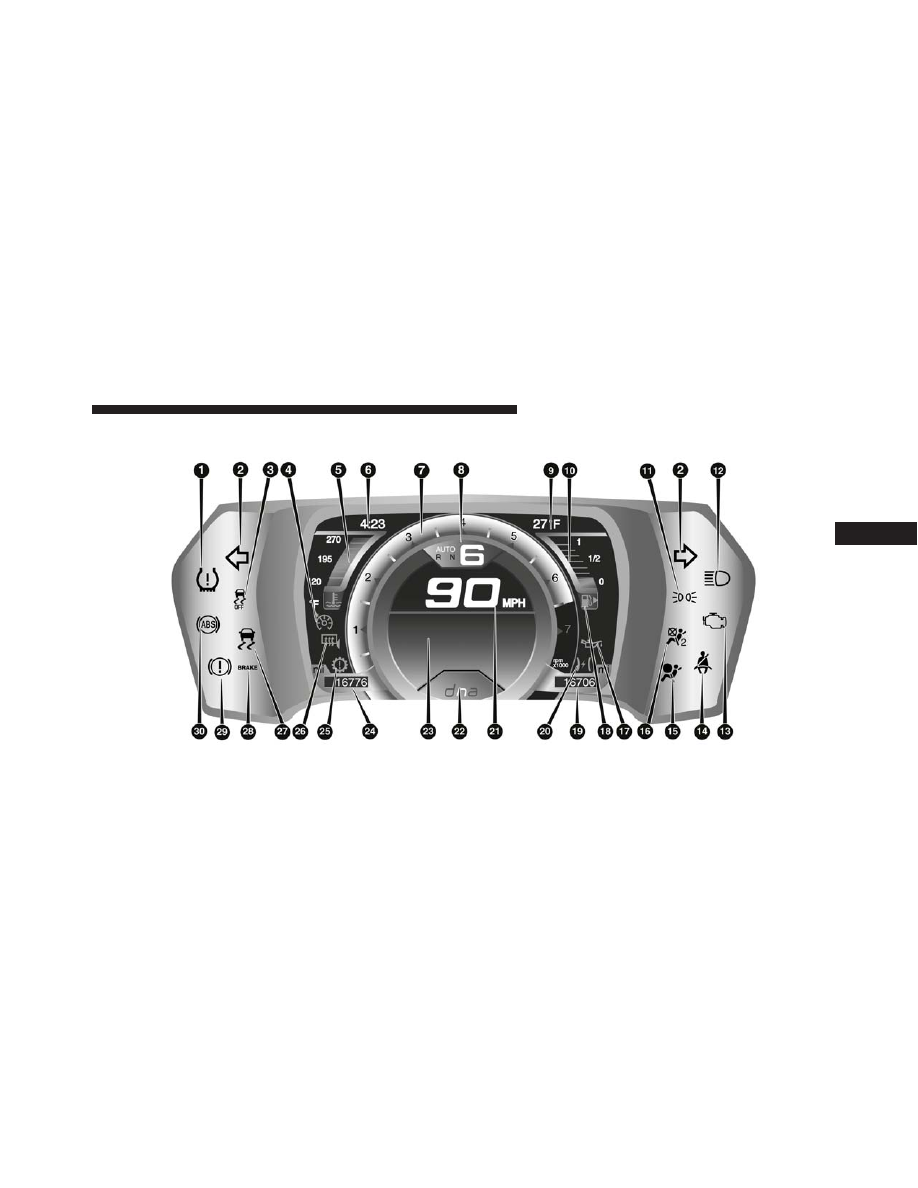
INSTRUMENT CLUSTER
4
UNDERSTANDING YOUR INSTRUMENT PANEL
111