Peugeot 4C (2015 year). Instruction - part 6


  Index      Peugeot     Peugeot 4C - instruction 2015 year in english


Search            


Content   ..  4  5  6  7   ..


Peugeot 4C (2015 year). Instruction - part 6


WARNING! (Continued)

• Do not allow people to ride in any area of your

vehicle that is not equipped with seats and seat
belts. In a collision, people riding in these areas are
more likely to be seriously injured or killed.

• Be sure everyone in your vehicle is in a seat and

using a seat belt properly.

Manual Seats

Forward And Rearward Adjustment

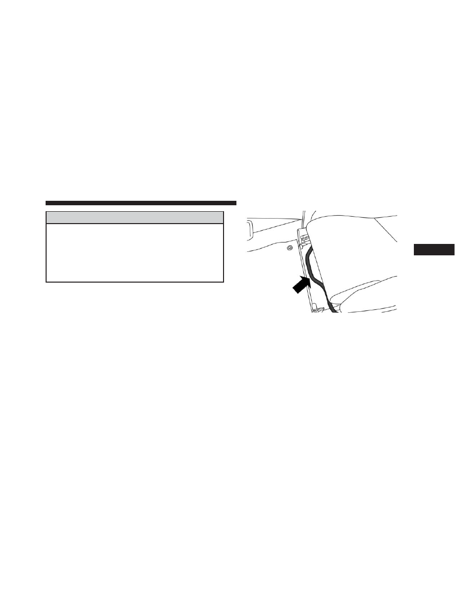
The adjusting bar is at the front of the driver seat, near
the floor. Pull the bar upward to move the seat forward or
rearward. Release the bar once the seat is in the desired
position. Then, using body pressure, move forward and
rearward on the seat to be sure that the seat adjusters
have latched.

Seat Height Adjustment

In order to achieve the ideal driving position, the height
of the seats can also be adjusted. Tools are required to
make this height adjustment. Contact your authorized
dealership.

Seat Adjustment Bar

3

UNDERSTANDING THE FEATURES OF YOUR VEHICLE

79

Recliner Adjustment

The recliner lever is located on the outboard side of the
seat. To recline the seat, lean forward slightly, pull the
recliner lever upward, lean backward until the seat is in
the desired position, and release the lever. To return the
seat to its full upright position, lean forward, pull the
recliner lever upward and hold it until the seat returns to
its full upright position.

Recline Lever

80

UNDERSTANDING THE FEATURES OF YOUR VEHICLE

WARNING!

• Adjusting a seat while driving may be dangerous.

Moving a seat while driving could result in loss of
control which could cause a collision and serious
injury or death.

• Seats should be adjusted before fastening the seat

belts and while the vehicle is parked. Serious
injury or death could result from a poorly adjusted
seat belt.

• Do not ride with the seatback reclined so that the

shoulder belt is no longer resting against your
chest. In a collision you could slide under the seat
belt, which could result in serious injury or death.

Non-Adjustable Head Restraints

The non-adjustable head restraints are form fitted into
the upper structure of the seatback and are designed to
reduce the risk of injury by restricting head movement in
the event of a rear impact. The seatback should be
properly adjusted to an upright position where the head
restraint is positioned as close as possible to the back of
your head.

WARNING!

Be certain that the seatback is locked securely into
position. Otherwise, the seat will not provide the
proper stability for passengers. An improperly
latched seatback could cause serious injury.

3

UNDERSTANDING THE FEATURES OF YOUR VEHICLE

81

TO OPEN AND CLOSE THE DECKLID

CAUTION!

• To prevent possible damage, do not slam the deck-

lid to close it. Use a firm downward push at the
center of the decklid to ensure the decklid latch is
fully engaged.

• During normal car operation, the luggage compart-

ment (located rear of the engine) can reach tem-
peratures above 149 degrees. Do not transport ob-
jects in the luggage compartment that may be
damaged at such temperatures. Do not place aero-
sol cans in the luggage compartment.

To open the decklid:

1. Open the drivers side door.

2. Pull the decklid release lever located on the rear of the

drivers door sill.

Decklid Release Lever

82

UNDERSTANDING THE FEATURES OF YOUR VEHICLE

3. Move to the rear of the vehicle and lift the decklid.

4. Lift upward on the decklid prop rod to release it from

the stowage retainer.

Decklid Lift Point Location

1 — Decklid Prop Rod
2 — Stowage Retainer Location

3

UNDERSTANDING THE FEATURES OF YOUR VEHICLE

83

5. Place the decklid prop rod in the decklid slot to secure

the decklid in the open position.

CAUTION!

To prevent possible damage, do not slam the decklid
to close it. Use a firm downward push at the center of
the decklid to ensure the decklid latch is fully
engaged.

WARNING!

• The maximum load limit for the luggage compart-

ment, in addition to the kits provided, is 33.1 lbs.
(15kg). Do not exceed the maximum permitted load
in the luggage compartment. When accessing the
rear luggage compartment, do not come into con-
tact with engine, or other components, that may be
hot and could burn you if touched.

(Continued)

Decklid Prop Rod Slot

84

UNDERSTANDING THE FEATURES OF YOUR VEHICLE

WARNING! (Continued)

• Access the luggage compartment only with the

vehicle stationary. Before exiting the vehicle, you
should always place the vehicle into First gear,
apply the parking brake, and remove the key from
the ignition. Never leave the key fob in the vehicle
or in a location accessible to children.

• The decklid may drop suddenly, causing serious

injury, if the supporting rod is not positioned
correctly.

• The decklid must always be closed properly, and

the lock engaged, while the vehicle is in motions.

LIGHTS

Multifunction Lever

The multifunction lever, located on the left side of the
steering wheel, controls the operation of the headlights,
headlight beam selection, passing light and turn signals.

NOTE:

The external lights can only be turned on with

the ignition in the ON/RUN position.

Multifunction Lever

3

UNDERSTANDING THE FEATURES OF YOUR VEHICLE

85

Headlights

Rotate the end of the multifunction lever up-
ward to the first detent for headlight operation.

NOTE:

When the headlights are turned on, the Daytime

Running Lights will be deactivated.

Daytime Running Lights

To activate the Daytime Running Lights (DRL), rotate the
end of the multifunction lever to the symbol.

NOTE:

The low beams and side/tail lights will not be on

with DRL.

High Beams

With the low beams activated, pull the multifunc-
tion lever towards the steering wheel to turn on

the high beams. A high beam symbol will illuminate in
the cluster to indicate the high beams are on. Pull the
multifunction lever a second time to switch the head-
lights back to low beam.

Headlight Operation

86

UNDERSTANDING THE FEATURES OF YOUR VEHICLE

Flash-To-Pass

You can signal another vehicle with your headlights by
partially pulling the multifunction lever toward the steer-
ing wheel. This will cause the high beam headlights to
turn on until the lever is released.

Parking Lights

To turn on the parking lights, remove the key
or turn the ignition to OFF/LOCK position and
turn on the headlights.

Turn Signals

Move the multifunction lever up or down and the arrows
on each side of the instrument cluster flash to show
proper operation of the front and rear turn signal lights.

NOTE:

If either light remains on and does not flash, or

there is a very fast flash rate, check for a defective outside
light bulb. If an indicator fails to light when the lever is
moved, it would suggest that the indicator bulb is
defective.

Lane Change Assist

Tap the lever up or down once, without moving beyond
the detent, and the turn signal (right or left) will flash five
times then automatically turn off.

Follow Me Home/Headlight Delay — If Equipped

When this feature is selected the driver can choose to
have the headlights remain on for a preset period of time.

3

UNDERSTANDING THE FEATURES OF YOUR VEHICLE

87

Activation

Remove the key or turn the ignition to the OFF/LOCK
position, and pull the multifunction lever toward the
steering wheel, within two minutes. Each time the lever
is pulled, the activation of the lights will be extended by
30 seconds. The activation of the lights can be extended to
a maximum of 210 seconds.

Deactivation

Pull the multifunction lever toward the steering wheel
and hold it for more than two seconds.

Dimmer Controls

The dimmer controls are located on the left side of the
instrument panel below the instrument cluster.

Pressing the up or down arrow will increase or decrease
the brightness of the instrument panel lights.

Dimmer Controls

88

UNDERSTANDING THE FEATURES OF YOUR VEHICLE

Interior Light

The interior light is located in the headliner in between
the sun visors. The interior light can be set to three
different positions (Off/Left Position, Center Position,
On/Right Position).

Using the interior light lens, press the lens to the right
from its center position and the lights are always on.
Press the lens to the left from its center position and the
lights are always off. Leave the lens in the center position,
and the light is turned on and off when the doors are
opened or closed.

CAUTION!

Before getting out of the vehicle be sure that the
switch is in the center position or that the lights are
off to avoid draining the battery.

Interior Light (Off Position Shown)

3

UNDERSTANDING THE FEATURES OF YOUR VEHICLE

89

Interior Light Timing (Center Position)

There are four different modes of operation that can be
activated in this position:

• When one door is opened a three minute timer is

activated.

• When the key is removed from the ignition (within

two minutes of the ignition being turned off), a 10
second timer is activated.

• When the doors are unlocked with the Key Fob a 10

second timer is activated.

• When the doors are locked with the Key Fob the lights

will turn off.

WINDSHIELD WIPERS AND WASHERS

The windshield wiper/washer controls are located on the
windshield wiper/washer lever on the right side of the
steering column. The front wipers are operated by rotat-
ing a switch, located on the end of the lever.

Windshield Wiper/Washer Lever

90

UNDERSTANDING THE FEATURES OF YOUR VEHICLE

Intermittent Wiper System

Use the intermittent wiper when weather conditions
make a single wiping cycle with a variable pause be-
tween cycles. Rotate the end of the multifunction lever to
the first detent position. There are four possible delay
intervals that depend on the vehicle speed.

Windshield Wiper Operation

Rotate the end of the lever upward, to the first detent past
the intermittent settings for low-speed wiper operation.
Rotate the end of the lever upward to the second detent
past the intermittent settings for high-speed wiper opera-
tion.

Mist

Use the mist feature when weather conditions make
occasional usage of the wipers necessary. Push the lever
upward to the mist position and release for a single
wiping cycle.

NOTE:

The mist feature does not activate the washer

pump; therefore, no washer fluid will be sprayed on the
windshield. The wash function must be used in order to
spray the windshield with washer fluid.

Windshield Washers

To use the washer, pull the lever toward you and hold
while spray is desired. If the lever is pulled while in the
delay range, the wiper will start and continue to operate
for three wipe cycles after the lever is released, and then
resume the intermittent interval previously selected.

If the lever is pulled while in the off position, the wipers
will operate for three wipe cycles and then turn off.

3

UNDERSTANDING THE FEATURES OF YOUR VEHICLE

91

WARNING!

Sudden loss of visibility through the windshield
could lead to a collision. You might not see other
vehicles or other obstacles. To avoid sudden icing of
the windshield during freezing weather, warm the
windshield with defroster before and during wind-
shield washer use.

TILT/TELESCOPING STEERING COLUMN

This feature allows you to tilt the steering column
upward or downward. It also allows you to lengthen or
shorten the steering column. The tilt/telescoping control
handle is located below the steering wheel at the end of
the steering column.

To unlock the steering column, push the lever downward
(toward the floor). To tilt the steering column, move the
steering wheel upward or downward as desired. To
lengthen or shorten the steering column, pull the steering
wheel outward or push it inward as desired. To lock the

Tilt/Telescoping Column Lever

92

UNDERSTANDING THE FEATURES OF YOUR VEHICLE

steering column in position, push the lever upward until
fully engaged.

WARNING!

Do not adjust the steering column while driving.
Adjusting the steering column while driving or driv-
ing with the steering column unlocked, could cause
the driver to lose control of the vehicle. Failure to
follow this warning may result in serious injury or
death.

ELECTRONIC SPEED CONTROL — IF EQUIPPED

When engaged, the Electronic Speed Control takes over
accelerator operations at speeds greater than 18 mph
(30 km/h) up to the maximum speed of 105 mph
(170 km/h).

The Electronic Speed Control Lever is located on the left
side of the steering column.

NOTE:

In order to ensure proper operation, the Electronic

Speed Control system has been designed to shut down if
multiple speed control functions are operated at the same
time. If this occurs, the Electronic Speed Control system can
be reactivated rotating the end of the multifunction lever
(On/Off) and resetting the desired vehicle set speed.

Electronic Speed Control Lever

3

UNDERSTANDING THE FEATURES OF YOUR VEHICLE

93

To Activate

Rotate the end of the multifunction lever to activate the
Electronic Speed Control. The Cruise Indicator Light in
the Electronic Vehicle Information Center (EVIC) will
illuminate. To turn the system off, rotate the end of the
multifunction lever to the “O” position. The Cruise
Indicator Light will turn off. The system should be
turned off when not in use.

WARNING!

Leaving the Electronic Speed Control system on
when not in use is dangerous. You could accidentally
set the system or cause it to go faster than you want.
You could lose control and have an accident. Always
leave the system OFF when you are not using it.

To Set A Desired Speed

Turn the Electronic Speed Control ON. When the vehicle
has reached the desired speed, move the electronic speed
control lever upward SET(+) and release. Release the
accelerator and the vehicle will operate at the selected
speed.

NOTE:

The vehicle should be traveling at a steady speed

and on level ground before moving the electronic speed
control lever upward SET(+).

To Deactivate

A soft tap on the brake pedal, pushing the RESUME/
CANCEL button, or normal brake pressure while slow-
ing the vehicle will deactivate Electronic Speed Control
without erasing the set speed memory. Rotating the end
of the multifunction lever to the “O” position or turning
the ignition switch OFF erases the set speed memory.

94

UNDERSTANDING THE FEATURES OF YOUR VEHICLE


Content   ..  4  5  6  7   ..