Peugeot 405 Haynes (petrol). Manual - part 29


  Index      Manuals     Peugeot 405 Haynes (petrol) 1.4 (1360 cc), 1.6 (1580 cc), 1.8 (1761 cc), 1.9 (1905 cc) and 2.0 (1998 cc). Repair Manual


Search            


Content   ..  27  28  29  30   ..


Peugeot 405 Haynes (petrol). Manual - part 29


42 Remove the screw securing the switch to
the tailgate. Where applicable, recover the
lockwasher (see illustration).
43 Disconnect the wiring plug and withdraw
the switch.
44 Refitting is a reversal of removal.

Map reading light switch

45 The switch is integral with the light, and
cannot be renewed separately.

Electric sunroof switch

46 Carefully prise the blanking plate (fitted
next to the sunroof switch) from the centre
console (see illustration).
47 Reach in through the aperture left by
removal of the blanking plate, then push out
the switch and disconnect the wiring plug
(see illustration).
48 Refitting is a reversal of removal.

5

Bulbs (exterior lights) -
renewal

2

Whenever a bulb is renewed, note the
following points.

a) Disconnect the battery negative lead

before starting work.

b) Remember that, if the light has just been

in use, the bulb may be extremely hot.

c) Always check the bulb contacts and

holder, ensuring that there is clean metal-
to metal contact between the bulb and its
live(s) and earth. Clean off any corrosion
or dirt before fitting a new bulb.

d) Wherever bayonet-type bulbs are fitted

(see Specifications), ensure that the live
contact(s) bear firmly against the bulb
contact.

e) Always ensure the new bulb is of the

correct rating, and that it is completely
clean before fitting it; this applies
particularly to headlight/foglight bulbs
(see below).

Headlight

Working in the engine compartment,
release the clip securing the cover to the rear
of the headlight unit. Withdraw the cover (see
illustration)
.

Disconnect the wiring plug from the rear of
the headlight bulb.
Release the spring clip securing the bulb in
the light unit, then withdraw the bulb (see
illustrations)
.
When handling the new bulb, use a tissue
or clean cloth, to avoid touching the glass
with the fingers; moisture and grease from the
skin can cause blackening and rapid failure of
this type of bulb. If the glass is accidentally
touched, wipe it clean using methylated spirit.
Install the new bulb, ensuring that it locates
correctly in the light unit. Secure the bulb in
position with the spring clip, and reconnect
the wiring plug.
Refit the cover to the rear of the light unit,
and secure with the clip.

Front sidelight

The sidelight bulb is located in the rear of
the headlight housing.

Working in the engine compartment,
release the clip securing the cover to the rear
of the headlight unit.
10 On models up to 1992, pull the bulbholder
from the rear of the headlight unit. On models
from 1993, it will be necessary to twist the
bulbholder through a quarter turn before it can
be removed (see illustration).
11 The bulb is a push-fit in the bulbholder
(see illustration).
12 Refitting is the reverse of the removal
procedure, ensuring that the bulbholder seal
is in good condition.

Front direction indicator

13 Working in the engine compartment,
unhook the indicator light unit retaining spring
from the lug behind the light (see illustration).
14 Pull the light forwards from the wing panel.
15 Twist the bulbholder anti-clockwise to
release it from the light unit (see illustration).

12•6 Body electrical system

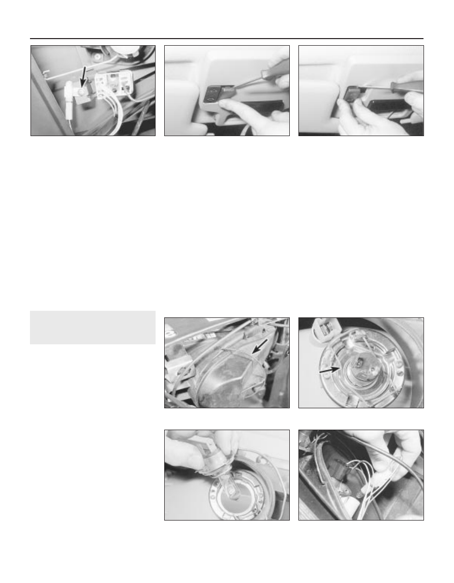
4.42  Luggage compartment courtesy light

switch screw (arrowed) - Estate model

4.47  . . . then prise out the sunroof switch

5.4b  . . . then withdraw the 

headlight bulb

5.4a  Release the spring clip 

(arrowed) . . .

5.2  Headlight rear cover securing clip

(arrowed)

4.46  Prise out the blanking plate . . .

5.10  Pull out the sidelight 

bulbholder . . .

16 The bulb is a bayonet-fit in the bulbholder.
17 Refitting is a reversal of removal, but
ensure that the light unit retaining spring is
correctly engaged.

Front direction 
indicator side repeater

18 Twist the light unit a quarter-turn anti-
clockwise, and carefully pull the unit from the
wing panel, taking care not to damage the
paint.
19 Twist the bulbholder anti-clockwise, and
remove it from the light unit.
20 The bulb is a bayonet-fit in the bulbholder
(see illustration).
21 Refitting is a reversal of the removal
procedure.

Headlight-mounted 
front driving light

22 On certain models, a driving light is
mounted in the headlight unit. The light
operates when the headlights are switched to
main beam.
23 Proceed as described previously in this
Section for the headlight bulb (see illustrations).

Front spoiler-mounted 
driving light/foglight

Note: Some models are fitted with front
foglights which have no securing screws
visible from the front of the lens. At the time of
writing, no information was available for this
type of foglight.
24 Two alternative types of light assembly
may be fitted, depending on model. On some
models, access to the bulb can be obtained

from the behind the spoiler. On other models,
the light unit must be removed for access to
the bulb.
25 On models where the light unit can be
reached from behind the spoiler, reach up

behind the spoiler and disconnect the wiring
from the light. Prise the rubber cover from the
light, then release the spring clip and
withdraw the bulb.
26 On models where the rear of the light unit
is covered by the spoiler, remove the two
securing screws from the front of the light unit
and withdraw the reflector/lens assembly.
Disconnect the wiring from the bulb, then
release the spring clip and withdraw the bulb.
27 When handling the new bulb, use a tissue
or clean cloth, to avoid touching the glass
with the fingers; moisture and grease from the
skin can cause blackening and rapid failure of
this type of bulb. If the glass is accidentally
touched, wipe it clean using methylated spirit.
28 Refitting is the reverse of the removal
procedure, ensuring that the bulb locates
correctly in its housing.

Rear light cluster

Saloon models

29 Open the boot lid.
30 Squeeze the two retaining clips, and
withdraw the bulbholder from the rear of the
light unit (see illustration).
31 The bulbs are a bayonet-fit in the
bulbholder 

(see illustration).

32 Fit the new bulb using a reversal of the
removal procedure.

Estate models

33 The stop/tail lights and the direction
indicator lights are located in the rear wing
panels. The remaining rear lights are located
in the tailgate.

Body electrical system  12•7

5.15  Withdrawing the bulbholder from the

front direction indicator light

5.23b  Removing a headlight-mounted

driving light bulb

5.23a  Headlight-mounted driving light bulb

securing clip (arrowed)

5.20  Removing the bulbholder from the

front direction indicator side repeater light

5.13  Front direction indicator light

retaining spring (arrowed)

5.11  . . . and withdraw the bulb

12

5.30  Removing a rear light cluster

bulbholder - Saloon model

5.31  The bulbs are a bayonet-fit in the

bulbholder

34 Open the tailgate.
35 Turn the retaining clip and open the light
unit cover flap.
36 Squeeze the two retaining clips, and
withdraw the bulbholder from the rear of the
light unit (see illustrations).
37 The bulbs are a bayonet-fit in the
bulbholder.
38 Fit the new bulb using a reversal of the
removal procedure.

Number plate light

Saloon models

39 Prise the lens from the underside of the
bumper for access to the bulb (see
illustration)
.
40 The bulb is a bayonet-fit in the bulbholder
(see illustration).
41 Fit the new bulb using a reversal of the
removal procedure.

Estate models

42 Carefully prise the light unit from the
tailgate (see illustration).
43 Unclip the bulbholder from the lens
assembly (see illustration).
44 The bulb is a bayonet-fit in the bulbholder.
45 Fit the new bulb using a reversal of the
removal procedure.

6

Bulbs (interior lights) -
renewal

2

General

Refer to Section 5, paragraph 1.

Courtesy light, glovebox and
luggage compartment lights

Carefully prise the lens from the light unit.

Note that in some cases, it may prove
necessary to prise out the complete light unit
to enable the lens to be removed (see
illustrations)
.
The bulb is a push-fit in the holder.
Refitting is a reversal of removal.

Map reading light

Prise the map reading light from the roof
console.
The festoon-type bulb is held between the
spring contacts (see illustration).
Refitting is a reversal of removal.

Heater/ventilation 
control unit illumination bulbs

Models up to 1992

For access to the bulbs, the control unit
must be removed as described in Chapter 11,
but note that there is no need to disconnect
the control cables from the unit. Once the

12•8 Body electrical system

5.36a  Removing a rear wing-mounted light

bulbholder - Estate model

5.39  Prise the lens from the bumper . . .

5.43  . . . and unclip the bulbholder from

the lens - Estate model

5.42  Prise out the number plate 

light unit . . .

5.40  . . . and withdraw the number plate

light bulb - Saloon model

5.36b  Removing a tailgate-mounted light

bulbholder - Estate model

6.2a  Prising out a courtesy light

6.2b  Prise off the lens for access 

to the bulb

6.6  Map reading light removed 

for access to bulb

securing screws have been removed, the
control unit can be pulled forwards sufficiently
for access to the bulbs without disconnecting
the cables.

Models from 1993

Disconnect the battery negative lead.
10 Remove the centre console as described
in Chapter 11, Section 29.
11 Unscrew the two screws located at the
bottom of the ashtray housing.
12 Where applicable, remove the radio/
cassette player as described in Section 20.
On models not fitted with a radio/cassette
player, prise out the oddments tray.
13 Remove the two securing screws from the
top of the radio/cassette player/oddments
tray housing, then withdraw the housing from
the facia. Where applicable, disconnect the
wiring plug(s) from the rear of the panel.
14 Prise the blanking plate from the top
corner of the facia centre ventilation nozzle
housing. Remove the now-exposed securing
screw.
15 Remove the four housing securing screws
located under the heater control panel. Two
screws are accessible from the front of the
housing, and two screws from underneath.
16 Carefully prise the switches from below
the centre facia ventilation nozzles to reveal
the remaining housing securing screw.
Remove the screw.
17 Pull the housing forwards, and disconnect
the wiring from the clock, then withdraw the
housing.
18 Carefully pull the knobs from the heater
control levers.

19 Unclip the front panel from the heater
control unit to expose the bulbs (see
illustration)
.
20 The bulbs are a push-fit in the bulbholders
(see Haynes Hint).
21 Refitting is a reversal of removal.

Clock illumination bulb

22 For access to the clock illumination bulb,
remove the clock as described in Section 11.
Note that on models from 1993, access to the
bulb can be gained once the housing has
been removed from the facia - there is no
need to remove the clock from the housing.
23 To remove the bulbholder, twist it anti-
clockwise  (see illustration). The bulb is
integral with the bulbholder.
24 Fit the new bulb using a reversal of the
removal procedure.

Facia switch illumination bulbs

25 The bulbs are integral with the switches,
and cannot be renewed independently.

Instrument panel illumination
and warning light bulbs

26 Remove the instrument panel as
described in Section 9.
27 Twist the relevant bulbholder anti-
clockwise to remove it from the rear of the
panel (see illustration).
28 The bulbs are a push-fit in the
bulbholders.
29 On completion, refit the instrument panel
with reference to Section 9.

7

Exterior light units 
removal and refitting

2

Note: Disconnect the battery negative lead
before removing any light unit, and reconnect
the lead after refitting the unit.

Headlight

Removal

Working in the engine compartment,
release the clip securing the cover to the rear
of the headlight unit.
Disconnect the wiring plugs from the bulbs
located in the headlight unit.
Remove the direction indicator light as
described during the bulb renewal procedure
in Section 5.
On models with cable-operated headlight
adjusters, disconnect the adjuster from the
headlight as follows.

a) Tun the adjuster and pull it from the

bracket on the body front panel.

b) Carefully pull the balljoint from the socket

in the rear of the headlight (see
illustration)
.

On models with electrically-operated
headlight adjusters, disconnect the wiring
plug from the adjuster in the rear of the
headlight.
Remove the radiator grille panel as
described in Chapter 11.
Carefully prise the lower trim plate from the
bottom of the headlight (see illustration).

Body electrical system  12•9

6.23  Removing the clock illumination bulb

- models from 1993

7.7  Removing the trim plate from the

bottom of the headlight

7.4  Removing a cable-operated 

headlight adjuster

6.27  Removing an instrument panel

illumination bulb

6.19  Unclip the front panel from 

the heater control unit

12

A length of rubber tubing can be used
to remove and refit the bulbs

Unscrew the two outer headlight securing
bolts, and pull the unit forwards from the body
panel (see illustration).
If desired, the headlight lens can be
renewed by prising off the metal securing
clips and withdrawing the lens from the front
of the light unit (see illustration).
10 Before fitting a new lens, ensure that the
seal located in the groove around the front of
the headlight is in good condition, and renew
if necessary.

Refitting

11 Refitting is a reversal of removal, but on
completion have the headlight beam
alignment checked at the earliest opportunity.

Front direction indicator

12 The procedure is described as part of the
bulb renewal procedure in Section 5.

Front direction 
indicator side repeater

13 The procedure is described as part of the
bulb renewal procedure in Section 5.

Front spoiler-mounted 
driving light/foglight

14 Two alternative types of light assembly
may be fitted, depending on model. The light
may be mounted either directly in the front
spoiler, or in a cowl screwed to the front
spoiler.

Cowl-mounted light

15 Reach up behind the spoiler, and
disconnect the wiring from the light.

16 Remove the two screws securing the light
cowl to the spoiler, then withdraw the
cowl/light assembly rearwards from the
bumper 

(see illustration).

17 The light unit can be removed from the
cowl after unscrewing the knurled securing
nut at the rear of the unit (see illustration).
18 Refitting is a reversal of removal, but on
completion, check and if necessary adjust the
light beam alignment. Adjustment can be
made using the knurled nuts at the rear of the
unit.

Light mounted directly in spoiler

Note: Some models are fitted with front
foglights which have no securing screws
visible from the front of the lens. At the time of
writing, no information was available for this
type of foglight.
19 To improve access, jack up the front of
the vehicle and support securely on axle
stands (see “Jacking and Vehicle Support”).
20 Trace the wiring back from the rear of the
foglight, and disconnect the wiring connector.
21 Slacken and remove the foglight securing
nut, and withdraw the light unit from the
spoiler. Recover any washers and spacers,
noting their locations to ensure correct
refitting.
22 Refitting is a reversal of removal, ensuring
that any washers and spacers on the securing
stud are positioned as noted before removal.

Rear light cluster

Saloon models

23 Open the boot lid.

24 Squeeze the two retaining clips, and
withdraw the bulbholder from the rear of the
light unit.
25 Disconnect the wiring plug from the
bulbholder.
26 Pull up the luggage compartment weather-
strip, and release the luggage compartment
inner trim panel from the rear panel to expose
the light unit securing nuts.
27 Unscrew the securing nuts, then withdraw
the unit from outside the vehicle. Withdraw
the outboard side of the unit first, then
disengage the inboard edge from the body
(see illustrations).
28 Refitting is a reversal of removal

Estate models

29 The stop/tail lights and the direction
indicator lights are located in the rear wing
panels. The remaining rear lights are located
in the tailgate.
30 Open the tailgate.
31 Turn the retaining clip and open the light
unit cover flap.
32 Squeeze the two retaining clips, and
withdraw the bulbholder from the rear of the
light unit.
33 Disconnect the wiring plug from the
bulbholder.
34 Unscrew the securing nuts and withdraw
the light unit from outside the vehicle (see
illustrations)
.
35 Refitting is a reversal of removal.

Number plate light

Saloon models

36 Remove the two securing screws, then

12•10 Body electrical system

7.8  Outer headlight securing bolts

(arrowed)

7.16  Remove the front driving light/

foglight cowl securing screws

7.27b  . . . then withdraw the rear light unit

- Saloon model

7.27a  Unscrew the securing nuts

(arrowed) . . .

7.17  Unscrew the nut (arrowed) to

separate the light from the cowl

7.9  Removing a headlight lens 

securing clip

withdraw the light unit from the bumper and
disconnect the wiring plug (see illustration).
37 Refitting is a reversal of removal.

Estate models

38 Carefully prise the unit from the tailgate
and disconnect the wiring plug.
39 Refitting is a reversal of removal.

8

Headlight beam alignment -
general information and
component renewal

Accurate adjustment of the headlight beam
is only possible using optical beam-setting
equipment, and this work should therefore be
carried out by a Peugeot dealer or suitably-
equipped workshop.
For reference, the headlights can be finely
adjusted using a suitable-sized Allen key to
rotate the adjuster assemblies fitted to the

rear of each light unit. The outer adjuster
alters the vertical height of the beam, whilst
the inner adjuster alters the horizontal position
of the beam (see illustrations). Prior to
adjustment, ensure the vehicle is unladen, and
that the adjuster units (see below) are both set
to position “0”, or “1”, as applicable.
Each headlight unit is equipped with a
three- or four-position vertical beam adjuster
unit (depending on model) - this can be used
to adjust the headlight beam, to compensate
for the relevant load which the vehicle is
carrying. The adjuster units may be
incorporated into the vertical beam adjuster
on the back of the headlight, or on certain
models, an adjuster switch is provided on the
facia. On models with adjusters mounted on
the headlights, access to them can be gained
with the bonnet open. The adjusters should
be positioned as follows according type, and
the load being carried in the vehicle.

Headlight-mounted adjusters -
models up to 1992

Position 1

No load

Position 2

Medium load

Position 3

Maximum load

Headlight-mounted adjusters -
models from 1993

Position 1

Front seat occupied

Position 2

All seats occupied and 
luggage compartment full

Position 3

Driver’s seat occupied and
luggage compartment full

Facia-mounted adjuster 

Position 0

Front seats occupied

Position 1

All seats occupied

Position 2

All seats occupied and 
luggage compartment full

Position 3

Driver’s seat occupied and
luggage compartment full

Where applicable, ensure both adjusters
are set to the same position, and be sure to
reset if the vehicle load is altered.

Component renewal

Mechanical remote adjuster
mechanism

Working beneath the facia ventilation
nozzles, prise out the three blanking plates
covering the instrument panel visor screws.
Remove the screws, and lift off the
instrument panel visor.
Move the steering column to its lowest
position.
Carefully prise off the headlight adjuster
switch knob.
Remove the securing screws, and withdraw
the driver’s side upper facia panel. Disconnect
the wiring from the switches in the panel as the
panel is removed.
10 Remove the two screws securing the
adjuster switch to the facia (see illustration).
11 Working in the engine compartment, turn
and pull the adjusters from the brackets
behind the headlights. The ends of the
adjusters are a push-fit (balljoints) in the rear
of the headlights.
12 Unclip the adjuster cables from the
brackets and clips in the engine bay. Feed the
switch cable through the bulkhead into the
engine bay (see Haynes Hint overleaf).

Body electrical system  12•11

7.34c  Tailgate-mounted rear light cluster

securing nuts (arrowed) - Estate model

8.2b  Headlight beam horizontal fine

adjuster (arrowed)

8.2a  Headlight beam vertical height fine

adjuster (A) and adjuster unit knob (B)

7.36  Number plate light securing screws

(arrowed) - Saloon model

7.34b  Withdrawing a rear wing-mounted

light cluster - Estate model

7.34a  Rear wing-mounted light cluster

securing nuts (arrowed) - Estate model

12

8.10  Headlight adjuster switch 

securing screws (arrowed)

13 Refitting is a reversal of removal. Where
applicable, use the string to pull the cable into
position through the bulkhead into the
passenger compartment.

Electric adjuster switch

14 Refer to Section 4.

Electric adjuster unit

15 Disconnect the battery negative lead.
16 Working at the rear of the headlight,
disconnect the wiring plug from the adjuster
unit (mounted in the rear of the headlight).
17 Twist the adjuster unit (or the locking
collar, as applicable) to release the adjuster
from the aperture in the headlight unit.

9

Instrument panel 
removal and refitting

2

Models up to 1992

Removal

Disconnect the battery negative lead.
Working beneath the facia ventilation
nozzles, prise out the three blanking plates
covering the instrument panel visor securing
screws (see illustration).
Remove the screws, and lift off the
instrument panel visor (see illustrations).
Move the steering column to its lowest
position.
Where applicable, carefully prise off the
headlight adjuster switch knob (see illustration).
Remove the securing screws, and withdraw
the driver’s side upper facia panel (see
illustration)
. Disconnect the wiring from the
switches in the panel as the panel is removed.
Unclip the trim panel from the lower edge of
the instrument panel to expose the upper
centre facia panel securing screw. Remove
the screw (see illustration).
Remove the instrument panel screws from
the top corners of the panel (see illustration).

Tilt the instrument panel forwards, and
disconnect the speedometer cable from the
rear of the panel. Give the cable end fitting a
sharp tug to free it from the speedometer.
10 Disconnect the wiring plugs from the rear
of the instrument panel, noting their locations
to ensure correct refitting.
11 Lift the instrument panel from the facia.

Refitting

12 Refitting is a reversal of removal, but
ensure that the wiring plugs are correctly
reconnected, and make sure that the cable is
securely reconnected to the speedometer,
before securing the instrument panel in
position in the facia.

Models from 1993

Removal

13 Disconnect the battery negative lead.
14 Release the securing clips, and remove

the lower trim panel from the driver’s footwell.
15 Where applicable, move the steering
column adjuster lever to the released position.
16 Working under the steering column
loosen, but do not remove, the lower steering
column securing bolts (note that on some
models, it will be necessary to remove the
steering column shrouds for access to the
steering column securing bolts - see Chapter
11).
17 Similarly, unscrew and remove the two
upper steering column securing nuts.
18 Cover the upper steering column shroud
with cloth to protect it during the following
procedure.
19 Working under the instrument panel, prise
the ends of the trim panel upwards to release
it from the facia, and withdraw the panel (see
illustration)
. If necessary, unscrew the lower
steering column fixings further to enable the
column to be lowered sufficiently for access.

9.8  Instrument panel securing screw

(arrowed)

12•12 Body electrical system

9.2  Prise out the blanking plates . . .

9.3b  Instrument panel visor securing

screw locations (arrowed)

9.7  Remove the upper centre facia panel

securing screw

9.6  Withdrawing the driver’s side 

upper facia panel

9.5  Prise off the headlight adjuster 

switch knob

9.3a  . . . and remove the visor 

securing screws

Tie a length of string to the
end of the adjuster cable
before pulling it through the
bulkhead. Untie the string

and leave it in position to aid refitting.

20 Working in the engine compartment,
locate the speedometer cable ball, which
rests in a grommet in the engine compartment
bulkhead, then pull the ball sharply to release
the cable from the speedometer.
21 Unscrew the two lower and single upper
instrument panel securing screws (see
illustration)
.
22 Insert a soft plastic or wooden lever
between the top instrument panel securing
clip (the upper securing screw location) and
the facia, and carefully lever the clip down
until the instrument panel can be withdrawn
forwards (see illustration).
23 Disconnect the wiring plugs from the rear
of the panel, and withdraw the panel from the
facia (see illustration).

Refitting

24 Refitting is a reversal of removal, bearing
in mind the following points.

a) Before refitting, ensure that the Velcro

strip, which retains the wiring looms, is in
position at the top of the instrument panel
aperture.

b) Reconnect the speedometer cable by

pushing the cable ball into position in the
bulkhead grommet.

c) Tighten the steering column securing nuts

to the specified torque.

10 Instrument panel

components 
removal and refitting

3

General

Remove the instrument panel as described
in Section 9,  then proceed as described
under the relevant sub-heading.

Gauges - models up to 1992

Release the securing clips, and unscrew
the three securing screws, then remove the
panel surround/lens assembly from the
instrument panel.
Unscrew the relevant securing screws or
nuts, then withdraw the gauge from the front
of the panel.
Refitting is a reversal of removal.

Gauges - models from 1993

Working at the rear of the panel, remove the
lens securing screws from around the edge of
the panel (see illustration).
Remove the two recessed lens securing
screws from the rear of the panel (see
illustration)
.
Release the securing clips by carefully
prising with a screwdriver, then withdraw the
lens assembly.
Where necessary, for access to the gauge
fixings at the rear of the gauge, remove the
screws and withdraw the cover from the rear
of the instrument panel (see illustration).
Unscrew the nuts from the gauge contact
studs, or remove the gauge securing screws,
as applicable (see illustration).
10 Where applicable, working at the front of
the gauge, remove the gauge securing screws
(see illustration).

Body electrical system  12•13

9.22  Lever the upper securing 

clip down . . .

10.6  Remove the two recessed lens

securing screws

10.5  Two of the instrument panel lens

securing screws (arrowed)

9.23  . . . until the instrument panel can be

withdrawn

9.21  Unscrew the lower instrument panel

securing screws

9.19  Prise the trim panel from the facia

12

Coat the ball with soapy
water to aid refitting.

10.8  Removing the cover from the rear of

the instrument panel

10.9  Fuel gauge securing nuts (arrowed)


Content   ..  27  28  29  30   ..