Peugeot 405 Haynes (petrol). Manual - part 28


  Index      Manuals     Peugeot 405 Haynes (petrol) 1.4 (1360 cc), 1.6 (1580 cc), 1.8 (1761 cc), 1.9 (1905 cc) and 2.0 (1998 cc). Repair Manual


Search            


Content   ..  26  27  28  29   ..


Peugeot 405 Haynes (petrol). Manual - part 28


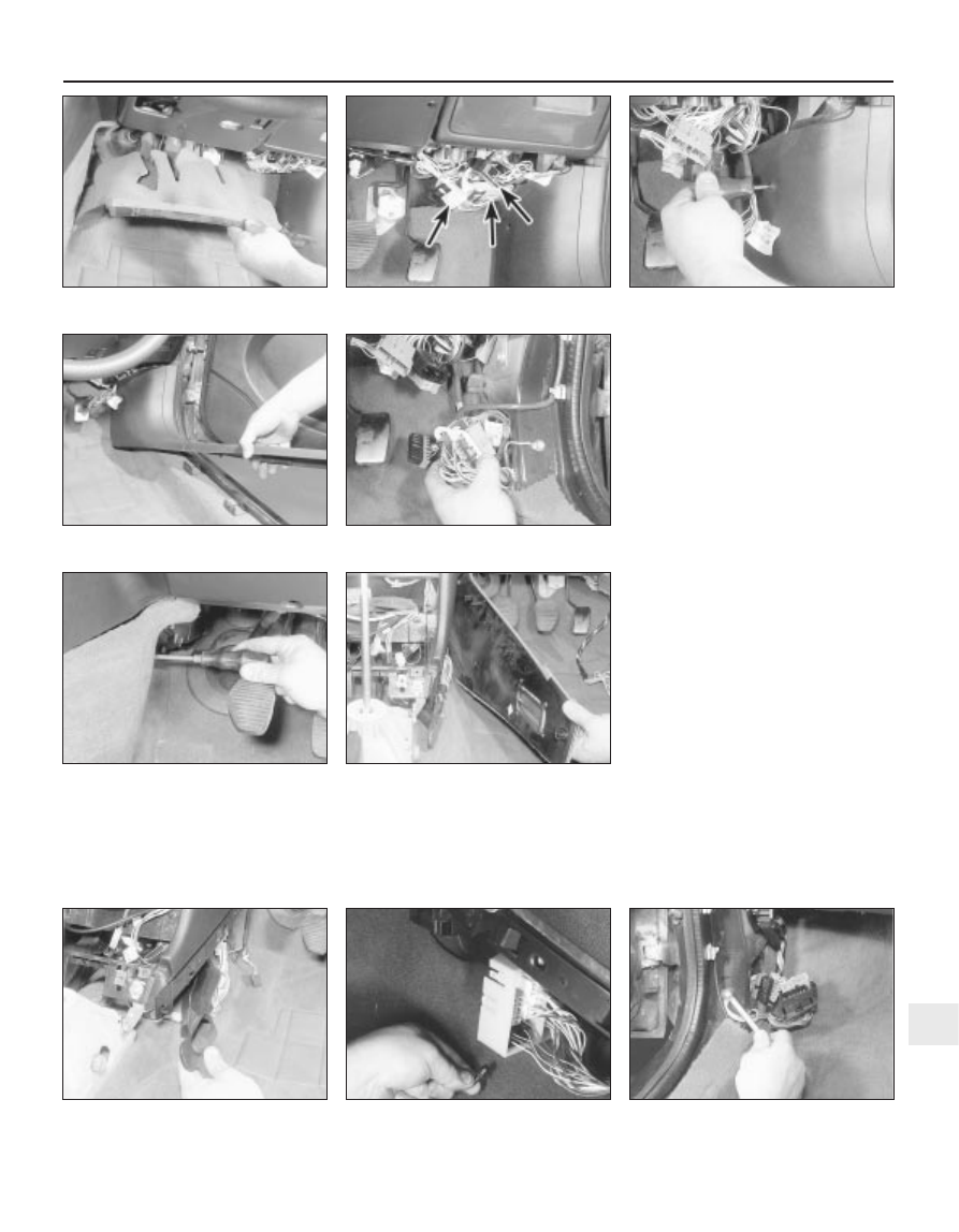
three wiring connectors (see illustrations).
Where applicable, release the wiring
harnesses from the clips on the facia.
42 Remove the securing screw, then pull up
the driver’s footwell side trim panel to release
the securing clips. Remove the panel, to

expose the wiring connector bracket (see
illustrations)
.
43 Release the two securing clips, and pull
the wiring connector bracket from the
footwell. Disconnect the connectors from the
bracket (see illustration).

44 Where applicable (if the earth cable
connects to the facia wiring harness), unbolt
the earth cable from the footwell, then release
the wiring harness from the clips under the
facia.
45 Working at the centre of the facia, remove
the securing screws, and withdraw the facia
centre side trim panels, to expose the heater
air ducts (see illustrations).
46 Where applicable remove the screws, and
withdraw the air ducts (see illustration).
47 Cut the cable-tie securing the wiring
harness to the bracket at the centre of the
driver’s side facia.
48 Release the plastic clips securing the
large connector block to the bracket on the
driver’s side of the centre facia, then release
the connectors from the connector block, and
separate the two halves of each connector
(see illustration).
49 Similarly, working at the passenger’s side
of the centre facia, remove the plastic clips
securing the connector block to the bracket
on the floor and to the heater assembly.
50 Working in the passenger’s footwell,
release the securing clips, and remove the
carpet trim panel from under the facia.
51 Remove the securing screw, then pull up
the passenger’s footwell side trim panel to
release the securing clips. Remove the panel,
to expose the wiring connector block. Release
the connector block from the footwell, and
separate the two halves of each wiring
connector.
52 Unbolt the earth lead from the passenger
footwell, then release the wiring harnesses
from any clips in the footwell (see illustration).

Bodywork and fittings  11•23

30.42a  Remove the securing screw . . .

30.45a  Remove the securing screws . . .

30.43  Pull the connector bracket 

from the footwell

30.42b  . . . then remove the footwell 

side trim panel

30.41b  . . . then disconnect the three

wiring connectors (arrowed)

30.41a  Remove the carpet trim panel . . .

11

30.45b  . . . and withdraw the facia centre

side trim panels

30.46  Withdrawing an air duct

30.48  Release the connector block from

the bracket on the driver’s side of the facia

30.52  Unbolt the earth lead from the

passenger’s footwell

53 Remove the securing screw, and
withdraw the bonnet release lever from the
side of the footwell (see illustration).
54 Remove the steering column shrouds as
described in Section 28, but note that, where
applicable, there is no need to disconnect the
wiring from the radio/cassette player remote
control switch - feed the switch wiring up
through the facia (the wiring should have been
disconnected from the rear of the
radio/cassette player), and withdraw the
wiring complete with the lower shroud.
55 Remove the steering column as described
in Chapter 10.
56 Remove the two securing screws, and
withdraw the wiring connector/control unit
bracket from the left-hand side of the steering
column bracket (see illustration).
57 Where applicable, similarly remove the
wiring connector bracket from the right-hand
side of the steering column bracket.

58 Remove the instrument panel as
described in Chapter 12.
59 Working in the driver’s footwell,
disconnect the wiring plug from the stop light
switch, then release the switch wiring harness
from the clips under the facia.
60 Unplug the main wiring harness
connectors, from the connector block
mounted under the driver’s side of the  facia
(see illustration). To improve access to the
wiring connectors, the connector block can
be lowered from the facia by removing the
two front bolts securing the bracket to the
facia, and the rear nut securing the bracket to
the stud on the bulkhead.
61 On left-hand-drive models, remove the
screw securing the wiring bracket to the
driver’s side of the bulkhead, next to the
clutch pedal.
62 Where applicable, pull the relay out of its
connector at the rear of the steering column

bracket, then pull the connector out of the
bracket (see illustrations).
62 Remove the heater control unit as
described in Chapter 3.
63 Working in the engine compartment,
remove the scuttle grille panel (Section 25).
64 Remove the securing clip, and withdraw
the plastic shield from the passenger’s side of
the scuttle (see illustrations).
65 On left-hand-drive models, working in the
scuttle, remove the heater inlet duct grille, and
move the connector block/electronic control
unit housing to one side for access to the
facia securing nuts.
66 Working inside the vehicle, unscrew the
two bolts securing the facia side brackets to
the footwells (one bolt in each footwell) (see
illustration)
.
67 Similarly, unscrew the two centre facia
lower securing bolts, one on each side of the
facia centre section (see illustration).

30.67  Unscrew the centre facia lower

securing bolts

30.66  Unscrew the bolts securing the 

facia brackets to the footwells

30.64b  . . . and withdraw the shield 

from the scuttle

11•24 Bodywork and fittings

30.53  Remove the screw and withdraw the

bonnet release lever

30.60  Unplug the main wiring harness

connectors

30.64a  Remove the securing clip . . .

30.62b  . . . then pull the connector from

the steering column bracket

30.62a  Pull the relay out of 

its connector . . .

30.56  Remove the securing screws and

withdraw connector/control unit brackets

68 Unscrew the centre facia upper securing
bolt, located above the heater control unit
(see illustration).
69 Unscrew the two rear centre facia
securing bolts, securing the facia brackets to
the heater assembly (see illustration).
70 Working in the engine compartment,
unscrew the three facia securing nuts located
in the scuttle (see illustration).
71 Make a final check to ensure that all
relevant wiring harnesses have been
unclipped and released from the facia
assembly then, with the aid of an assistant,
pull the facia back from the bulkhead. Note
the location and routing of all wiring
harnesses, particularly note the location of the
Velcro fixings.
72 Release the speedometer cable sleeve
from the instrument panel housing in the facia,
then manipulate the facia assembly out
through one of the door apertures (see
illustration)
.

Refitting

73 Refitting is a reversal of removal, bearing
in mind the following points.

a) Reconnect the wiring plugs to the large

connector block on the driver’s side of the
facia before refitting the facia fixings, and
bolting the connector block in position.

b) Check that the air ducts are correctly

located and engaged with their relevant
vents. Access to the passenger’s side air
duct can be improved by removing the
glovebox (see Section 28).

c) Ensure that all wiring harnesses are

correctly located and routed as noted
before removal, and ensure that the
Velcro fixings are in position, where
applicable.

d) Refit the heater control unit (Chapter 3).

e) Refit the instrument panel with reference

to Chapter 12.

f) Refit the steering column (Chapter 10).
g) Refit the centre console with reference to

Section 29.

Bodywork and fittings  11•25

30.70  Facia securing nut (arrowed) in

scuttle

30.69  . . . and the rear centre facia

securing bolts

30.68  Unscrew the centre facia upper

securing bolt . . .

11

30.72  Release the speedometer cable

sleeve from the facia

12

General

System type  . . . . . . . . . . . . . . . . . . . . . . . . . . . . . . . . . . . . . . . . . . . . . .

12-volt negative earth

Fuses

 . . . . . . . . . . . . . . . . . . . . . . . . . . . . . . . . . . . . . . . . . . . . . . . . .

see Wiring Diagrams

Bulbs

Type

Wattage

Headlights:

Dip/main beam  . . . . . . . . . . . . . . . . . . . . . . . . . . . . . . . . . . . . . . . . . .

H4

60/55

Driving light  . . . . . . . . . . . . . . . . . . . . . . . . . . . . . . . . . . . . . . . . . . . . .

H1

55

Front foglight/spoiler-mounted driving light  . . . . . . . . . . . . . . . . . . . . . .

H3

55

Front sidelights  . . . . . . . . . . . . . . . . . . . . . . . . . . . . . . . . . . . . . . . . . . . .

Push-fit

5

Direction indicator light . . . . . . . . . . . . . . . . . . . . . . . . . . . . . . . . . . . . . .

Bayonet

21

Direction indicator side repeater  . . . . . . . . . . . . . . . . . . . . . . . . . . . . . .

Bayonet

5

Stop/tail light . . . . . . . . . . . . . . . . . . . . . . . . . . . . . . . . . . . . . . . . . . . . . .

Bayonet

21/5

Rear tail light  . . . . . . . . . . . . . . . . . . . . . . . . . . . . . . . . . . . . . . . . . . . . . .

Bayonet

5

Rear foglight  . . . . . . . . . . . . . . . . . . . . . . . . . . . . . . . . . . . . . . . . . . . . . .

Bayonet

21

Reversing light  . . . . . . . . . . . . . . . . . . . . . . . . . . . . . . . . . . . . . . . . . . . .

Bayonet

21

Number plate light  . . . . . . . . . . . . . . . . . . . . . . . . . . . . . . . . . . . . . . . . .

Push-fit

5

Torque wrench setting

Nm

lbf ft

Air bag unit securing screws  . . . . . . . . . . . . . . . . . . . . . . . . . . . . . . . . .

8

6

Chapter 12
Body electrical system

Air bag system - general information, precautions and system

de-activation  . . . . . . . . . . . . . . . . . . . . . . . . . . . . . . . . . . . . . . . . . .24

Air bag system components - removal and refitting  . . . . . . . . . . . . .25
Anti-theft alarm system - general information  . . . . . . . . . . . . . . . . . .23
Bulbs (exterior lights) - renewal  . . . . . . . . . . . . . . . . . . . . . . . . . . . . . .5
Bulbs (interior lights) - renewal  . . . . . . . . . . . . . . . . . . . . . . . . . . . . . . .6
Cigarette lighter - removal and refitting  . . . . . . . . . . . . . . . . . . . . . . .12
Clock - removal and refitting  . . . . . . . . . . . . . . . . . . . . . . . . . . . . . . .11
Electrical fault finding - general information  . . . . . . . . . . . . . . . . . . . . .2
Electrical system check  . . . . . . . . . . . . . . . . . . . .See “Weekly checks”
Exterior light units - removal and refitting . . . . . . . . . . . . . . . . . . . . . . .7
Fuses and relays - general information  . . . . . . . . . . . . . . . . . . . . . . . .3
General information and precautions  . . . . . . . . . . . . . . . . . . . . . . . . . .1
Headlight beam alignment - general information and 

component renewal  . . . . . . . . . . . . . . . . . . . . . . . . . . . . . . . . . . . . .8

Horn - removal and refitting  . . . . . . . . . . . . . . . . . . . . . . . . . . . . . . . .14

Instrument panel - removal and refitting  . . . . . . . . . . . . . . . . . . . . . . .9
Instrument panel components - removal and refitting  . . . . . . . . . . . .10
“Lights-on” warning system - general information  . . . . . . . . . . . . . . .13
Loudspeakers - removal and refitting . . . . . . . . . . . . . . . . . . . . . . . . .21
Radio aerial - removal and refitting  . . . . . . . . . . . . . . . . . . . . . . . . . .22
Radio/cassette player - removal and refitting . . . . . . . . . . . . . . . . . . .20
Speedometer cable - removal and refitting  . . . . . . . . . . . . . . . . . . . .15
Switches - removal and refitting  . . . . . . . . . . . . . . . . . . . . . . . . . . . . . .4
Tailgate wiper motor - removal and refitting . . . . . . . . . . . . . . . . . . . .18
Washer fluid level check . . . . . . . . . . . . . . . . . . . .See “Weekly checks”
Windscreen/tailgate/headlight washer system components - 

removal and refitting  . . . . . . . . . . . . . . . . . . . . . . . . . . . . . . . . . . . .19

Windscreen wiper motor and linkage - removal and refitting . . . . . . .17
Wiper arm - removal and refitting  . . . . . . . . . . . . . . . . . . . . . . . . . . . .16
Wiper blade checking and renewal  . . . . . . . . . . .See “Weekly checks”

12•1

Specifications

Contents

Easy, suitable for
novice with little
experience

Fairly easy, suitable
for beginner with
some experience

Fairly difficult,
suitable for competent
DIY mechanic

Difficult, suitable for
experienced  DIY
mechanic

Very difficult,
suitable for expert DIY
or  professional

Degrees of difficulty

5

4

3

2

1

1

General information and
precautions

The electrical system is of 12-volt negative

earth type. Power for the lights and all
electrical accessories is supplied by a
lead/acid type battery, which is charged by
the alternator.

This Chapter covers repair and service

procedures for the various electrical
components not associated with the engine.
Information on the battery, alternator and
starter motor can be found in Chapter 5.

It should be noted that, prior to working on

any component in the electrical system, the
battery negative terminal should first be
disconnected, to prevent the possibility of
electrical short-circuits and/or fires.
Caution: If the radio/cassette player fitted
has an anti-theft security code, (the
standard unit has), refer to the precaution
in the Reference section of this manual
before disconnecting the battery.

Warning: Before carrying out
any work on the electrical
system, read the precautions in
“Safety first!” at the beginning
of this manual, and in Chapter 5.

2

Electrical fault finding -
general information

Note: Refer to the precautions given in
“Safety first!” and in Section 1 of this Chapter
before starting work. The following tests relate
to testing of the main electrical circuits, and
should not be used to test delicate electronic
circuits (such as anti-lock braking systems),
particularly where an electronic control
module is used.

General

A typical electrical circuit consists of an
electrical component, any switches, relays,
motors, fuses, fusible links or circuit breakers
related to that component, and the wiring and
connectors which link the component to both
the battery and the chassis. To help to
pinpoint a problem in an electrical circuit,
wiring diagrams are included after this
chapter.
Before attempting to diagnose an electrical
fault, first study the appropriate wiring
diagram, to obtain a more complete
understanding of the components included in
the particular circuit concerned. The possible
sources of a fault can be narrowed down by
noting whether other components related to
the circuit are operating properly. If several
components or circuits fail at one time, the
problem is likely to be related to a shared fuse
or earth connection.
Electrical problems usually stem from
simple causes, such as loose or corroded
connections, a faulty earth connection, a
blown fuse, a melted fusible link, or a faulty
relay (refer to Section 3 for details of testing
relays). Visually inspect the condition of all
fuses, wires and connections in a problem
circuit before testing the components. Use
the wiring diagrams to determine which
terminal connections will need to be checked,
in order to pinpoint the trouble-spot.
The basic tools required for electrical fault-
finding include a circuit tester or voltmeter (a
12-volt bulb with a set of test leads can also
be used for certain tests); a self-powered test
light (sometimes known as a continuity tester);
an ohmmeter (to measure resistance); a
battery and set of test leads; and a jumper
wire, preferably with a circuit breaker or fuse
incorporated, which can be used to bypass
suspect wires or electrical components.
Before attempting to locate a problem with
test instruments, use the wiring diagram to
determine where to make the connections.
To find the source of an intermittent wiring
fault (usually due to a poor or dirty
connection, or damaged wiring insulation), a
“wiggle” test can be performed on the wiring.
This involves wiggling the wiring by hand, to
see if the fault occurs as the wiring is moved.
It should be possible to narrow down the
source of the fault to a particular section of
wiring. This method of testing can be used in

conjunction with any of the tests described in
the following sub-Sections.
Apart from problems due to poor
connections, two basic types of fault can
occur in an electrical circuit - open-circuit, or
short-circuit.
Open-circuit faults are caused by a break
somewhere in the circuit, which prevents
current from flowing. An open-circuit fault will
prevent a component from working, but will
not cause the relevant circuit fuse to blow.
Short-circuit faults are caused by a “short”
somewhere in the circuit, which allows the
current flowing in the circuit to “escape” along
an alternative route, usually to earth. Short-
circuit faults are normally caused by a
breakdown in wiring insulation, which allows a
feed wire to touch either another wire, or an
earthed component such as the bodyshell. A
short-circuit fault will normally cause the
relevant circuit fuse to blow.

Finding an open-circuit

To check for an open-circuit, connect one
lead of a circuit tester or voltmeter to either
the negative battery terminal or a known good
earth.
10 Connect the other lead to a connector in
the circuit being tested, preferably nearest to
the battery or fuse.
11 Switch on the circuit, bearing in mind that
some circuits are live only when the ignition
switch is moved to a particular position.
12 If voltage is present (indicated either by
the tester bulb lighting or a voltmeter reading,
as applicable), this means that the section of
the circuit between the relevant connector
and the battery is problem-free.
13 Continue to check the remainder of the
circuit in the same fashion.
14 When a point is reached at which no
voltage is present, the problem must lie
between that point and the previous test point
with voltage. Most problems can be traced to
a broken, corroded or loose connection.

Finding a short-circuit

15 To check for a short-circuit, first
disconnect the load(s) from the circuit (loads
are the components which draw current from
a circuit, such as bulbs, motors, heating
elements, etc).
16 Remove the relevant fuse from the circuit,
and connect a circuit tester or voltmeter to the
fuse connections.
17 Switch on the circuit, bearing in mind that
some circuits are live only when the ignition
switch is moved to a particular position.
18 If voltage is present (indicated either by
the tester bulb lighting or a voltmeter reading,
as applicable), this means that there is a
short-circuit.
19 If no voltage is present, but the fuse still
blows with the load(s) connected, this
indicates an internal fault in the load(s).

Finding an earth fault

20 The battery negative terminal is

connected to “earth” - the metal of the
engine/transmission and the car body - and
most systems are wired so that they only
receive a positive feed, the current returning
via the metal of the car body. This means that
the component mounting and the body form
part of that circuit. Loose or corroded
mountings can therefore cause a range of
electrical faults, ranging from total failure of a
circuit, to a puzzling partial fault. In particular,
lights may shine dimly (especially when
another circuit sharing the same earth point is
in operation), motors (eg wiper motors or the
radiator cooling fan motor) may run slowly,
and the operation of one circuit may have an
apparently-unrelated effect on another. Note
that on many vehicles, earth straps are used
between certain components, such as the
engine/transmission and the body, usually
where there is no metal-to-metal contact
between components, due to flexible rubber
mountings, etc.
21 To check whether a component is
properly earthed, disconnect the battery, and
connect one lead of an ohmmeter to a known
good earth point. Connect the other lead to
the wire or earth connection being tested. The
resistance reading should be zero; if not,
check the connection as follows.
22 If an earth connection is thought to be
faulty, dismantle the connection, and clean
back to bare metal both the bodyshell and the
wire terminal or the component earth
connection mating surface. Be careful to
remove all traces of dirt and corrosion, then
use a knife to trim away any paint, so that a
clean metal-to-metal joint is made. On
reassembly, tighten the joint fasteners
securely; if a wire terminal is being refitted,
use serrated washers between the terminal
and the bodyshell, to ensure a clean and
secure connection. When the connection is
remade, prevent the onset of corrosion in the
future by applying a coat of petroleum jelly or
silicone-based grease, or by spraying on (at
regular intervals) a proprietary ignition sealer.

3

Fuses and relays 
general information

Fuses

Fuses are designed to break a circuit when
a predetermined current is reached, in order
to protect the components and wiring which
could be damaged by excessive current flow.
Any excessive current flow will be due to a
fault in the circuit, usually a short-circuit (see
Section 2).
The main fuses are located in the fusebox,
below the steering column on the driver’s side
of the facia.
For access to the fuses, on models up to
1992, turn the two securing clips through a
quarter-turn, then drop the fusebox panel
down from the facia. On models from 1993,

12•2 Body electrical system

prise off the cover to expose the fusebox (see
illustrations)
.
Additional fuses may be located in the
fusebox on the right-hand side of the engine
compartment, in front of the suspension strut,
and/or at the front left-hand corner of the
engine compartment (see illustration).
A blown fuse can be recognised from its
melted or broken wire.
To remove a fuse, first ensure that the
relevant circuit is switched off.
Using the plastic tool provided in the
fusebox, pull the fuse from its location (see
illustration)
.
Spare fuses are provided in the blank
terminal positions in the fusebox.
Before renewing a blown fuse, trace and
rectify the cause, and always use a fuse of the
correct rating. Never substitute a fuse of a
higher rating, or make temporary repairs using

wire or metal foil; more serious damage, or
even fire, could result.
10 Note that the fuses are colour-coded as
follows. Refer to the wiring diagrams for
details of the fuse ratings and the circuits
protected.

Colour

Rating

Orange

5A

Red

10A

Blue

15A

Yellow

20A

Clear or white

25A

Green

30A

11 If desired, on models from 1993, the
fusebox can be withdrawn from the facia as
follows.

a) Pull off the fusebox cover.
b) Locate the red plastic clip at the left-hand

side of the fusebox, and pull the clip to
release (see illustration).

c) Slide the fusebox to the left, and then pull

the assembly out from the facia (see
illustration)
.

12 The following fuses are located in the
engine compartment fusebox(es).

a) Cooling fan.
b) ABS.
c) Fuel pump (petrol engines).
d) Oxygen sensor (petrol engines).
e) Engine management electronic control

unit (petrol engines).

Relays

13 A relay is an electrically-operated switch,
which is used for the following reasons:

a) A relay can switch a heavy current

remotely from the circuit in which the
current is flowing, allowing the use of
lighter-gauge wiring and switch contacts.

b) A relay can receive more than one control

input, unlike a mechanical switch.

c) A relay can have a timer function - for

example, the intermittent wiper relay.

14 Most of the relays are located under the
facia, behind the main fusebox, and mounted
on various brackets around the steering
column. The rear wiper motor relay is located
in the tailgate, behind the tailgate trim panel.
On some models, additional engine-related
relays are located in the relay box mounted at
the front left-hand corner of the engine
compartment, or in the left-hand corner of the
scuttle (see illustrations).
15 If a circuit or system controlled by a relay
develops a fault, and the relay is suspect,
operate the system. If the relay is functioning,

Body electrical system  12•3

3.3c  Removing the fusebox cover - 

later models

3.11a  Pull out the securing clip . . .

3.7  Removing a fuse using the plastic tool

3.4  Fusebox location on right-hand side of

engine compartment

3.3b  . . . and lower the fusebox panel -

early models

3.3a  Release the securing clips 

(arrowed) . . .

12

3.11b  . . . to release the fusebox - 

models from 1993

3.14a  Removing a relay from the main

fusebox - models up to 1992

it should be possible to hear it “click” as it is
energised. If this is the case, the fault lies with
the components or wiring of the system. If the
relay is not being energised, then either the
relay is not receiving a main supply or a
switching voltage, or the relay itself is faulty.
Testing is by the substitution of a known good
unit, but be careful - while some relays are
identical in appearance and in operation,
others look similar but perform different
functions.
16 To remove a relay, first ensure that the
relevant circuit is switched off. The relay can
then simply be pulled out from the socket,
and pushed back into position.

4

Switches 
removal and refitting

3

Ignition switch/
steering column lock

Refer to Chapter 10.

Steering column 
combination switches

Models up to 1992

Remove the steering column shrouds, as
described in Chapter 11.
Working under the switch, unscrew the two
screws securing the switch to the steering
column bracket (see illustration).
Withdraw the switch, and disconnect the

wiring connector(s). Note the routing of the
wiring to aid refitting.
Refitting is a reversal of removal, ensuring
the wiring is routed as noted before removal.

Models from 1993

Proceed as described previously for
models up to 1992, but note that the securing
screws are accessed from the front of the
switch (see illustrations).

Radio/cassette player 
remote control and cruise
control stalk switches

Remove the lower steering column shrouds
as described in Chapter 11.
Remove the securing screws, and withdraw
the switch from the column shroud.
Disconnect the wiring plug(s) and remove
the switch.

10 Refitting is a reversal of removal; to refit
the steering column shroud, see Chapter 11.

Facia-mounted 
pushbutton switches

Models up to 1992

11 Use a small flat-bladed screwdriver at the
sides of the switch to release the plastic
retaining tabs, then carefully prise the switch
from the facia (see illustration).
12 Disconnect the wiring plug and withdraw
the switch.
13 To refit, reconnect the wiring plug, then
push the switch into position in the facia.

Models from 1993

14 Proceed as described previously for
models up to 1992, but note that the securing
clips are released by prising at the top and
bottom of the switch (see illustration).

12•4 Body electrical system

3.14b  Unscrewing a relay bracket

securing  screw from under the steering

column - models from 1993 (viewed with

steering column shrouds removed)

3.14d  Relays in engine compartment 

relay box - models up to 1992

4.6b  . . . and withdraw the steering column

combination switch - models from 1993

4.6a  Remove the securing screws . . .

4.3  Steering column combination switch

screws (arrowed) - models up to 1992

3.14c  Main relay box located behind

fusebox at rear of facia - models from 1993

(viewed with facia removed and inverted)

4.11  Removing a driver’s side facia-

mounted switch - models up to 1992

4.14  Prising out a facia-mounted switch -

models from 1993

Headlight beam 
adjustment switch

Models up to 1992

15 The switch is integral with the adjustment
mechanism. Refer to Section 8 for details of
how to remove the mechanism.

Models from 1993

16 Carefully prise the switch from the facia
panel using a small screwdriver (take care not
to damage the trim), then disconnect the
wiring plug and withdraw the switch.
17 Refitting is a reversal of removal.

Heater blower motor switch

18 The switch is integral with the heater
control panel, and cannot be renewed
separately. Removal and refitting details for
the heater control panel are given in Chapter 3.

Centre 
console-mounted switches

Front switches

19 Prise out the trim panel from the bottom
of the oddments tray below the handbrake
lever (see illustration).
20 Prise off the switch trim panel (see
illustration)
.
21 Prise the switch from the centre console,
and disconnect the wiring plug (see
illustration)
.
22 Refitting is a reversal of removal.

Rear switches

23 Prise the rear ashtray from the centre
console.

24 Prise off the switch trim panel (see
illustration)
.
25 Prise the switch from the centre console,
and disconnect the wiring plug (see illustration).
26 Refitting is a reversal of removal.

Door-mounted switches

27 Prise the switch from its location in the
door, and disconnect the wiring plug.
28 Refitting is a reversal of removal.

Courtesy light switches

Door-pillar-mounted switches

29 Open the door, then prise the rubber
gaiter from the switch (see illustration).
30 Remove the securing screw, then
carefully withdraw the switch from the door
pillar. Disconnect the wiring connector as it
becomes accessible, bearing in mind the
danger of losing the wiring connector (see
Haynes Hint)
.

31 Refitting is a reversal of removal, but
ensure that the rubber gaiter is correctly
seated on the switch.

Roof panel-mounted switches

32 The switches are integral with the lights,
and cannot be renewed separately.

Luggage compartment 
light switch

Saloon models

33 Open the boot lid.
34 The switch is located in a bracket at the
rear of the boot, and is operated by the boot
lid hinge.
35 Release the clips, and pull the switch from
the bracket (see illustration).
36 Disconnect the wiring plug and withdraw
the switch.
37 Refitting is a reversal of removal.

Estate models

38 The light is operated by a tilt-sensitive
switch fitted inside the tailgate.
39 Open the tailgate.
40 Remove the screws, and withdraw the
plastic trim panel from inside the tailgate.
41 Working around the edge of the carpeted
trim panel, release the securing clips, ideally
using a forked tool to avoid breaking the clips.
Withdraw the carpeted panel.

Body electrical system  12•5

4.21  . . . and remove the switch

4.29  Rubber gaiter pulled back to expose

courtesy light securing screw (arrowed)

4.25  . . . for access to the switches

4.24  Prising off a rear centre console

switch trim panel . . .

4.20  . . . then prise off the switch 

trim panel . . .

4.19  Prise the trim panel from the bottom

of the oddments tray . . .

12

4.35  Removing the luggage compartment

courtesy light switch - Saloon model

Tape the wiring to the door
pillar, to prevent it falling
back into the door pillar.
Alternatively, tie a piece of

string to the wiring, to retrieve it.


Content   ..  26  27  28  29   ..