Peugeot 405 Haynes (petrol). Manual - part 24
subframe bolts may be covered by plastic
plugs on certain models. On some models, it
may also prove necessary to unbolt the
steering gear from the subframe.
7 If the inner metal clamps on the anti-roll bar
are to be removed, mark their positions so
that they can be refitted in their original
positions.
Refitting
8 Refitting is a reversal of removal, bearing in
mind the following points.
a) Ensure that all marks on the anti-roll bar
and the clamps are aligned.
b) Do not fully tighten the anti-roll bar clamp
bolts until the car is resting on its wheels.
c) Tighten all fixings to the specified torque.
d) On completion, have the anti-roll bar
adjustment checked by a Peugeot dealer
at the earliest opportunity.
Drop link
Removal
Note: All Nyloc nuts disturbed on removal
must be renewed as a matter of course. These
nuts have threads which are pre-coated with
locking compound (this is only effective once.)
9 Apply the handbrake, then jack up the front
of the vehicle and support on axle stands (see
“Jacking and Vehicle Support”). Remove the
roadwheels.
10 Remove the bolt securing the drop link to
the lower arm.
11 Unscrew the bolt securing the drop link to
the end of the anti-roll bar, and withdraw the
drop link. If necessary, counterhold the end of
the drop link using a suitable Allen key or
hexagon bit.
Refitting
12 Refitting is a reversal of removal. Tighten
the fixings to the specified torque.
9
Front suspension subframe -
removal and refitting
4
Removal
Note: All Nyloc nuts disturbed on removal
must be renewed as a matter of course. These
nuts have threads which are pre-coated with
locking compound (this is only effective once).
1 Apply the handbrake, then jack up the front
of the vehicle and support securely on axle
stands (see “Jacking and Vehicle Support”).
2 Remove the suspension lower arms as
described in Section 6.
3 Remove the steering gear (see Section 19).
4 Remove the rear engine mounting as
described in Chapter 2.
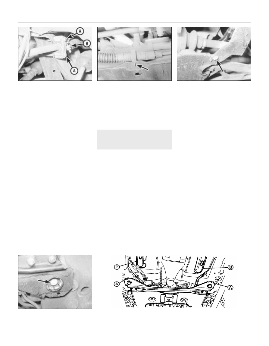
5 Where applicable, release the clip securing the
clutch cable to the subframe (see illustration).
6 Where applicable, remove the screws
and/or clips securing the underbody shields
and wheel arch liners to the subframe (see
illustration).
7 Work around the subframe, and release any
pipes, hoses and wiring from the clips and
brackets on the subframe. Note that it may be
necessary to disconnect certain components
on some models. Make a note of the routing
of all pipes, hoses and wiring to ensure
correct refitting.
8 Support the subframe using a trolley jack
and interposed block of wood. Make sure that
the jack is positioned to adequately support
the subframe without danger of the assembly
falling off the jack.
9 Unscrew the four subframe mounting bolts,
and carefully lower the subframe from under
the vehicle (see illustration). Note that the
subframe rear mounting bolts may be covered
by plastic plugs on certain models.
Refitting
10 From approximately November 1988,
revised subframe rear mounting bolts were
introduced. The later bolts incorporate a
captive washer in place of the Bellville washer
fitted to earlier bolts. If the earlier Bellville
washers are found to be cracked, the later
bolts with captive washers should be fitted. It
is advisable to take the opportunity to fit the
later type of bolts as a matter of course, to
avoid possible problems in the future.
11 From approximately mid-1992, the
subframe rear mountings were modified. The
rear mounting bolts were increased in size
from M12 to M14, and torque wrench setting
was changed accordingly.
12 Subframes with M14 bolts can be
identified from the 6.0 mm holes located
behind the rear mountings (see illustration).
13 Body shells with fixings provided for the
M14 bolts can be identified from the two
10•8 Suspension and steering
8.5 Unscrew the anti-roll bar
clamp bolts (A). There is no need to
remove the metal clamp (B)
9.6 Remove the (arrowed) screws
securing the underbody shields
to the subframe
9.12 Modified front subframe components
9.9 Subframe rear mounting bolt
(arrowed)
9.5 Release the clip (arrowed) securing
the clutch cable to the subframe
A 6.0 mm diameter holes B Body shell stiffeners