Peugeot 405 Haynes (petrol). Manual - part 23
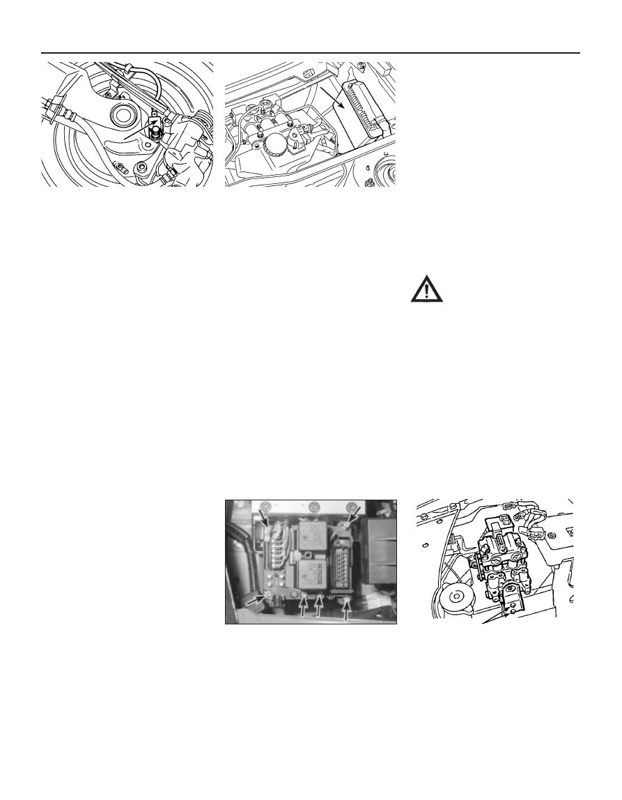
15 Unscrew the securing bolt, and remove
the sensor from the trailing arm (see
illustration).
Refitting
16 Before refitting a sensor, ensure that the
tip is clean. Where applicable, on new sensors
remove the protective sticker from the tip.
17 Lightly grease the sensor location in the
trailing arm, then refit the sensor.
18 Clean the sensor securing bolt, then apply
thread-locking compound to the bolt threads.
Fit the bolt and tighten to the specified torque.
Electronic control unit -
Bendix ABS systems
Removal
19 Disconnect the battery negative lead.
20 The unit is located in the scuttle at the rear
of the engine compartment (see illustration).
21 Open the bonnet, and unclip the cover
from the top of the scuttle to expose the
control unit.
22 Release the securing clip, and disconnect
the wiring plug from the top of the control unit.
23 Unscrew the clamp bolts or nuts, as
applicable, securing the unit to the housing,
then carefully withdraw the unit. Note that on
some models, it may be necessary to
disconnect the control unit wiring harness
earth lead before the unit can be withdrawn.
24 Where applicable, separate the control
unit from the mounting bracket.
Refitting
25 Refitting is a reversal of removal, but
where applicable ensure that the wiring
harness earth lead is securely reconnected.
Electronic control unit -
Bosch ABS system
Removal
26 Disconnect the battery negative lead, then
unclip the control unit cover from the top of
the modulator assembly.
27 Disconnect the three wiring connectors
from the control unit, then slacken and
remove the six Torx retaining screws, and lift
the control unit away from the modulator
assembly (see illustration).
Refitting
28 Refitting is a reversal of the removal
procedure. Ensure that the wiring connectors
are securely reconnected, and do not
overtighten the retaining screws.
Hydraulic control unit
and modulator assembly -
Bendix “integral” ABS
Note: Refer to the Warning in Section 23.
29 No attempt should be made to remove
any of the hydraulic system components on
models equipped with the Bendix “integral”
ABS - refer the operation to a Peugeot dealer.
Modulator assembly -
Bendix “additional” ABS
Removal
30 Disconnect the battery negative lead.
31 Where applicable, unclip the plastic
cover, then disconnect the wiring connectors
from the modulator assembly.
32 Mark the locations of the hydraulic fluid
pipes to ensure correct refitting, then unscrew
the union nuts, and disconnect the pipes from
the modulator assembly. Be prepared for fluid
spillage, and plug the open ends of the pipes
and the modulator, to prevent dirt ingress and
further fluid loss. Note the position of the clip
on the brake pipes to ensure correct refitting.
33 Working under the modulator, unscrew
the two nuts securing the vertical mounting
plate to the main bracket (see illustration).
Withdraw the plate and the mounting rubber
assembly.
34 Unscrew the two nuts securing the
remaining mounting studs to the main
bracket, then manipulate the modulator
assembly from the bracket.
Refitting
35 Refitting is a reversal of removal, bearing
in mind the following.
a) Before refitting, examine the mounting
rubbers, and renew if necessary.
b) Reconnect the fluid pipes to the
assembly, as noted before removal,
ensuring that no dirt enters the system.
Ensure that the brake pipe clip is fitted as
noted before removal.
c) Before reconnecting the wiring
connectors, bleed the complete hydraulic
system as described in Section 2.
Modulator assembly -
Bosch ABS
36 Refer to paragraphs 30 to 35 of this
Section for the Bendix “additional” ABS.
9•20 Braking system
24.15 Rear wheel ABS sensor (arrowed)
24.27 Bosch ABS
electronic control unit
securing screws (arrowed)
24.33 Modulator assembly vertical
mounting bracket-to-main bracket nuts
(arrowed) - Bendix “additional” ABS
24.20 Electronic control unit location
(arrowed) - Bendix “integral” ABS
(left-hand-drive models shown)
Warning: Do not reconnect the
wiring connectors to the
modulator until the hydraulic
circuits have been bled as
described in Section 2.