Peugeot 405 Haynes (petrol). Manual - part 21
much that it is easy to forget the master
cylinder reservoir fluid level; ensure that this is
maintained at least above the “MIN” level line
at all times.
Bleeding -
using a pressure-bleeding kit
22 These kits are usually operated by the
reservoir of pressurised air contained in the
spare tyre. However, note that it will probably
be necessary to reduce the pressure to a
lower level than normal; refer to the
instructions supplied with the kit.
23 By connecting a pressurised, fluid-filled
container to the master cylinder reservoir,
bleeding can be carried out simply by opening
each screw in turn (in the specified sequence),
and allowing the fluid to flow out until no more
air bubbles can be seen in the expelled fluid.
24 This method has the advantage that the
large reservoir of fluid provides an additional
safeguard against air being drawn into the
system during bleeding.
25 Pressure-bleeding is particularly effective
when bleeding “difficult” systems, or when
bleeding the complete system at the time of
routine fluid renewal.
All methods
26 When bleeding is complete, and firm
pedal feel is restored, wash off any spilt fluid,
tighten the bleed screws securely, and refit
their dust caps.
27 Check the hydraulic fluid level in the
master cylinder reservoir, and top-up if
necessary (Chapter 1).
28 Discard any hydraulic fluid that has been
bled from the system; it will not be fit for re-
use.
29 Check the feel of the brake pedal. If it
feels at all spongy, air must still be present in
the system, and further bleeding is required.
Failure to bleed satisfactorily after a
reasonable repetition of the bleeding
procedure may be due to worn master
cylinder seals.
30 On models with ABS, reconnect the wiring
connector to the hydraulic modulator
assembly.
3
Hydraulic pipes and hoses -
renewal
4
Note: Before starting work, refer to the note at
the beginning of Section 2 concerning the
dangers of hydraulic fluid.
1 If any pipe or hose is to be renewed,
minimise fluid loss by first removing the
master cylinder reservoir cap, then tightening
it down onto a piece of polythene to obtain an
airtight seal. Alternatively, flexible hoses can
be sealed, if required, using a proprietary
brake hose clamp; metal brake pipe unions
can be plugged (if care is taken not to allow
dirt into the system) or capped immediately
they are disconnected. Place a wad of rag
under any union that is to be disconnected, to
catch any spilt fluid.
2 If a flexible hose is to be disconnected,
unscrew the brake pipe union nut before
removing the spring clip which secures the
hose to its mounting bracket (see
illustration).
3 To unscrew the union nuts, it is preferable
to obtain a brake pipe spanner of the correct
size; these are available from most large
motor accessory shops. Failing this, a close-
fitting open-ended spanner will be required,
though if the nuts are tight or corroded, their
flats may be rounded-off if the spanner slips.
In such a case, a self-locking wrench is often
the only way to unscrew a stubborn union, but
it follows that the pipe and the damaged nuts
must be renewed on reassembly. Always
clean a union and surrounding area before
disconnecting it. If disconnecting a
component with more than one union, make a
careful note of the connections before
disturbing any of them.
4 If a brake pipe is to be renewed, it can be
obtained, cut to length and with the union
nuts and end flares in place, from Peugeot
dealers. All that is then necessary is to bend it
to shape, following the line of the original,
before fitting it to the car. Alternatively, most
motor accessory shops can make up brake
pipes from kits, but this requires very careful
measurement of the original, to ensure that
the replacement is of the correct length. The
safest answer is usually to take the original to
the shop as a pattern.
5 On refitting, do not overtighten the union
nuts. It is not necessary to exercise brute
force to obtain a sound joint.
6 Ensure that the pipes and hoses are
correctly routed, with no kinks, and that they
are secured in the clips or brackets provided.
After fitting, remove the polythene from the
reservoir, and bleed the hydraulic system as
described in Section 2. Wash off any spilt
fluid, and check carefully for fluid leaks.
4
Front brake pads - renewal
2
1 Apply the handbrake, then jack up the front
of the vehicle and support it on axle stands
(see “Jacking and Vehicle Support”). Remove
the front roadwheels.
2 Trace the brake pad wear sensor wiring
back from the pads, and disconnect it from
the wiring connector (see illustration). Note
the routing of the wiring, and free it from any
relevant retaining clips.
3 Push the piston into its bore by pulling the
caliper outwards.
4 There are two different types of front brake
caliper fitted to the models covered in this
manual as follows.
a) Models with solid front discs -
Bendix calipers.
b) Models with ventilated front discs -
Girling calipers.
9•4 Braking system
4.2 Disconnecting the pad wear sensor
wiring connector
3.2 Flexible hose-to-rigid pipe union at
front wheel arch
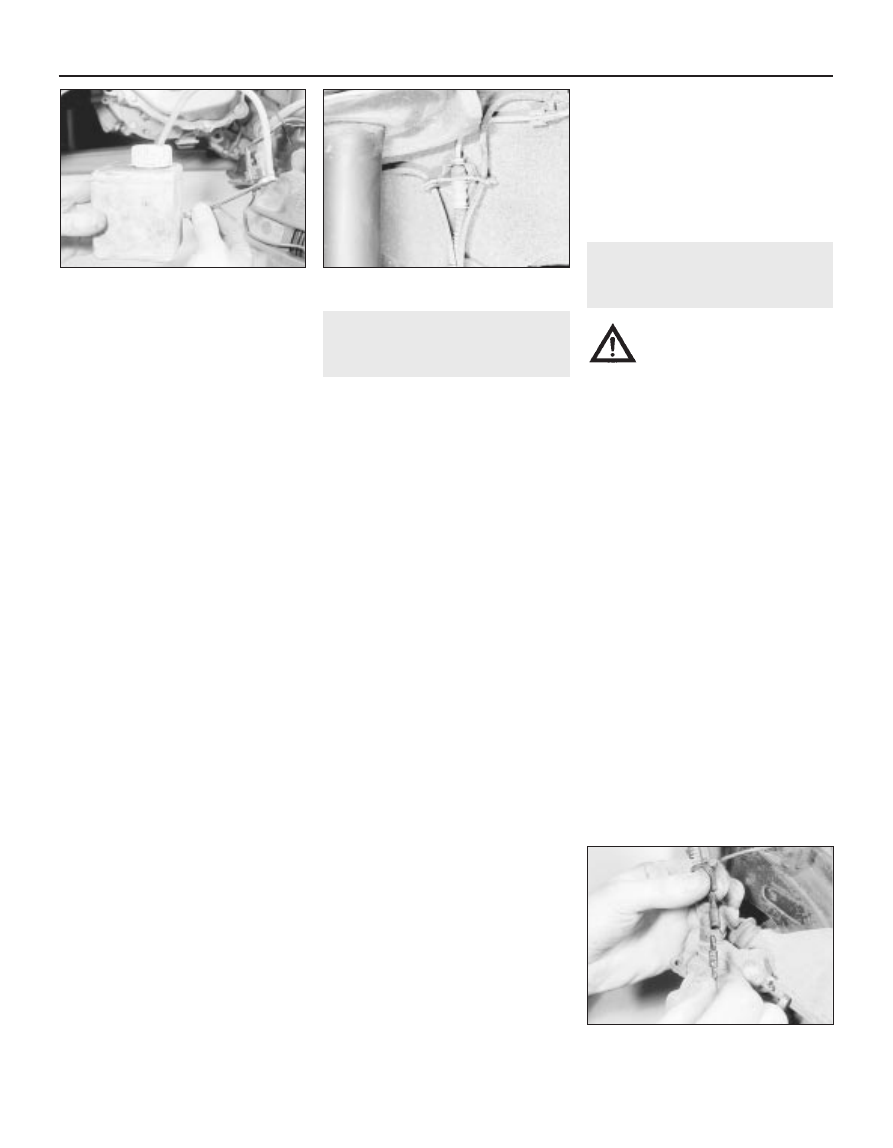
2.20 Using a one-man brake bleeding kit
on a front caliper
Warning: Renew both sets of
front brake pads at the same
time - never renew the pads on
only one wheel, as uneven
braking may result. Note that the dust
created by wear of the pads may contain
asbestos, which is a health hazard. Never
blow it out with compressed air, and don’t
inhale any of it. An approved filtering
mask should be worn when working on
the brakes. DO NOT use petrol or
petroleum-based solvents to clean brake
parts; use brake cleaner or methylated
spirit only.