Peugeot 405 Haynes (petrol). Manual - part 10
holes, and gently “rock” the cylinder head free
towards the front of the car (see Part A). On
wet liner engines, do not try to swivel the head
on the cylinder block/crankcase; it is located
by dowels, as well as by the tops of the liners.
20 When the joint is broken, lift the cylinder
head away. Seek assistance if possible, as it
is a heavy assembly, especially if it is
complete with the manifolds. Remove the
gasket from the top of the block, noting the
two locating dowels. If the locating dowels are
a loose fit, remove them and store them with
the head for safe-keeping. Do not discard the
gasket; it will be needed for identification
purposes.
21 On wet liner engines, do not attempt to
turn the crankshaft with the cylinder head
removed, otherwise the wet liners may be
displaced. Operations that require the
crankshaft to be turned (eg cleaning the
piston crowns), should only be carried out
once the cylinder liners are firmly clamped in
position. In the absence of the special
Peugeot liner clamps, the liners can be
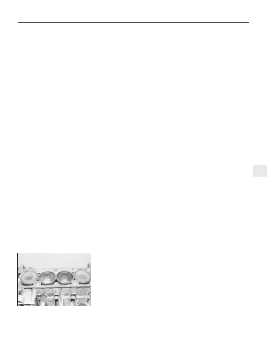
clamped in position as follows. Use large flat
washers positioned underneath suitable-
length bolts, or temporarily refit the original
head bolts, with suitable spacers fitted to their
shanks (see illustration).
22 If the cylinder head is to be dismantled for
overhaul, remove the camshaft as described
in Section 10, then refer to Part C of this
Chapter.
1905 cc 16-valve engines
23 Remove the cylinder head cover as
described in Section 4. Also remove the air
cleaner inlet ducting.
24 Unbolt the plastic cover from over the
power steering pump drive pulley.
25 Disconnect the drivebelt from the power
steering drive pulley with reference to
Chapter 1.
26 Unscrew the bolt and remove the pulley
from the end of the exhaust camshaft.
27 Identify all wiring connections on the
cylinder head then disconnect them. Also
disconnect the coolant hoses from the head.
28 Remove the ignition coil as described in
Chapter 5.
29 Remove the inlet manifold as described in
Chapter 4. To prevent damage to the radiator,
position a piece of cardboard over it. On
models with air conditioning, disconnect the
associated wiring from the inlet manifold.
30 Working as described in Chapter 4,
disconnect the exhaust system front pipe
from the manifold.
31 Place a jack beneath the engine, with a
block of wood on the jack head. Raise the
jack until it is supporting the weight of the
engine.
32 Remove the right-hand engine mounting
bracket with reference to Section 18.
33 Remove the timing belt as described in
Section 7.
34 Working in the reverse of the tightening
sequence, progressively slacken the ten
cylinder head bolts by half a turn at a time,
until all bolts can be unscrewed by hand.
Remove the bolts along with their washers,
noting the correct location of the spacer fitted
to the front left-hand bolt.
35 Release the end of the timing belt cover
from the coolant pump using a screwdriver.
36 With all the cylinder head bolts removed,
the joint between the cylinder head and
gasket and the cylinder block/crankcase must
now be broken without disturbing the wet
liners. Care must be taken to prevent
displacement of the wet liners. Although these
liners are better-located and sealed than
some wet-liner engines, there is still a risk of
coolant and foreign matter leaking into the
sump if the cylinder head is lifted carelessly. If
care is not taken and the liners are moved,
there is also a possibility of the bottom seals
being disturbed, causing leakage after
refitting the head.
37 To break the joint, obtain two L-shaped
metal bars which fit into the cylinder head bolt
holes, and gently “rock” the cylinder head free
towards the front of the car (see Part A). Do
not try to swivel the head on the cylinder
block/crankcase; it is located by dowels, as
well as by the tops of the liners. Take care not
to damage the oil supply tubes when inserting
the metal bars - if necessary remove the tubes
first.
38 When the joint is broken, lift the cylinder
head away. Seek assistance if possible, as it
is a heavy assembly. Remove the gasket from
the top of the block, noting the two locating
dowels. If the locating dowels are a loose fit,
remove them and store them with the head for
safe-keeping. Do not discard the gasket; it will
be needed for identification purposes.
39 Do not attempt to turn the crankshaft with
the cylinder head removed, otherwise the wet
liners may be displaced. Operations that
require the crankshaft to be turned (eg
cleaning the piston crowns), should only be
carried out once the cylinder liners are firmly
clamped in position. In the absence of the
special Peugeot liner clamps, the liners can
be clamped in position as follows. Use large
flat washers positioned underneath suitable-
length bolts, or temporarily refit the original
head bolts, with suitable spacers fitted to their
shanks.
40 If the cylinder head is to be dismantled for
overhaul, remove the camshafts as described
in Section 10, then refer to Part C of this
Chapter.
1998 cc 16-valve engines
41 The procedure is similar to that for the
1905 cc 16-valve engine described above,
except for the following.
a) Where necessary remove both camshafts
at the beginning of the procedure as
described in Section 10.
b) When removing the inlet manifold,
disconnect the ACAV assembly with
reference to Chapter 4.
c) Unbolt the oil dipstick tube from the
cylinder head.
d) The 1998 cc 16-valve engine has dry
liners, and therefore all references to, and
precautions for, wet liners can be ignored.
Preparation for refitting
42 The mating faces of the cylinder head and
cylinder block/crankcase must be perfectly
clean before refitting the head. Use a hard
plastic or wooden scraper to remove all traces
of gasket and carbon; also clean the piston
crowns. On ‘wet’ liner engines, refer to
paragraph 36 before turning the engine. Take
particular care on these models, as the soft
aluminium alloy is easily damaged. On all
models, make sure that the carbon is not
allowed to enter the oil and water passages -
this is particularly important for the lubrication
system, as carbon could block the oil supply
to the engine’s components. Using adhesive
tape and paper, seal the water, oil and bolt
holes in the cylinder block/crankcase. To
prevent carbon entering the gap between the
pistons and bores, smear a little grease in the
gap. After cleaning each piston, use a small
brush to remove all traces of grease and
carbon from the gap, then wipe away the
remainder with a clean rag. Clean all the
pistons in the same way.
43 Check the mating surfaces of the cylinder
block/crankcase and the cylinder head for
nicks, deep scratches and other damage. If
slight, they may be removed carefully with a
file, but if excessive, machining may be the
only alternative to renewal. If warpage of the
cylinder head gasket surface is suspected,
use a straight-edge to check it for distortion.
Refer to Part C of this Chapter if necessary.
44 On ‘wet’ liner engines, check the cylinder
liner protrusion as described in Part C of this
Chapter.
Cylinder head gasket and head bolt
information - 1580 cc, 1761 cc and
1905 cc models
45 On these models (aluminium cylinder
block, wet-liner type engine) when purchasing
a new cylinder head gasket, it is essential that
a gasket of the correct thickness is obtained.
There are two different thicknesses available,
the standard (1.2 mm) gasket which is fitted at
the factory, and a slightly thicker (1.4 mm)
gasket, for use once the head gasket face has
been machined. The two gaskets can be
XU engine in-car repair procedures 2B•19
2B
12.21 Cylinder liners clamped in position
using suitable bolts and large flat washers