Nissan Note E12. Manual - part 628


  Index      Nissan     Nissan Note E12 - Service and Repair Manual


Search            


Content   ..  626  627  628  629   ..


Nissan Note E12. Manual - part 628


TM-70

< SYSTEM DESCRIPTION >

[CVT: RE0F11A]

STRUCTURE AND OPERATION

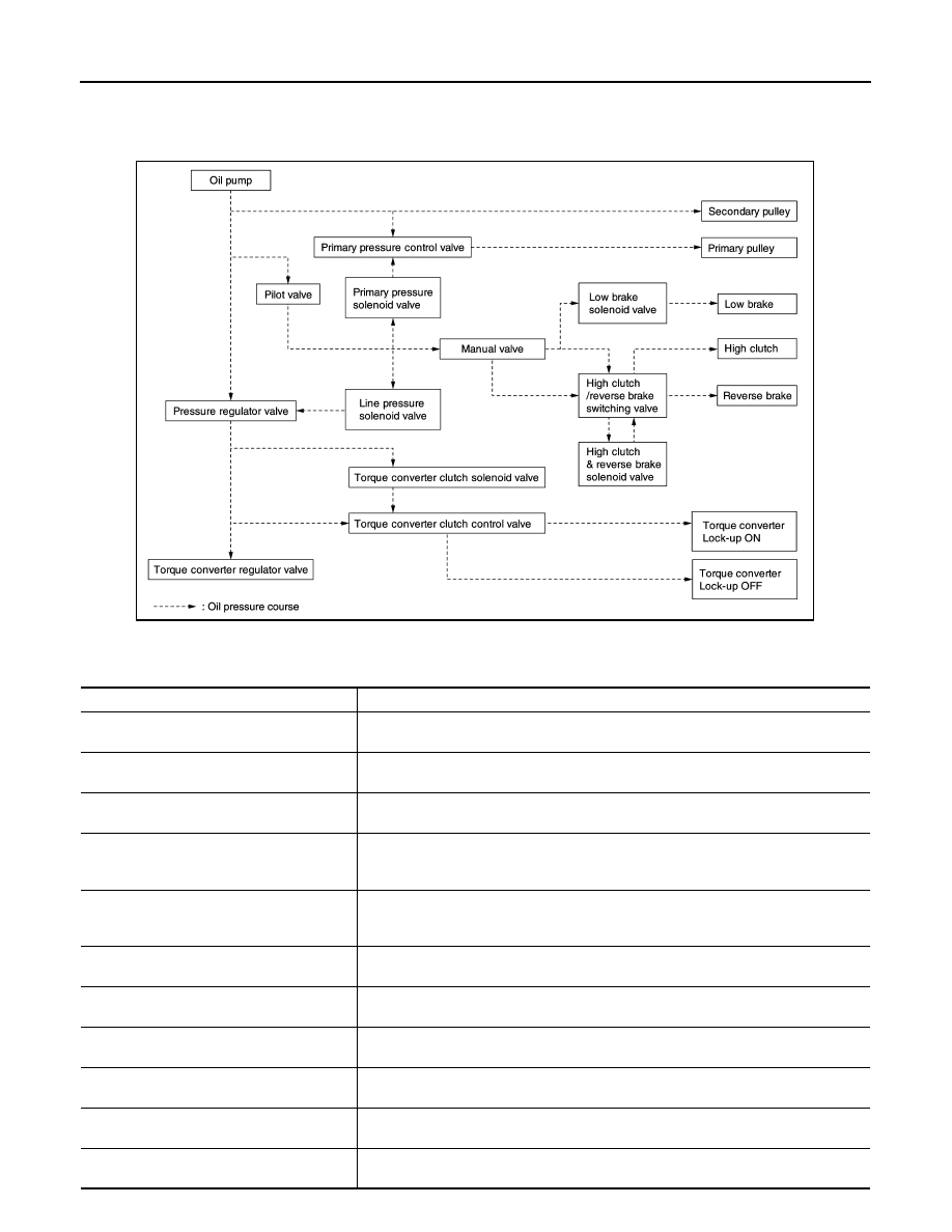
TRANSAXLE : Oil Pressure System 

INFOID:0000000009019856

Oil pressure required for operation of the transaxle transmission mechanism is generated by oil pump, oil

pressure control valve, solenoid valve, etc. 

TRANSAXLE : Component Description

INFOID:0000000009019857

JSDIA1826GB

Part name

Function

Torque converter

It is composed of the cover converter, turbine assembly, stator, pump impeller assem-
bly, etc. It increases the engine torque and transmits the power to the transaxle. 

Oil pump

Through the oil pump drive chain, it uses the vane oil pump driven by the engine. It gen-
erates necessary oil pressure to circulate fluid and to operate the clutch and brake. 

Counter gear set

The power from the torque converter is transmitted to the primary pulley through the 
counter drive gear and the counter driven gear. 

Belt & pulley (Continuously variable transmis-
sion)

It is composed of the primary pulley, secondary pulley, steel belt, etc. and the mecha-
nism performs shifting, changes the gear ratio and transmits the power with oil pressure 
from the control valve. 

Auxiliary gearbox (stepped transmission) 

It is composed of the planetary gear, multi-disc clutch, multi-disc brake, etc. and the 
mechanism performs shifting (1-2 gear shifting and reverse) with oil pressure from the 
control valve. 

Reduction gear set

Conveys power from the transmission mechanism to the reduction gear and the final 
gear. 

Parking mechanism

When the shift lever is changed to P position, the mechanism fixes the parking gear (in-
tegrated with the reduction gear) and the fixes the output shaft. 

Control valve

Controls oil pressure from the oil pump to the pressure suitable for the line pressure 
control system, shift control system, lock-up control system and lubrication system. 

Pressure regulator valve

Adjusts the discharge pressure from the oil pump to the optimum pressure (line pres-
sure) corresponding to the driving condition.

Torque converter regulator valve

Adjusts the feed pressure to the torque converter to the optimum pressure correspond-
ing to the driving condition. 

Pilot valve

Adjusts line pressure and produces a constant pressure (pilot pressure) necessary for 
activating each solenoid valve.

STRUCTURE AND OPERATION

TM-71

< SYSTEM DESCRIPTION >

[CVT: RE0F11A]

C

E

F

G

H

I

J

K

L

M

A

B

TM

N

O

P

FLUID COOLER & FLUID WARMER SYSTEM
FLUID COOLER & FLUID WARMER SYSTEM : System Description

INFOID:0000000009019858

CVT FLUID COOLER SCHEMATIC

CVT fluid cooler air-cooling type

CVT fluid cooler water-cooling type

COMPONENT DESCRIPTION

CVT Oil Warmer

Manual valve

Distributes the clutch and brake operation pressures (pilot pressure) corresponding to 
each shift position. 

High clutch/reverse brake switching valve 

Switches the circuit for the high clutch and the reverse brake. 

Torque converter clutch control valve

It is operated with the torque converter clutch solenoid valve and it adjusts the tighten-
ing pressure and non-tightening pressure of the torque converter clutch piston of the 
torque converter. 

Primary pressure control valve

It is operated with the primary pressure solenoid valve and adjusts the feed pressure to 
the primary pulley. 

Primary pressure solenoid valve

TM-63, "CVT CONTROL SYSTEM : Primary Pressure Solenoid Valve"

Low brake solenoid valve

TM-63, "CVT CONTROL SYSTEM : Low Brake Solenoid Valve"

High clutch & reverse brake solenoid valve

TM-63, "CVT CONTROL SYSTEM : High Clutch & Reverse Brake Solenoid Valve"

Torque converter clutch solenoid valve

TM-63, "CVT CONTROL SYSTEM : Torque Converter Clutch Solenoid Valve"

Line pressure solenoid valve

TM-64, "CVT CONTROL SYSTEM : Line Pressure Solenoid Valve"

Part name

Function

JSDIA4497GB

JSDIA2943GB

TM-72

< SYSTEM DESCRIPTION >

[CVT: RE0F11A]

STRUCTURE AND OPERATION

• The CVT oil warmer (1) is installed on the front part of transaxle

assembly.

• When engine is started while engine and CVT are cold, engine

coolant temperature rises more quickly than CVT fluid tempera-

ture. CVT oil warmer is provided with two circuits for CVT and

engine coolant respectively so that warmed engine coolant warms

CVT quickly. This helps shorten CVT warming up time, improving

fuel economy.

• A cooling effect is obtained when CVT fluid temperature is high.

CVT Fluid Cooler (Water-cooling)

• The CVT fluid cooler (water-cooling) is installed in the radiator side tank (right side).

• CVT fluid is cooled by engine coolant.

CVT Fluid Cooler (Air-cooling)

• The CVT fluid cooler (air-cooling) is installed to vehicle front.

• The CVT fluid cooler (air-cooling) prevents CVT fluid temperature from an abnormal increase while driving

the vehicle. When flowing into the CVT fluid cooler (air-cooling), CVT fluid is cooled by driving blast while

driving the vehicle.

Heater Thermostat

• The heater thermostat (1) is installed on the front part of transaxle

assembly.

• The heater thermostat open and close with set temperature.

SHIFT LOCK SYSTEM
SHIFT LOCK SYSTEM : System Description

INFOID:0000000009019868

The selector lever cannot be shifted from “P” position to any other position unless the ignition switch is in the

ON position and the brake pedal is depressed.

JSDIA2586ZZ

JSDIA2585ZZ

SYSTEM

TM-73

< SYSTEM DESCRIPTION >

[CVT: RE0F11A]

C

E

F

G

H

I

J

K

L

M

A

B

TM

N

O

P

SYSTEM

CVT CONTROL SYSTEM
CVT CONTROL SYSTEM : System Description

INFOID:0000000009019859

SYSTEM DIAGRAM

JSDIA2803GB


Content   ..  626  627  628  629   ..