Nissan Note E12. Manual - part 441


  Index      Nissan     Nissan Note E12 - Service and Repair Manual


Search            


Content   ..  439  440  441  442   ..


Nissan Note E12. Manual - part 441


MA-12

< PERIODIC MAINTENANCE >

RECOMMENDED FLUIDS AND LUBRICANTS

RECOMMENDED FLUIDS AND LUBRICANTS

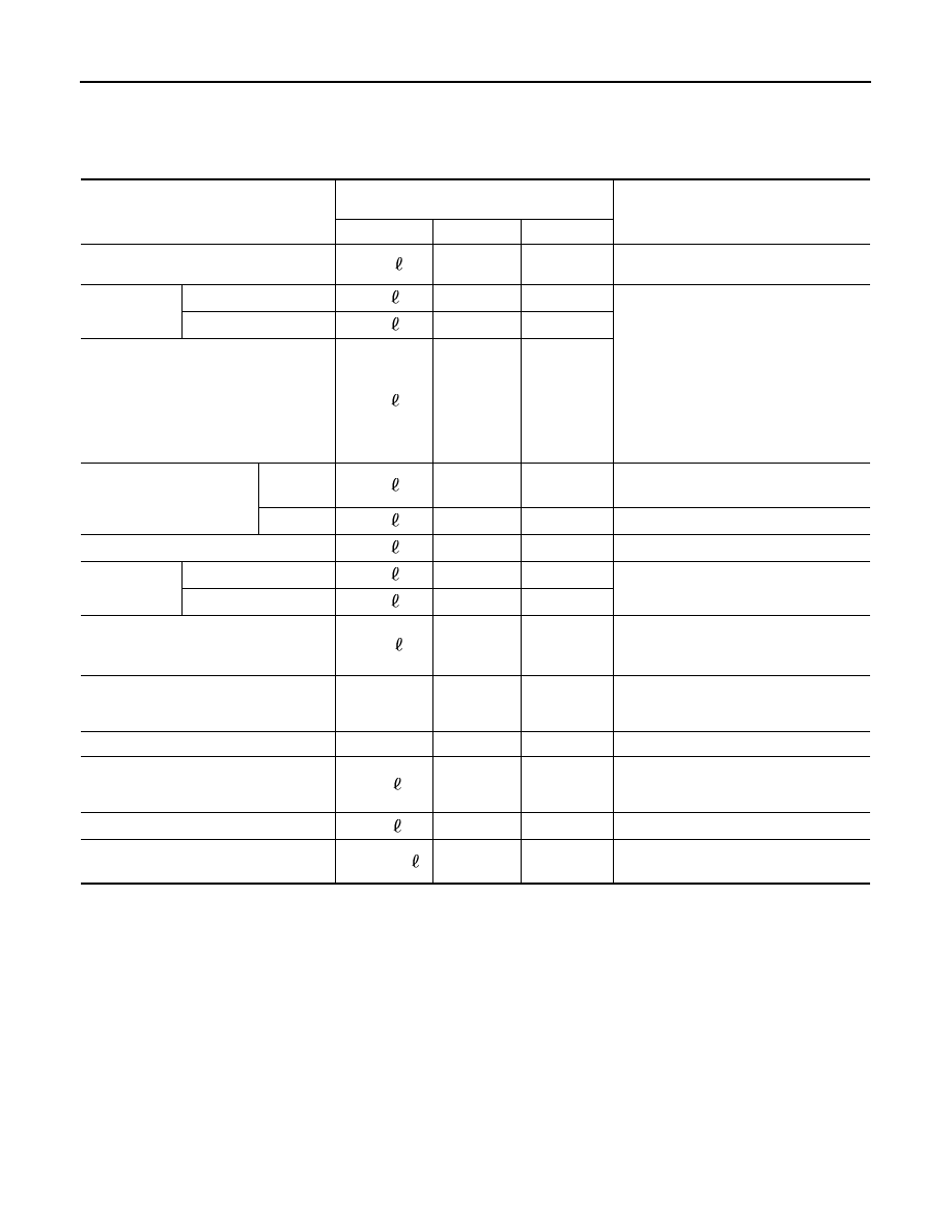
Fluids and Lubricants

INFOID:0000000009452309

*1: For additional information, see “SAE Viscosity Number”.
*2: Use Genuine NISSAN Engine Coolant (blue) or equivalent in its quality, in order to avoid possible aluminum corrosion within the
engine cooling system caused by the use of non-genuine engine coolant.
Note that any repairs for the incidents within the engine cooling system while using non-genuine engine coolant may not be
covered by the warranty even if such incidents occurred during the warranty period.
*3: Use only Genuine NISSAN CVT Fluid NS-3. Using transmission fluid other than Genuine NISSAN CVT Fluid NS-3 will damage the
CVT, which is not covered by the warranty.
*4: If Genuine NISSAN Manual Transmission Fluid (MTF) HQ Multi is not available, API GL-4, Viscosity SAE 75W-85 may be used as a
temporary replacement. However, use Genuine NISSAN Manual Transmission Fluid (MTF) HQ Multi as soon as it is available.
*5: For further information, see “Air conditioning specification label”.

SAE Viscosity Number

INFOID:0000000009452310

GASOLINE ENGINE

• 10W-30 is preferable.

Description

Capacity

(Approximate)

Recommended Fluids/Lubricants

Liter

US measure

Imp measure

Fuel

41.0

10-7/8 gal

9.0 gal

Unleaded regular gasoline with an octane 
rating of at least 87 AKI (RON 91)

Engine oil
Drain and refill

With oil filter change

3.5

3-3/4 qt

3-1/8 qt

For Mexico:
Genuine NISSAN engine oil*

1

API grade SL, SM or SN*

1

ILSAC grade GF-3, GF-4 or GF-5*

1

Viscosity SAE 10W-30*

1

Except for Mexico:
Genuine NISSAN engine oil*

1

API grade SL, SM or SN*

1

ILSAC grade GF-3, GF-4 or GF-5*

1

Without oil filter change

3.2

3-3/8 qt

2-7/8 qt

Dry engine (Overhaul)

3.5

3-3/4 qt

3-1/8 qt

Cooling system (with reser-
voir)

CVT

7.3

7-3/4 qt

6-3/8 qt

Genuine NISSAN Engine Coolant (blue) 
or equivalent in its quality*

2

M/T

6.7

7-1/8 qt

5-7/8 qt

Reservoir tank

0.7

3/4 qt

5/8 qt

CVT fluid

With oil cooler

7.1

7-1/2 qt

6-1/4 qt

Genuine NISSAN CVT Fluid NS-3

*3

Without oil cooler

6.9

7-1/4 qt

6-1/8 qt

Manual transaxle fluid gear oil

2.67

5-5/8 pt

4-3/4 pt

Genuine NISSAN Manual Transmission 
Fluid (MTF) HQ Multi 75W-85 or equiva-
lent*

4

Brake and clutch fluid

Genuine NISSAN Brake Fluid, or equiva-
lent DOT 3
 (US FMVSS No. 116)

Multi-purpose grease

NLGI No. 2 (Lithium soap base)

Windshield washer fluid

2.5 

2-5/8 qt

2-1/4 qt

Genuine NISSAN Windshield Washer 
Concentrate Cleaner & Antifreeze or 
equivalent

Air conditioner system refrigerant

0.4 

0.88 lb

0.88 lb

HFC-134a (R-134a) *5

Air conditioner system oil

110 - 130 

3.9 - 4.6 fl oz

3.9 - 4.6 fl oz

NISSAN A/C System Oil Type DH-PR 
(Type R) or equivalent *

5

RECOMMENDED FLUIDS AND LUBRICANTS

MA-13

< PERIODIC MAINTENANCE >

C

D

E

F

G

H

I

J

K

L

M

B

MA

N

O

A

If 10W-30 is not available, select the viscosity, from the chart, that

is suitable for outside temperature range.

Engine Coolant Mixture Ratio

INFOID:0000000009452311

The engine cooling system is filled at the factory with a high-quality,

year-round and extended life engine coolant. The high quality engine

coolant contains the specific solutions effective for the anti-corrosion

and the anti-freeze function. Therefore, additional cooling system

additives are not necessary.

CAUTION:

• When adding or replacing engine coolant, be sure to use only

a Genuine NISSAN Engine Coolant or equivalent in its quality

with the proper mixture ratio. See the examples shown. 

The use of other types of engine coolant may damage the

engine cooling system. 

• When checking the engine coolant mixture ratio by the coolant

hydrometer, use the chart below to correct your hydrometer reading (specific gravity) according to coolant

temperature.

Mixed coolant specific gravity

Unit: specific gravity

WARNING:

Do not remove the radiator cap when the engine is hot. Serious burns could occur from high-pressure

engine coolant escaping from the radiator. Wrap a thick cloth around the cap. Slowly push down and

turn it a quarter turn to allow built-up pressure to escape. Carefully remove the cap by pushing it down

and turning it all the way.

JPPIA0003GB

SMA089D

Engine coolant mixture 

ratio

Coolant temperature 

°C (°F)

15 (59)

25 (77)

35 (95)

45 (113)

30%

1.046 - 1.050

1.042 - 1.046

1.038 - 1.042

1.033 - 1.038

50%

1.076 - 1.080

1.070 - 1.076

1.065 - 1.071

1.059 - 1.065

MA-14

< PERIODIC MAINTENANCE >

ENGINE MAINTENANCE

ENGINE MAINTENANCE

DRIVE BELT
DRIVE BELT : Exploded View

INFOID:0000000009670478

DRIVE BELT : Removal and Installation

INFOID:0000000009670479

REMOVAL

1. Remove engine undercover. Refer to 

EXT-25, "FRONT UNDER COVER : Removal and Installation"

.

2. Remove wheel and tire (RH) using a power tool. Refer to 

WT-5, "Adjustment"

.

3. Partially remove the fender protector (RH). Refer to 

EXT-24, "Exploded View"

.

4. Loosen the lock nut and then release the belt tension by turning the adjusting bolt.
5. Remove the drive belt.

INSTALLATION

1. Pull the idler pulley in the loosening direction, and then temporarily tighten the lock nut to the following

torque.

NOTE:

Do not move the lock nut from the temporary tightened position. Go to step 2.

2. Install the drive belt on each pulley.

CAUTION:

• Check that there is no engine oil, grease, or engine coolant, etc. in pulley grooves.

• Check that the belt seats securely inside the groove on each pulley.

3. Adjust drive belt tension by turning the adjusting bolt. Refer to 

MA-15, "DRIVE BELT : Adjustment"

.

CAUTION:

• Perform the belt tension adjustment with the lock nut temporarily tightened to the torque specifi-

cation listed in step 1 which prevents the idler pulley from tilting.

• When checking immediately after installation, first adjust it to the specified value. Then, after

turning crankshaft two turns or more, readjust to the specified value to avoid variation in deflec-

tion between pulleys.

1.

Generator

2.

Water pump

3.

Crankshaft pulley

4.

A/C compressor (with A/C models)
Idler pulley (without A/C models)

5.

Tensioner idler pulley

6.

Drive belt

JSBIA1053ZZ

Lock nut
(Temporary tightening)

: 4.4 N·m (0.45 kg-m, 39 in-lb)

ENGINE MAINTENANCE

MA-15

< PERIODIC MAINTENANCE >

C

D

E

F

G

H

I

J

K

L

M

B

MA

N

O

A

4. Tighten the lock nut to final tightening specification.

5. Check that belt tension is within the specification using suitable tool. Refer to 

EM-115, "Drive Belt"

.

DRIVE BELT : Inspection

INFOID:0000000009670480

• Inspection should be done only when engine is cold or over 30

minutes after the engine is stopped.

• Visually check belt for wear, damage, and cracks on inside and

edges.

• Turn crankshaft pulley clockwise twice, and check that the tension on all pulleys equalizes before testing. 
• When measuring deflection, apply 98.1 N (10 kg, 22 lb) at the ( ) marked point.
• Measure the belt tension and frequency using suitable tool at the ( ) marked point.

CAUTION:

• When checking immediately after installation, first adjust it to the specified value. Then, after turning

crankshaft two turns or more, readjust to the specified value to avoid variation in deflection between

pulleys.

DRIVE BELT : Adjustment

INFOID:0000000009670481

CAUTION:

• When belt is replaced with new one, adjust belt tension to the value for “New belt,” because new belt

will not fully seat in the pulley groove.

• When tension of the belt being used exceeds “Limit,” adjust it to the value for “After adjusted.”

• When installing a belt, check it is correctly engaged with the pulley groove.

• Do not allow engine oil or engine coolant to get on the belt.

• Do not twist or bend the belt strongly.
1. Partially remove the fender protector (RH) front side clip. Refer to 

EXT-25, "FRONT UNDER COVER :

Removal and Installation"

.

2. Loosen lock nut (A) and temporarily set to the following torque.

Lock nut (Final tightening)

: 34.8 N·m (3.5 kg-m, 26 ft-lb)

(1)

: Generator

(2)

: Water pump

(3)

: Crankshaft pulley

(4)

: A/C compressor (with A/C models)
  Idler pulley (without A/C models)

(5)

: Idler pulley

(6)

: Drive belt

Belt deflection/belt tension and frequency

: Refer to 

EM-115, "Drive Belt"

.

PBIC3642E

Location

Location of adjuster and tightening method

Drive belt

Adjusting bolt on idler pulley

Lock nut (A)
(Temporary tightening)

: 4.4 N·m (0.45 kg-m, 39 in-lb)

(1)

: Generator

(2)

: Water pump

(3)

: Crankshaft pulley

(4)

: A/C compressor (with A/C models)
  Idler pulley (without A/C models)

(5)

: Idler pulley

PBIC3643E


Content   ..  439  440  441  442   ..